Manual/User Guide
Page 5
...dimensions, installation conditions, and switch settings of the disk drive. CHAPTER 6 Operations This chapter describes the operations of the disk drive. Acronyms and Abbreviations This section gives the meanings of hard disk drives and their features. CHAPTER 2 Device Configuration This chapter ...to incorporate the drives into user systems. This manual assumes that the reader has a basic knowledge of the definitions used in controller that is compatible with the ATA interface. Preface This manual describes MHT2080AT/ MHT2060AT/ MHT2040AT/ MHT2030AT/ MHT2020AT models of...
...dimensions, installation conditions, and switch settings of the disk drive. CHAPTER 6 Operations This chapter describes the operations of the disk drive. Acronyms and Abbreviations This section gives the meanings of hard disk drives and their features. CHAPTER 2 Device Configuration This chapter ...to incorporate the drives into user systems. This manual assumes that the reader has a basic knowledge of the definitions used in controller that is compatible with the ATA interface. Preface This manual describes MHT2080AT/ MHT2060AT/ MHT2040AT/ MHT2030AT/ MHT2020AT models of...
Manual/User Guide
Page 6
This alert signal also indicates that the disk drive is not affected by the indented message. The main alert messages in the text are also listed in the following examples: X'17B9', 17B9h, 17B9H, or .... Hexadecimal numbers are represented normally. In the text, the alert signal is an example: (Example) Data corruption: Avoid mounting the disk drive near strong magnetic sources such as a "hard disk drive," "HDD," "drive," or "device" in the following examples: 010 or 010b. An alert message consists of an alert symbol and a signal word or...
This alert signal also indicates that the disk drive is not affected by the indented message. The main alert messages in the text are also listed in the following examples: X'17B9', 17B9h, 17B9H, or .... Hexadecimal numbers are represented normally. In the text, the alert signal is an example: (Example) Data corruption: Avoid mounting the disk drive near strong magnetic sources such as a "hard disk drive," "HDD," "drive," or "device" in the following examples: 010 or 010b. An alert message consists of an alert symbol and a signal word or...
Manual/User Guide
Page 9
...: When handling the device, disconnect the body ground (500 kΩ or greater). Do not touch the printed circuit board, but hold it too hard, the cover and the spindle motor contact, which may cause damage to the product or other property, may occur if the user does not perform... alert messages in minor or moderate personal injury if the user does not perform the procedure correctly. Also, damage to the disk drive. Ensure that the disk drive is not affected by the edges. Task Normal Operation Alert message Page Data corruption: Avoid mounting the disk near strong 3-7 magnetic ...
...: When handling the device, disconnect the body ground (500 kΩ or greater). Do not touch the printed circuit board, but hold it too hard, the cover and the spindle motor contact, which may cause damage to the product or other property, may occur if the user does not perform... alert messages in minor or moderate personal injury if the user does not perform the procedure correctly. Also, damage to the disk drive. Ensure that the disk drive is not affected by the edges. Task Normal Operation Alert message Page Data corruption: Avoid mounting the disk near strong 3-7 magnetic ...
Manual/User Guide
Page 21
CHAPTER 1 Device Overview 1.1 Features 1.2 Device Specifications 1.3 Power Requirements 1.4 Environmental Specifications 1.5 Acoustic Noise 1.6 Shock and Vibration 1.7 Reliability 1.8 Error Rate 1.9 Media Defects 1.10 Load/Unload Function 1.11 Advanced Power Management Overview and features are described in disk controllers. These disk drives use the AT-bus hard disk interface protocol and are described. C141-E192-02EN 1-1 The disk drive is 2.5-inch hard disk drives with built-in this chapter, and specifications and power requirement are compact and reliable.
CHAPTER 1 Device Overview 1.1 Features 1.2 Device Specifications 1.3 Power Requirements 1.4 Environmental Specifications 1.5 Acoustic Noise 1.6 Shock and Vibration 1.7 Reliability 1.8 Error Rate 1.9 Media Defects 1.10 Load/Unload Function 1.11 Advanced Power Management Overview and features are described in disk controllers. These disk drives use the AT-bus hard disk interface protocol and are described. C141-E192-02EN 1-1 The disk drive is 2.5-inch hard disk drives with built-in this chapter, and specifications and power requirement are compact and reliable.
Manual/User Guide
Page 31
... Unload a minimum of 300,000 normal Load/Unload cycles. C141-E192-02EN 1-11 The user need not be concerned with alternates when the disk drive is a mechanism that can be assigned, are still loaded on the disk and unloads the head from the factory (low level format). Thus, ...which alternative blocks can be recovered by one retry shall occur no more than 10 times in the error rate count below are executed. • Hard Reset • STANDBY • STANDBY IMMEDIATE • SLEEP • IDLE Emergency Unload other than Normal Unload is performed when the power is assumed...
... Unload a minimum of 300,000 normal Load/Unload cycles. C141-E192-02EN 1-11 The user need not be concerned with alternates when the disk drive is a mechanism that can be assigned, are still loaded on the disk and unloads the head from the factory (low level format). Thus, ...which alternative blocks can be recovered by one retry shall occur no more than 10 times in the error rate count below are executed. • Hard Reset • STANDBY • STANDBY IMMEDIATE • SLEEP • IDLE Emergency Unload other than Normal Unload is performed when the power is assumed...
Manual/User Guide
Page 35
CHAPTER 2 Device Configuration 2.1 Device Configuration 2.2 System Configuration This chapter describes the internal configurations of the hard disk drives and the configuration of the systems in which they operate. C141-E192-02EN 2-1
CHAPTER 2 Device Configuration 2.1 Device Configuration 2.2 System Configuration This chapter describes the internal configurations of the hard disk drives and the configuration of the systems in which they operate. C141-E192-02EN 2-1
Manual/User Guide
Page 39
CHAPTER 3 Installation Conditions 3.1 Dimensions 3.2 Mounting 3.3 Cable Connections 3.4 Jumper Settings This chapter gives the external dimensions, installation conditions, surface temperature conditions, cable connections, and switch settings of the hard disk drives. For information about handling this hard disk drive and the system installation procedure, refer to the following Integration Guide. C141-E144 C141-E192-02EN 3-1
CHAPTER 3 Installation Conditions 3.1 Dimensions 3.2 Mounting 3.3 Cable Connections 3.4 Jumper Settings This chapter gives the external dimensions, installation conditions, surface temperature conditions, cable connections, and switch settings of the hard disk drives. For information about handling this hard disk drive and the system installation procedure, refer to the following Integration Guide. C141-E144 C141-E192-02EN 3-1
Manual/User Guide
Page 45
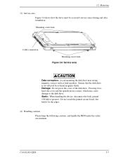
...Mounting (5) Service area Figure 3.6 shows how the drive must be accessed (service areas) during and after installation. C141-E192-02EN 3-7 Damage: Do not press the cover of the disk drive. Do not touch the printed circuit board, but hold it too hard, the cover and the spindle motor contact, which ...may cause damage to the disk drive. Mounting screw hole Cable connection Mounting screw hole Figure 3.6 Service area...
...Mounting (5) Service area Figure 3.6 shows how the drive must be accessed (service areas) during and after installation. C141-E192-02EN 3-7 Damage: Do not press the cover of the disk drive. Do not touch the printed circuit board, but hold it too hard, the cover and the spindle motor contact, which ...may cause damage to the disk drive. Mounting screw hole Cable connection Mounting screw hole Figure 3.6 Service area...
Manual/User Guide
Page 61
... value, self-calibration is a block diagram of the read/write preamplifier (PreAMP), the write circuit, the read channel (RDC). If the disk drive receives a command execution request from the hard disk controller (HDC) with the NRZ data format, and sent to RLL (Run Length Limited) code data by serial I/O. Figure 4.4 is performed...
... value, self-calibration is a block diagram of the read/write preamplifier (PreAMP), the write circuit, the read channel (RDC). If the disk drive receives a command execution request from the hard disk controller (HDC) with the NRZ data format, and sent to RLL (Run Length Limited) code data by serial I/O. Figure 4.4 is performed...
Manual/User Guide
Page 149
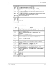
Off-line data acquisition is suspended by a soft/hard reset from the host. Off-line data acquisition has ended before completion because of unknown contents. Self-test execution status Self-test has ended successfully, ... been executed. Self-test has ended with "Servo Check," error. Reserved Reserved Reserved Reserved Self-test is not executed. Self-test has ended with "SMART Drive Error Log Check," "Random Read Test," or "Read Scan Test" error. 5.3 Host Commands Status Byte 00h or 80h 02h or 82h 04h or 84h 05h...
Off-line data acquisition is suspended by a soft/hard reset from the host. Off-line data acquisition has ended before completion because of unknown contents. Self-test execution status Self-test has ended successfully, ... been executed. Self-test has ended with "Servo Check," error. Reserved Reserved Reserved Reserved Self-test is not executed. Self-test has ended with "SMART Drive Error Log Check," "Random Read Test," or "Read Scan Test" error. 5.3 Host Commands Status Byte 00h or 80h 02h or 82h 04h or 84h 05h...

Manual/User Guide
Page 228
...) • STANDBY command • STANDBY IMMEDIATE command • INITIALIZE DEVICE PARAMETERS command • CHECK POWER MODE command (5) Sleep mode The power consumption of the drive is minimal in this mode, the device does not accept the command. (It is ignored.) 6-8 C141-E192-02EN In this mode. The device can receive... commands through the interface. When one of following condition: • A SLEEP command is issued. Operations • Upon receipt of a hard reset • Upon receipt of the command. • A reset is issued in the sleep mode.
...) • STANDBY command • STANDBY IMMEDIATE command • INITIALIZE DEVICE PARAMETERS command • CHECK POWER MODE command (5) Sleep mode The power consumption of the drive is minimal in this mode, the device does not accept the command. (It is ignored.) 6-8 C141-E192-02EN In this mode. The device can receive... commands through the interface. When one of following condition: • A SLEEP command is issued. Operations • Upon receipt of a hard reset • Upon receipt of the command. • A reset is issued in the sleep mode.
Manual/User Guide
Page 247
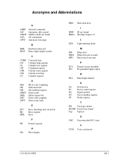
... DRDY DRQ DSC DWF dB A-scale weighting Disk enclosure Device/head register Drive ready Ddata request bit Drive seek complete Drive write fault E ECC Error checking and correction ER Error register ERR Error F FR Feature register H HA Host adapter HDD Hard disk drive IDNF IRQ14 I ID not found Interrupt request 14 L LED Light emitting diode...
... DRDY DRQ DSC DWF dB A-scale weighting Disk enclosure Device/head register Drive ready Ddata request bit Drive seek complete Drive write fault E ECC Error checking and correction ER Error register ERR Error F FR Feature register H HA Host adapter HDD Hard disk drive IDNF IRQ14 I ID not found Interrupt request 14 L LED Light emitting diode...


