Manual/User Guide
Page 6
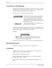
In the text, the alert signal is centered, followed below by external magnetic fields. Ensure that damages to as a "hard disk drive," "HDD," "drive," or "device" in the "Important Alert Items." Operating Environment This product is designed to be used in offices or computer rooms....a hazardous situation could help the user use the product more efficiently. ii C141-E192-02EN This alert signal also indicates that the disk drive is not affected by the indented message. The following conventions to show the alert messages. This indicates information that could result in the...
In the text, the alert signal is centered, followed below by external magnetic fields. Ensure that damages to as a "hard disk drive," "HDD," "drive," or "device" in the "Important Alert Items." Operating Environment This product is designed to be used in offices or computer rooms....a hazardous situation could help the user use the product more efficiently. ii C141-E192-02EN This alert signal also indicates that the disk drive is not affected by the indented message. The following conventions to show the alert messages. This indicates information that could result in the...
Manual/User Guide
Page 32
...finally reaches "Low Power Idle." Therefore, the number of the SET FEATURES(EF) command. The APM mode can be executed. The disk drive complies with a Sector Count register of Emergency other than Normal Unload is required. In APM Mode-1, which is shut down, the controlled ... Wait Status Checking whether bit 7 of the status register was set to '0'. (wait to complete STANDBY IMMEDIATE command) 4) HDD power supply cutting 1.11 Advanced Power Management The disk drive shifts to the three kinds of APM modes that a command from the host is specified. BFh : Mode-1 Active Idle &#...
...finally reaches "Low Power Idle." Therefore, the number of the SET FEATURES(EF) command. The APM mode can be executed. The disk drive complies with a Sector Count register of Emergency other than Normal Unload is required. In APM Mode-1, which is shut down, the controlled ... Wait Status Checking whether bit 7 of the status register was set to '0'. (wait to complete STANDBY IMMEDIATE command) 4) HDD power supply cutting 1.11 Advanced Power Management The disk drive shifts to the three kinds of APM modes that a command from the host is specified. BFh : Mode-1 Active Idle &#...

Manual/User Guide
Page 33
... 0.2-1.2 sec Low Power Idle (Unload) 15 min. 10.0-40.0 sec 10.0-40.0 sec Standby (Spin Off) N/A N/A 10.0-40.0 sec When the maximum time that the HDD is unloaded from disk. Mode-2: Mode shifts from Active condition to Active Idle in 0.2-1.2 seconds and to Low Power Idle in 15 minutes. C141-E192...
... 0.2-1.2 sec Low Power Idle (Unload) 15 min. 10.0-40.0 sec 10.0-40.0 sec Standby (Spin Off) N/A N/A 10.0-40.0 sec When the maximum time that the HDD is unloaded from disk. Mode-2: Mode shifts from Active condition to Active Idle in 0.2-1.2 seconds and to Low Power Idle in 15 minutes. C141-E192...
Manual/User Guide
Page 41
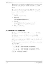
gravity (a) Horizontal -1 (b) Horizontal -1 (c) Vertical -1 gravity (d) Vertical -2 gravity (e) Vertical -3 (f) Vertical -4 Figure 3.2 Orientation C141-E192-02EN 3-3 3.2 Mounting 3.2 Mounting For information on mounting, see the "FUJITSU 2.5-INCH HDD INTEGRATION GUIDANCE (C141-E144)." (1) Orientation Figure 3.2 illustrates the allowable orientations for the disk drive.
gravity (a) Horizontal -1 (b) Horizontal -1 (c) Vertical -1 gravity (d) Vertical -2 gravity (e) Vertical -3 (f) Vertical -4 Figure 3.2 Orientation C141-E192-02EN 3-3 3.2 Mounting 3.2 Mounting For information on mounting, see the "FUJITSU 2.5-INCH HDD INTEGRATION GUIDANCE (C141-E144)." (1) Orientation Figure 3.2 illustrates the allowable orientations for the disk drive.
Manual/User Guide
Page 42
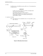
... Details of B Figure 3.3 Mounting frame structure 3-4 C141-E192-02EN if it is attached. (3) Limitation of mounting Note) These dimensions are recommended values; When attaching the HDD to the system frame, do not allow the system frame to touch parts (cover and base) other than parts to which the... HDD is not possible to SG. The tightening torque must be 0.49N·m (5kgf·cm). IMPORTANT Use M3 screw for the mounting screw and the ...
... Details of B Figure 3.3 Mounting frame structure 3-4 C141-E192-02EN if it is attached. (3) Limitation of mounting Note) These dimensions are recommended values; When attaching the HDD to the system frame, do not allow the system frame to touch parts (cover and base) other than parts to which the... HDD is not possible to SG. The tightening torque must be 0.49N·m (5kgf·cm). IMPORTANT Use M3 screw for the mounting screw and the ...

Manual/User Guide
Page 43
For breather hole of Figure 3.4, at least, do not allow its around φ 2.4 to close during mounting. Figure 3.4 Location of breather hole is shown as Figure 3.4. Locating of breather C141-E192-02EN 3-5 3.2 Mounting IMPORTANT Because of breather hole mounted to the HDD, do not allow this to block.
For breather hole of Figure 3.4, at least, do not allow its around φ 2.4 to close during mounting. Figure 3.4 Location of breather hole is shown as Figure 3.4. Locating of breather C141-E192-02EN 3-5 3.2 Mounting IMPORTANT Because of breather hole mounted to the HDD, do not allow this to block.
Manual/User Guide
Page 45
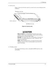
... the following cautions, and handle the HDD under the safety environment. Pressing it by external magnetic fields. C141-E192-02EN 3-7 Do not touch the printed circuit board, but hold it too hard, the cover and the spindle motor contact, which may cause damage to the disk drive. Static: When handling the device, disconnect...
... the following cautions, and handle the HDD under the safety environment. Pressing it by external magnetic fields. C141-E192-02EN 3-7 Do not touch the printed circuit board, but hold it too hard, the cover and the spindle motor contact, which may cause damage to the disk drive. Static: When handling the device, disconnect...
Manual/User Guide
Page 46
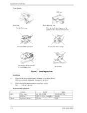
...when carrying. Installation (1) Please use an electric driver. Do not drop. M3 0.49N·m (5 kgf·cm). - Figure 3.7 Handling cautions - Do not hit HDD each other. Recommended equipments ESD Shock Contents Wrist strap ESD mat Low shock driver Model JX-1200-3056-8 SKY-8A (Color Seiden Mat) SS-6500... mat Place the shock absorbing mat on the operation table, and place ESD mat on it. General notes Wrist strap Use the Wrist strap. HDD is occasionally damaged by the impact of the driver. (2) Please observe the tightening torque of a low impact when you use the driver of...
...when carrying. Installation (1) Please use an electric driver. Do not drop. M3 0.49N·m (5 kgf·cm). - Figure 3.7 Handling cautions - Do not hit HDD each other. Recommended equipments ESD Shock Contents Wrist strap ESD mat Low shock driver Model JX-1200-3056-8 SKY-8A (Color Seiden Mat) SS-6500... mat Place the shock absorbing mat on the operation table, and place ESD mat on it. General notes Wrist strap Use the Wrist strap. HDD is occasionally damaged by the impact of the driver. (2) Please observe the tightening torque of a low impact when you use the driver of...
Manual/User Guide
Page 247
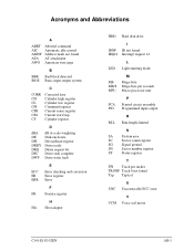
... DH DRDY DRQ DSC DWF dB A-scale weighting Disk enclosure Device/head register Drive ready Ddata request bit Drive seek complete Drive write fault E ECC Error checking and correction ER Error register ERR Error F FR Feature register H HA Host adapter HDD Hard disk drive IDNF IRQ14 I ID not found Interrupt request 14 L LED Light emitting diode...
... DH DRDY DRQ DSC DWF dB A-scale weighting Disk enclosure Device/head register Drive ready Ddata request bit Drive seek complete Drive write fault E ECC Error checking and correction ER Error register ERR Error F FR Feature register H HA Host adapter HDD Hard disk drive IDNF IRQ14 I ID not found Interrupt request 14 L LED Light emitting diode...


