Product Manual
Page 4
... Rev. 24 SCSI Architecture Model-2 (SAM-2) T10/1561D Rev. 14 SCSI Architecture Model-3 (SAM-3) T10/1562D Rev. 05 Serial Attached SCSI (SAS) T10/1601D Rev. 10 Serial Attached SCSI Model-1.1 (SAS 1.1) *1 ANSI = American National Standard Institute In case of conflict between this manual and any packaging part of China This product is...
... Rev. 24 SCSI Architecture Model-2 (SAM-2) T10/1561D Rev. 14 SCSI Architecture Model-3 (SAM-3) T10/1562D Rev. 05 Serial Attached SCSI (SAS) T10/1601D Rev. 10 Serial Attached SCSI Model-1.1 (SAS 1.1) *1 ANSI = American National Standard Institute In case of conflict between this manual and any packaging part of China This product is...
Product Manual
Page 5
...hard disk drives with an embedded Serial Attached SCSI (SAS). Chapter 3 Data Format This chapter describes the data structure, the addressing method, and the defect management. Chapter 5 Installation This chapter explains how to install the disk drives...mounting the disk drive, and confirming drive operation. This chapter also describes diagnostic methods for operation check and the basics of the above disk drive, and gives...collected error information. It includes the notice and procedures for installing the disk drives. C141-E252 1 The need arises, use in details how collect the ...
...hard disk drives with an embedded Serial Attached SCSI (SAS). Chapter 3 Data Format This chapter describes the data structure, the addressing method, and the defect management. Chapter 5 Installation This chapter explains how to install the disk drives...mounting the disk drive, and confirming drive operation. This chapter also describes diagnostic methods for operation check and the basics of the above disk drive, and gives...collected error information. It includes the notice and procedures for installing the disk drives. C141-E252 1 The need arises, use in details how collect the ...
Product Manual
Page 7
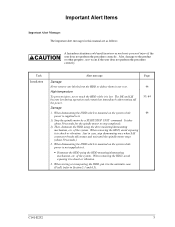
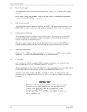
... after turning off contact and wait until the spindle motor stops (about 30 seconds for the spindle motor to stop dismounting once when SAS connector breaks off the power. It takes about 30 seconds.). 2. When dismounting the HDD which is mounted on the system while power...are as follows: A hazardous situation could result in any way. When removing the HDD, avoid exposing it . • Dismount the HDD using the drive mounting/dismounting mechanism, etc. Just in the antistatic case (Fcell) (refer to shock or vibration. 3. Also, damage to shock or vibration. High ...
... after turning off contact and wait until the spindle motor stops (about 30 seconds for the spindle motor to stop dismounting once when SAS connector breaks off the power. It takes about 30 seconds.). 2. When dismounting the HDD which is mounted on the system while power...are as follows: A hazardous situation could result in any way. When removing the HDD, avoid exposing it . • Dismount the HDD using the drive mounting/dismounting mechanism, etc. Just in the antistatic case (Fcell) (refer to shock or vibration. 3. Also, damage to shock or vibration. High ...

Product Manual
Page 9
Diagnostics and Maintenance 7. Command Processing 3. Command Specifications 5. Disk Media Management C141-E252 5 Data Format 4. Data Buffer Management 4. Sense Data and Error Recovery Methods 7. General Description 2. Error Analysis 1. SAS Interface 2. Specifications 3. Installation 6. Parameter Data Format 6. Installation Requirements 5. MANUAL ORGANIZATION PRODUCT MANUAL (This manual) SAS INTERFACE MANUAL 1.
Diagnostics and Maintenance 7. Command Processing 3. Command Specifications 5. Disk Media Management C141-E252 5 Data Format 4. Data Buffer Management 4. Sense Data and Error Recovery Methods 7. General Description 2. Error Analysis 1. SAS Interface 2. Specifications 3. Installation 6. Parameter Data Format 6. Installation Requirements 5. MANUAL ORGANIZATION PRODUCT MANUAL (This manual) SAS INTERFACE MANUAL 1.
Product Manual
Page 15
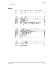
... configuration (Dual port internal cabled environment 18 Example of SAS system configuration (Dual port internal backplane environment 18 Figure 3.1 Figure 3.2 Figure 3.3 Figure 3.4 Figure 3.5 Figure 3.6 Figure 3.7 Figure 3.8 Cylinder configuration 28 Spare ... 4.6 Current waveform (Spin-up 48 Figure 4.7 Current waveform (Max seek 49 Figure 4.8 AC noise filter 50 Figure 4.9 Connector location 50 Figure 4.10 SAS plug connector overview 51 Figure 4.11 Recommended external circuit for Ready LED output 53 Figure 6.1 Figure 6.2 Figure 6.3 Figure 6.4 Test flowchart 72 Unitary packaging ...
... configuration (Dual port internal cabled environment 18 Example of SAS system configuration (Dual port internal backplane environment 18 Figure 3.1 Figure 3.2 Figure 3.3 Figure 3.4 Figure 3.5 Figure 3.6 Figure 3.7 Figure 3.8 Cylinder configuration 28 Spare ... 4.6 Current waveform (Spin-up 48 Figure 4.7 Current waveform (Max seek 49 Figure 4.8 AC noise filter 50 Figure 4.9 Connector location 50 Figure 4.10 SAS plug connector overview 51 Figure 4.11 Recommended external circuit for Ready LED output 53 Figure 6.1 Figure 6.2 Figure 6.3 Figure 6.4 Test flowchart 72 Unitary packaging ...
Product Manual
Page 16
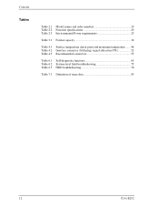
Contents Tables Table 2.1 Model names and order numbers 19 Table 2.2 Function specifications 20 Table 2.3 Environmental/Power requirements 23 Table 3.1 Format capacity 34 Table 4.1 Surface temperature check point and maximum temperature ....... 46 Table 4.2 Interface connector (SAS plug) signal allocation:CN1 52 Table 4.3 Recommended connectors 53 Table 6.1 Self-diagnostic functions 65 Table 6.2 System-level field troubleshooting 75 Table 6.3 HDD troubleshooting 76 Table 7.1 Definition of sense data 83 12 C141-E252
Contents Tables Table 2.1 Model names and order numbers 19 Table 2.2 Function specifications 20 Table 2.3 Environmental/Power requirements 23 Table 3.1 Format capacity 34 Table 4.1 Surface temperature check point and maximum temperature ....... 46 Table 4.2 Interface connector (SAS plug) signal allocation:CN1 52 Table 4.3 Recommended connectors 53 Table 6.1 Self-diagnostic functions 65 Table 6.2 System-level field troubleshooting 75 Table 6.3 HDD troubleshooting 76 Table 7.1 Definition of sense data 83 12 C141-E252
Product Manual
Page 17
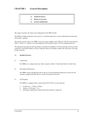
... use of certain Hazardous Substances in electrical and electronic equipment (RoHS) directive issued by European Union (EU). (3) SAS Standard The HDDs are high performance large capacity 3.5-inch hard disk drives with an embedded Serial Attached SCSI (SAS) controller. C141-E252 13 CHAPTER 1 General Description 1.1 Standard Features 1.2 Hardware Structure 1.3 System Configuration This chapter describes the...
... use of certain Hazardous Substances in electrical and electronic equipment (RoHS) directive issued by European Union (EU). (3) SAS Standard The HDDs are high performance large capacity 3.5-inch hard disk drives with an embedded Serial Attached SCSI (SAS) controller. C141-E252 13 CHAPTER 1 General Description 1.1 Standard Features 1.2 Hardware Structure 1.3 System Configuration This chapter describes the...
Product Manual
Page 18
...data blocks on several tracks or cylinder. (7) Multi-segment data buffer The data buffer is 16M bytes. Data are used for the SAS to disk media, thereby enabling high speed write processing. This feature provides the suitable usage environment for completion of write processing to support dual... SAS port connection. The Write Cache feature is supported. The continuous processing up to the disk media before you turn off the HDDs ...
...data blocks on several tracks or cylinder. (7) Multi-segment data buffer The data buffer is 16M bytes. Data are used for the SAS to disk media, thereby enabling high speed write processing. This feature provides the suitable usage environment for completion of write processing to support dual... SAS port connection. The Write Cache feature is supported. The continuous processing up to the disk media before you turn off the HDDs ...

Product Manual
Page 20
... level is very low, and this enables the units to be used in the good space efficiency. (17) Start/Stop of spindle motor Using the SAS primitive or the SCSI command, the host system can be obtained from the errors on each partition (constant density recording). approx. 3.6 Bels at Idle. Also...
... level is very low, and this enables the units to be used in the good space efficiency. (17) Start/Stop of spindle motor Using the SAS primitive or the SCSI command, the host system can be obtained from the errors on each partition (constant density recording). approx. 3.6 Bels at Idle. Also...

Product Manual
Page 21
...The disks have an outer diameter of the actuator arm are controlled and positioned via feedback servo loop. The heads are rotated by a direct-drive hall-less DC motor. The PCBA includes a read channel mounted with a head IC that supports high-speed transmission and an MEEPRML (Modified .../demodulation circuit in order to prevent errors being triggered by a feedback circuit using the counter electromotive current to increase the performance of the SAS controller. Resistive) read element Ramp Load type slider. (3) Spindle motor The disks are positioned on the DE. C141-E252 17 The DE...
...The disks have an outer diameter of the actuator arm are controlled and positioned via feedback servo loop. The heads are rotated by a direct-drive hall-less DC motor. The PCBA includes a read channel mounted with a head IC that supports high-speed transmission and an MEEPRML (Modified .../demodulation circuit in order to prevent errors being triggered by a feedback circuit using the counter electromotive current to increase the performance of the SAS controller. Resistive) read element Ramp Load type slider. (3) Spindle motor The disks are positioned on the DE. C141-E252 17 The DE...

Product Manual
Page 22
... are in the Name Address Authority (NAA) IEEE Registered format defined by the HDDs. 18 C141-E252 Figure 1.1 Example of SAS system configuration (Dual port internal cabled environment) Figure 1.2 Example of 8 bytes as a unique value set for each device. The initiator can... implement an I/O operation on an HDD by using the corresponding SAS address stored by SCSI Primary Command-2 (SPC-2). General Description 1.3 System Configuration For the Serial Attached SCSI, the ANSI standard defines Point-to-Point technology...
... are in the Name Address Authority (NAA) IEEE Registered format defined by the HDDs. 18 C141-E252 Figure 1.1 Example of SAS system configuration (Dual port internal cabled environment) Figure 1.2 Example of 8 bytes as a unique value set for each device. The initiator can... implement an I/O operation on an HDD by using the corresponding SAS address stored by SCSI Primary Command-2 (SPC-2). General Description 1.3 System Configuration For the Serial Attached SCSI, the ANSI standard defines Point-to-Point technology...
Product Manual
Page 23
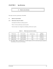
... changed by reinitializing with the user's system. Table 2.1 Model names and order numbers Model name Order number Interface type Capacity (user area) MBA3300RC CA06778-B400 SAS 300 GB (*) MBA3147RC CA06778-B200 SAS 147 GB (*) MBA3073RC CA06778-B100 SAS 73.5 GB (*) (*) One gigabyte (GB) = one billion bytes;
... changed by reinitializing with the user's system. Table 2.1 Model names and order numbers Model name Order number Interface type Capacity (user area) MBA3300RC CA06778-B400 SAS 300 GB (*) MBA3147RC CA06778-B200 SAS 147 GB (*) MBA3073RC CA06778-B100 SAS 73.5 GB (*) (*) One gigabyte (GB) = one billion bytes;
Product Manual
Page 24
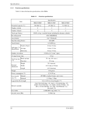
... Power consumption (*5) Data transfer Internal rate (*6) External Logical data block length Related standards Data buffer Acoustic noise (Idle) Specification MBA3300RC MBA3147RC MBA3073RC 300 GB (*2) 147 GB (*2) 73.5 GB (*2) 4 2 1 8 4 2 82604 cyl typ. (standard format including the alternate cylinder) 60/62 MEEPRML 124.7 Gbit/inch2... 30 s typ. 26.1 mm max. 101.6 mm ± 0.25mm 147.0 mm max. 0.8 kg max. 12.36 W typ. 188 MB/s (standard format, most outer) 1.5 Gbps, 3 Gbps 512 to 528 byte (fixed length) (*7) SAS (T10/1562D Rev. 05), SAS1.1 (T10/1601D Rev. 07), SAM...
... Power consumption (*5) Data transfer Internal rate (*6) External Logical data block length Related standards Data buffer Acoustic noise (Idle) Specification MBA3300RC MBA3147RC MBA3073RC 300 GB (*2) 147 GB (*2) 73.5 GB (*2) 4 2 1 8 4 2 82604 cyl typ. (standard format including the alternate cylinder) 60/62 MEEPRML 124.7 Gbit/inch2... 30 s typ. 26.1 mm max. 101.6 mm ± 0.25mm 147.0 mm max. 0.8 kg max. 12.36 W typ. 188 MB/s (standard format, most outer) 1.5 Gbps, 3 Gbps 512 to 528 byte (fixed length) (*7) SAS (T10/1562D Rev. 05), SAS1.1 (T10/1601D Rev. 07), SAM...

Product Manual
Page 33
... (the length of data block and the number of data blocks) can also specify the number of 8 cylinders and outer-most cylinder is also called SA space. The user can be placed in the user space as required to −230).
... (the length of data block and the number of data blocks) can also specify the number of 8 cylinders and outer-most cylinder is also called SA space. The user can be placed in the user space as required to −230).
Product Manual
Page 40
The following are applicable to Subsection 6.3.2 "Auto alternate block allocation processing" of the SAS INTERFACE MANUAL for details. The initiator can access all spare sectors in that cell are recorded in the system space of the HDD as the D ...
The following are applicable to Subsection 6.3.2 "Auto alternate block allocation processing" of the SAS INTERFACE MANUAL for details. The initiator can access all spare sectors in that cell are recorded in the system space of the HDD as the D ...

Product Manual
Page 43
... processing The following processings are performed when the LBA matches the one in the uncorrectable error log: a) Primary media check - This allocation method is allocated.) c) SA and defect map update processing (on the defective data block detected during WRITE command processing as with error. Alternate media check Writes the data that...
... processing The following processings are performed when the LBA matches the one in the uncorrectable error log: a) Primary media check - This allocation method is allocated.) c) SA and defect map update processing (on the defective data block detected during WRITE command processing as with error. Alternate media check Writes the data that...

Product Manual
Page 55
Top view Bottom view Top view Bottom view Figure 4.10 SAS plug connector overview C141-E252 51 Table 4.2 lists the signal allocation of the SAS plug on the HDDs. 4.3 Connection Requirements 4.3.2 Interface connector Figure 4.10 shows the SAS type interface connector (SAS plug) overview.
Top view Bottom view Top view Bottom view Figure 4.10 SAS plug connector overview C141-E252 51 Table 4.2 lists the signal allocation of the SAS plug on the HDDs. 4.3 Connection Requirements 4.3.2 Interface connector Figure 4.10 shows the SAS type interface connector (SAS plug) overview.

Product Manual
Page 56
... (positive) signal S7 GND GND for SAS Primary Port S8 GND GND for +12V P14 +12V +12V power supply input P15 (*1) +12V +12V power supply input P1 to P3 are 3.3V power supply input and pre-charge signals, and not used on MBA3300RC, MBA3147RC, and MBA3073RC. 52 C141-E252 Signal ...Description S1 GND GND for SAS Primary Port S2 RP+ SAS Primary Port Receive (positive) signal S3 RP-
... (positive) signal S7 GND GND for SAS Primary Port S8 GND GND for +12V P14 +12V +12V power supply input P15 (*1) +12V +12V power supply input P1 to P3 are 3.3V power supply input and pre-charge signals, and not used on MBA3300RC, MBA3147RC, and MBA3073RC. 52 C141-E252 Signal ...Description S1 GND GND for SAS Primary Port S2 RP+ SAS Primary Port Receive (positive) signal S3 RP-

Product Manual
Page 61
C141-E252 57 Fix the HDD by using an electric screwdriver, use an SAS address to identify each system. 5.2 Setting 5.2 Setting 5.2.1 Port Address Every device that uses the SAS interface has a unique SAS address, and commands use the screwdriver that does not apply a force on the HDD that would.... The general mounting method and items to be careful not to access the connector after tightening the screws. Every HDD is assigned a unique SAS address before shipment from the factory, so setting of an address is not required before the HDDs are used. 5.3 Mounting HDDs 5.3.1 Mounting ...
C141-E252 57 Fix the HDD by using an electric screwdriver, use an SAS address to identify each system. 5.2 Setting 5.2 Setting 5.2.1 Port Address Every device that uses the SAS interface has a unique SAS address, and commands use the screwdriver that does not apply a force on the HDD that would.... The general mounting method and items to be careful not to access the connector after tightening the screws. Every HDD is assigned a unique SAS address before shipment from the factory, so setting of an address is not required before the HDDs are used. 5.3 Mounting HDDs 5.3.1 Mounting ...

Product Manual
Page 62
...the time of the HDDs.) 58 C141-E252 The following is a general check procedure: a) Confirm that the transfer rate and HDD SAS addresses can respond to commands from the host. (2) Verifying interface connection: When verification of initial operation after power-on is completed normally,... HDDs do not start the LINK RESET sequence defined by sending the NOTIFY (ENABLE SPINUP) primitive to establish synchronization with the connected SAS devices (e.g., the host system). The procedure for verifying operation after the NOTIFY (ENABLE SPINUP) primitive is completed normally, the HDDs can...
...the time of the HDDs.) 58 C141-E252 The following is a general check procedure: a) Confirm that the transfer rate and HDD SAS addresses can respond to commands from the host. (2) Verifying interface connection: When verification of initial operation after power-on is completed normally,... HDDs do not start the LINK RESET sequence defined by sending the NOTIFY (ENABLE SPINUP) primitive to establish synchronization with the connected SAS devices (e.g., the host system). The procedure for verifying operation after the NOTIFY (ENABLE SPINUP) primitive is completed normally, the HDDs can...
