Manual/User Guide
Page 4
Related Standards Product specifications and functions described in this manual takes precedence. ii C141-E185 Document number T10/1236D Rev.20 [NCITS.351:2001] T10/996D Rev.8c [NCITS.306:1998] T10/1157D Rev.20 T10/1365D Rev.7 Title SCSI Primary Commands-2 (SPC-2) SCSI-3 Block Commands (SBC) SCSI Architecture Model-2 (SAM-2) SCSI Parallel Interface-4 (SPI-4) *1 ANSI = American National Standard Institute In case of conflict between this manual and any referenced document, this manual comply with the following ANSI (*1) standards.
Related Standards Product specifications and functions described in this manual takes precedence. ii C141-E185 Document number T10/1236D Rev.20 [NCITS.351:2001] T10/996D Rev.8c [NCITS.306:1998] T10/1157D Rev.20 T10/1365D Rev.7 Title SCSI Primary Commands-2 (SPC-2) SCSI-3 Block Commands (SBC) SCSI Architecture Model-2 (SAM-2) SCSI Parallel Interface-4 (SPI-4) *1 ANSI = American National Standard Institute In case of conflict between this manual and any referenced document, this manual comply with the following ANSI (*1) standards.
Manual/User Guide
Page 5
...drive. This manual is written for installing it into a host computer system. CHAPTER 6 DIAGNOSIS AND MAINTENANCE This chapter describes the automatic diagnosis, and maintenance of the above disk drive..., and gives the requirements and procedures for users who have a basic understanding of fixed disk drives...series disk drives and their...drives. C141-E185 iii PREFACE This manual describes the MAS3735NC/NP, MAS3367NC/NP and MAS3184NC/NP (hereafter, MAS series), 3.5 type fixed disk drives...MAS series disk drives. APPENDIX A TO...drives and discusses their installation environment. CHAPTER ...
...drive. This manual is written for installing it into a host computer system. CHAPTER 6 DIAGNOSIS AND MAINTENANCE This chapter describes the automatic diagnosis, and maintenance of the above disk drive..., and gives the requirements and procedures for users who have a basic understanding of fixed disk drives...series disk drives and their...drives. C141-E185 iii PREFACE This manual describes the MAS3735NC/NP, MAS3367NC/NP and MAS3184NC/NP (hereafter, MAS series), 3.5 type fixed disk drives...MAS series disk drives. APPENDIX A TO...drives and discusses their installation environment. CHAPTER ...
Manual/User Guide
Page 6
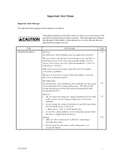
... personal injury may occur if the user does not perform the procedure correctly. CONVENTIONS USED IN THIS MANUAL The MAS3735NC/NP, MAS3367NC/NP and MAS3184NC/NP disk drives are needed. ATTENTION Please forward any comments you may occur if the user does not pay attention or perform ...the procedure correctly. Binary number is represented as "the intelligent disk drive (IDD)", "the drive" or "the device" in the sheet. To make this manual. CONVENTIONS FOR ALERT MESSAGES This manual uses the ...
... personal injury may occur if the user does not perform the procedure correctly. CONVENTIONS USED IN THIS MANUAL The MAS3735NC/NP, MAS3367NC/NP and MAS3184NC/NP disk drives are needed. ATTENTION Please forward any comments you may occur if the user does not pay attention or perform ...the procedure correctly. Binary number is represented as "the intelligent disk drive (IDD)", "the drive" or "the device" in the sheet. To make this manual. CONVENTIONS FOR ALERT MESSAGES This manual uses the ...
Manual/User Guide
Page 7
...the error of terminals not described 5-5 in this manual are applied for their ECC. Hot temperature To prevent injury, do not handle the drive until after the device has 5-1 cooled sufficiently after turning off the power. The user must not change the setting of read sector keeps ...allowable error byte number, correction is shipped from the factory. Do not change the setting of terminals except following setting pins during operation and remain hot immediately...
...the error of terminals not described 5-5 in this manual are applied for their ECC. Hot temperature To prevent injury, do not handle the drive until after the device has 5-1 cooled sufficiently after turning off the power. The user must not change the setting of read sector keeps ...allowable error byte number, correction is shipped from the factory. Do not change the setting of terminals except following setting pins during operation and remain hot immediately...

Manual/User Guide
Page 11
CONTENTS page CHAPTER 1 GENERAL DESCRIPTION 1-1 1.1 Standard Features ...1-2 1.2 Hardware Structure...1-6 1.3 System Configuration ...1-9 CHAPTER 2 SPECIFICATIONS 2-1 2.1 Hardware Specifications...2-1 2.1.1 Model name and order number 2-1 2.1.2 Function specifications...2-2 2.1.3 Environmental specifications 2-4 2.1.4 Error rate ...2-5 2.1.5 Reliability...2-5 2.2 SCSI Function Specifications 2-7 CHAPTER 3 DATA FORMAT 3-1 3.1 Data Space...3-1 3.1.1 Cylinder configuration...3-1 3.1.2 Alternate spare area...3-4 3.1.3 Track format...3-5 3.1.4 Sector format ...3-7 3.1.5 Format ...
CONTENTS page CHAPTER 1 GENERAL DESCRIPTION 1-1 1.1 Standard Features ...1-2 1.2 Hardware Structure...1-6 1.3 System Configuration ...1-9 CHAPTER 2 SPECIFICATIONS 2-1 2.1 Hardware Specifications...2-1 2.1.1 Model name and order number 2-1 2.1.2 Function specifications...2-2 2.1.3 Environmental specifications 2-4 2.1.4 Error rate ...2-5 2.1.5 Reliability...2-5 2.2 SCSI Function Specifications 2-7 CHAPTER 3 DATA FORMAT 3-1 3.1 Data Space...3-1 3.1.1 Cylinder configuration...3-1 3.1.2 Alternate spare area...3-4 3.1.3 Track format...3-5 3.1.4 Sector format ...3-7 3.1.5 Format ...
Manual/User Guide
Page 12
... 5.6.1 Confirming initial operations 5-13 5.6.2 Checking SCSI connection 5-14 5.6.3 Formatting ...5-17 5.6.4 Setting parameters ...5-19 5.7 Dismounting Drives...5-23 5.8 Spare Disk Drive ...5-23 CHAPTER 6 DIAGNOSTICS AND MAINTENANCE 6-1 6.1 Diagnostics ...6-1 6.1.1 Self-diagnostics ...6-1 6.1.2 Test programs...6-4 6.2 Maintenance Information 6-5 6.2.1 Precautions ...6-5 6.2.2 Maintenance requirements 6-6 6.2.3 Maintenance levels ...6-8 6.2.4 Revision numbers ...6-9 6.2.5 Tools and test equipment 6-10 6.2.6 Tests ...6-10 6.3 Operation Check...6-12 6.3.1 Initial seek operation check 6-12...
... 5.6.1 Confirming initial operations 5-13 5.6.2 Checking SCSI connection 5-14 5.6.3 Formatting ...5-17 5.6.4 Setting parameters ...5-19 5.7 Dismounting Drives...5-23 5.8 Spare Disk Drive ...5-23 CHAPTER 6 DIAGNOSTICS AND MAINTENANCE 6-1 6.1 Diagnostics ...6-1 6.1.1 Self-diagnostics ...6-1 6.1.2 Test programs...6-4 6.2 Maintenance Information 6-5 6.2.1 Precautions ...6-5 6.2.2 Maintenance requirements 6-6 6.2.3 Maintenance levels ...6-8 6.2.4 Revision numbers ...6-9 6.2.5 Tools and test equipment 6-10 6.2.6 Tests ...6-10 6.3 Operation Check...6-12 6.3.1 Initial seek operation check 6-12...

Manual/User Guide
Page 15
... only 5-5 CN2 setting terminal (on NP models only 5-6 Checking the SCSI connection (A 5-15 Checking the SCSI connection (B 5-16 Figure 6.1 Figure 6.2 Figure 6.3 Revision label ...6-9 Indicating revision numbers 6-10 Test flowchart...6-11 Figure 7.1 Format of extended sense data 7-2 C141-E185 xiii
... only 5-5 CN2 setting terminal (on NP models only 5-6 Checking the SCSI connection (A 5-15 Checking the SCSI connection (B 5-16 Figure 6.1 Figure 6.2 Figure 6.3 Revision label ...6-9 Indicating revision numbers 6-10 Test flowchart...6-11 Figure 7.1 Format of extended sense data 7-2 C141-E185 xiii
Manual/User Guide
Page 16
TABLES page Table 2.1 Model names and order numbers 2-1 Table 2.2 Function specifications ...2-2 Table 2.3 Environmental/power requirements 2-4 Table 2.4 SCSI function specifications...2-7 Table 3.1 Zone layout and track capacity 3-3 Table 3.4 Format ... only 5-11 Table 6.1 Self-diagnostic functions ...6-1 Table 6.2 System-level field troubleshooting 6-14 Table 6.3 Disk drive troubleshooting ...6-15 Table 7.1 Definition of sense data ...7-3 Table A.1 CN2 setting terminal (on NP model drives only A-2 Table B.1 SCSI connector (SCA2 type LVD 16-bit SCSI): CN1 B-2 Table B.2 SCSI connector ...
TABLES page Table 2.1 Model names and order numbers 2-1 Table 2.2 Function specifications ...2-2 Table 2.3 Environmental/power requirements 2-4 Table 2.4 SCSI function specifications...2-7 Table 3.1 Zone layout and track capacity 3-3 Table 3.4 Format ... only 5-11 Table 6.1 Self-diagnostic functions ...6-1 Table 6.2 System-level field troubleshooting 6-14 Table 6.3 Disk drive troubleshooting ...6-15 Table 7.1 Definition of sense data ...7-3 Table A.1 CN2 setting terminal (on NP model drives only A-2 Table B.1 SCSI connector (SCA2 type LVD 16-bit SCSI): CN1 B-2 Table B.2 SCSI connector ...

Manual/User Guide
Page 18
For the ultra SCSI model, number of system functions. (3) 8-bit SCSI/16-bit SCSI The IDD has 16-bit data bus width (16-bit SCSI), which have the wide transfer function suitable for NP model) • 16-bit SCSI: 16 drives max. (4) High speed data transfer Such a ...Arbitration • Disconnection/Reconnection • Data bus parity The SCSI commands can be useful with NP model. See subsection 5.3.2 for details of the disk drive. 1.1 Standard Features (1) Compactness Since the SCSI controller circuit is embedded in the IDD. • 8-bit SCSI: The data transfer rate on the ...
For the ultra SCSI model, number of system functions. (3) 8-bit SCSI/16-bit SCSI The IDD has 16-bit data bus width (16-bit SCSI), which have the wide transfer function suitable for NP model) • 16-bit SCSI: 16 drives max. (4) High speed data transfer Such a ...Arbitration • Disconnection/Reconnection • Data bus parity The SCSI commands can be useful with NP model. See subsection 5.3.2 for details of the disk drive. 1.1 Standard Features (1) Compactness Since the SCSI controller circuit is embedded in the IDD. • 8-bit SCSI: The data transfer rate on the ...

Manual/User Guide
Page 19
... command is surely terminated with utilizing high data transfer capability of the SCSI bus regardless of actual data transfer rate of the disk drive. (7) Cache feature After executing the READ command, the IDD reads automatically and stores (prefetches) the subsequent data blocks into the ...feature provides the suitable usage environment for completion of write processing to [64K-1] blocks in a command can be limited by specifying block number in a logically continuous data space without concerning the physical structure of the track or cylinder boundaries. To ensure it, you should issue ...
... command is surely terminated with utilizing high data transfer capability of the SCSI bus regardless of actual data transfer rate of the disk drive. (7) Cache feature After executing the READ command, the IDD reads automatically and stores (prefetches) the subsequent data blocks into the ...feature provides the suitable usage environment for completion of write processing to [64K-1] blocks in a command can be limited by specifying block number in a logically continuous data space without concerning the physical structure of the track or cylinder boundaries. To ensure it, you should issue ...

Manual/User Guide
Page 23
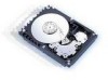
...uses a rotary voice coil motor (VCM), consumes little power and generates little heat. Each model contains following number of 25 mm (0.98 inch) for at the end of the CSS (contact start/stop) type heads are... over the disks when the power is off or the spindle motor is started. MAS3735NC/NP: 4 MAS3367NC/NP: 2 MAS3184NC/NP: 1 (2) Heads The MR (Magnet - Figure 1.3 shows the configuration...heads at least 20,000 contact starts and stops. Resistive) of the actuator arm is controlled by a direct-drive hall-less DC motor. The heads are in the data. (1) Disks The disks have an outer diameter of...
...uses a rotary voice coil motor (VCM), consumes little power and generates little heat. Each model contains following number of 25 mm (0.98 inch) for at the end of the CSS (contact start/stop) type heads are... over the disks when the power is off or the spindle motor is started. MAS3735NC/NP: 4 MAS3367NC/NP: 2 MAS3184NC/NP: 1 (2) Heads The MR (Magnet - Figure 1.3 shows the configuration...heads at least 20,000 contact starts and stops. Resistive) of the actuator arm is controlled by a direct-drive hall-less DC motor. The heads are in the data. (1) Disks The disks have an outer diameter of...

Manual/User Guide
Page 26
... that SCSI ID, then specifies the LUN to select the peripheral device for input/output operation. A unique address (LUN: logical unit number) is a single logical unit, the selectable number of disk drive is assigned for NP model, switch selectable) 16-bit SCSI:Selectable from 0 to 15 (switch selectable) 0 (fixed) 1-10 C141-E185 (1) SCSI...
... that SCSI ID, then specifies the LUN to select the peripheral device for input/output operation. A unique address (LUN: logical unit number) is a single logical unit, the selectable number of disk drive is assigned for NP model, switch selectable) 16-bit SCSI:Selectable from 0 to 15 (switch selectable) 0 (fixed) 1-10 C141-E185 (1) SCSI...
Manual/User Guide
Page 27
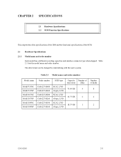
Table 2.1 Model names and order numbers Model name MAS3735NC MAS3735NP MAS3367NC MAS3367NP MAS3184NC MAS3184NP Order number CA06227-B400 CA06227-B460 CA06227-B200 CA06227-B260 CA06227-B100 CA06227-B160 SCSI type SCA2, LVD 68-pin, LVD SCA2, LVD 68-pin, LVD SCA2, LVD 68-pin, LVD Capacity Number of (user area) disks 73.49 GB 4 36...
Table 2.1 Model names and order numbers Model name MAS3735NC MAS3735NP MAS3367NC MAS3367NP MAS3184NC MAS3184NP Order number CA06227-B400 CA06227-B460 CA06227-B200 CA06227-B260 CA06227-B100 CA06227-B160 SCSI type SCA2, LVD 68-pin, LVD SCA2, LVD 68-pin, LVD SCA2, LVD 68-pin, LVD Capacity Number of (user area) disks 73.49 GB 4 36...

Manual/User Guide
Page 28
Ended face Fast 20 SCSI LVD U160 Data transfer rate (*10) Disk drive SCSI Synchronous mode Logical data block length (*11) SCSI command specification Data buffer Acostic noise (Ready) MAS3735NC/NP 73.49 GB 4 8 27,094 11.5 W Specification MAS3367NC/NP 36.77 GB 2 4 27,150 285,696 to 360,960 15,000 ±.../1236D Rev.20), SBC (T10/996D Rev.8c) 8 MB FIFO ring buffer 3.6 Bels typ. (4.1 Bels max.) 2-2 C141-E185 Table 2.2 Function specifications Item Formatted capacity/device (*1) Number of disks Number of heads Number of cylinders (*2) Formatted capacity/track...
Ended face Fast 20 SCSI LVD U160 Data transfer rate (*10) Disk drive SCSI Synchronous mode Logical data block length (*11) SCSI command specification Data buffer Acostic noise (Ready) MAS3735NC/NP 73.49 GB 4 8 27,094 11.5 W Specification MAS3367NC/NP 36.77 GB 2 4 27,150 285,696 to 360,960 15,000 ±.../1236D Rev.20), SBC (T10/996D Rev.8c) 8 MB FIFO ring buffer 3.6 Bels typ. (4.1 Bels max.) 2-2 C141-E185 Table 2.2 Function specifications Item Formatted capacity/device (*1) Number of disks Number of heads Number of cylinders (*2) Formatted capacity/track...

Manual/User Guide
Page 29
The formatted capacity listed in the table is not used. The number of user cylinders and alternate cylinders can be specified at format of the IDD. (*3) The positioning time is as follows: Seek tim [ms] Seek Difference [... speed of initiator and by changing the logical block length and using spare sector space. C141-E185 2-3 See Chapter 3 for 512 bytes per sector. (*2) The number of user cylinders indicates the max., and includes the alternate cylinder.
The formatted capacity listed in the table is not used. The number of user cylinders and alternate cylinders can be specified at format of the IDD. (*3) The positioning time is as follows: Seek tim [ms] Seek Difference [... speed of initiator and by changing the logical block length and using spare sector space. C141-E185 2-3 See Chapter 3 for 512 bytes per sector. (*2) The number of user cylinders indicates the max., and includes the alternate cylinder.

Manual/User Guide
Page 31
... series, Reed Solomon codes are specified at all field sites The number of equipment failures from all field sites C141-E185 2-5 Note: The MTBF is defined as: MTBF= Operating time (hours) at the drive connector side, during initialization and replaced by alternate block assignments are ...not included in each sector where the maximum number of errors (up to 5 byte) can be recovered by one retry should not exceed...
... series, Reed Solomon codes are specified at all field sites The number of equipment failures from all field sites C141-E185 2-5 Note: The MTBF is defined as: MTBF= Operating time (hours) at the drive connector side, during initialization and replaced by alternate block assignments are ...not included in each sector where the maximum number of errors (up to 5 byte) can be recovered by one retry should not exceed...

Manual/User Guide
Page 33
... model) Data bus parity (Data bus CRC) Ο Bus arbitration function Ο Disconnection/reconnection function Ο Addressing SCSI ID 16-bit SCSI LUN (logical unit number) 8-bit SCSI (Single-ended type) Data transfer (Synchronous mode) (LVD type) 16-bit SCSI (Single-ended type) (LVD type) (U160 LVD type) (U320 LVD type...
... model) Data bus parity (Data bus CRC) Ο Bus arbitration function Ο Disconnection/reconnection function Ο Addressing SCSI ID 16-bit SCSI LUN (logical unit number) 8-bit SCSI (Single-ended type) Data transfer (Synchronous mode) (LVD type) 16-bit SCSI (Single-ended type) (LVD type) (U160 LVD type) (U320 LVD type...

Manual/User Guide
Page 37
...space with the MODE SELECT or MODE SELECT EXTENDED command. C141-E185 3-3 The user can be placed in the user space. When the number of cylinders in the user space is a storage area for each series. The default value of logical data blocks is specified, as many... as required to be specified with the MODE SELECT or MODE SELECT EXTENDED command. These also equal the maximum cylinders number for user data. Table 3.1 Zone layout and track capacity Zone Cylinder MAS3735NC/NP MAS3367NC/NP MAS3184NC/NP Byte/track Sector/track 0 0 - 1,848 360,960 705 1 1,849 - 3,697 360...
...space with the MODE SELECT or MODE SELECT EXTENDED command. C141-E185 3-3 The user can be placed in the user space. When the number of cylinders in the user space is a storage area for each series. The default value of logical data blocks is specified, as many... as required to be specified with the MODE SELECT or MODE SELECT EXTENDED command. These also equal the maximum cylinders number for user data. Table 3.1 Zone layout and track capacity Zone Cylinder MAS3735NC/NP MAS3367NC/NP MAS3184NC/NP Byte/track Sector/track 0 0 - 1,848 360,960 705 1 1,849 - 3,697 360...

Manual/User Guide
Page 38
...specified from 0 to 168. The default for diagnostic purposes only and its data block length is always 512KByte. The user cannot change the number of each cell is placed at the end of the cylinders will be used . These spare sectors are located in several different locations for... and an alternate cylinder allocated to each cell in the user space can be used for alternate blocks when primary cylinders in Figure 3.2. The number of each cylinder required in the user space in ascending order. Note: The system space is also called SA space. 3.1.2 Alternate spare area...
...specified from 0 to 168. The default for diagnostic purposes only and its data block length is always 512KByte. The user cannot change the number of each cell is placed at the end of the cylinders will be used . These spare sectors are located in several different locations for... and an alternate cylinder allocated to each cell in the user space can be used for alternate blocks when primary cylinders in Figure 3.2. The number of each cylinder required in the user space in ascending order. Note: The system space is also called SA space. 3.1.2 Alternate spare area...

Manual/User Guide
Page 39
...3.1.3 Track format (1) Physical sector allocation Figure 3.4 shows the allocation of the physical sectors in formats with a byte length. Cell Note: This drive manages alternate spare areas for each zone. Figure 3.2 Spare area in cell An alternate cylinder is used when spare sectors in a cell are used... the logical data block length. The interval of the sector pulse (length of the physical sector) is allocated as alternate cylinders as the number of spare sectors in a cell. 1 cylinder at the end of cylinders. C141-E185 3-5 Therefore, the physical sector length cannot be ...
...3.1.3 Track format (1) Physical sector allocation Figure 3.4 shows the allocation of the physical sectors in formats with a byte length. Cell Note: This drive manages alternate spare areas for each zone. Figure 3.2 Spare area in cell An alternate cylinder is used when spare sectors in a cell are used... the logical data block length. The interval of the sector pulse (length of the physical sector) is allocated as alternate cylinders as the number of spare sectors in a cell. 1 cylinder at the end of cylinders. C141-E185 3-5 Therefore, the physical sector length cannot be ...