Manual/User Guide
Page 11
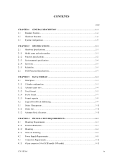
... format...3-5 3.1.4 Sector format ...3-7 3.1.5 Format capacity ...3-9 3.2 Logical Data Block Addressing 3-9 3.3 Defect Management...3-11 3.3.1 Defect list ...3-11 3.3.2 Alternate block allocation 3-11 CHAPTER 4 INSTALLATION REQUIREMENTS 4-1 4.1 Mounting Requirements ...4-1 4.1.1 External dimensions ...4-1 4.1.2 Mounting ...4-4 4.1.3 Notes on mounting ...4-4 4.2 Power Supply Requirements 4-8 4.3 Connection Requirements 4-11 4.3.1 68 pin connector 16-bit SCSI model (NP model 4-11 C141-E166 ix
... format...3-5 3.1.4 Sector format ...3-7 3.1.5 Format capacity ...3-9 3.2 Logical Data Block Addressing 3-9 3.3 Defect Management...3-11 3.3.1 Defect list ...3-11 3.3.2 Alternate block allocation 3-11 CHAPTER 4 INSTALLATION REQUIREMENTS 4-1 4.1 Mounting Requirements ...4-1 4.1.1 External dimensions ...4-1 4.1.2 Mounting ...4-4 4.1.3 Notes on mounting ...4-4 4.2 Power Supply Requirements 4-8 4.3 Connection Requirements 4-11 4.3.1 68 pin connector 16-bit SCSI model (NP model 4-11 C141-E166 ix
Manual/User Guide
Page 15
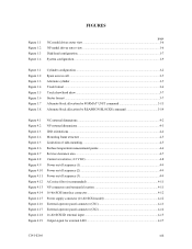
FIGURES Figure 1.1 Figure 1.2 Figure 1.3 Figure 1.4 page NC model drives outer view 1-6 NP model drives outer view 1-6 Disk/head configuration...1-7 System configuration ...1-9 Figure 3.1 Figure 3.2 Figure 3.3 Figure 3.4 Figure 3.5 Figure 3.6 Figure 3.7... 4.11 Figure 4.12 Figure 4.13 Figure 4.14 Figure 4.15 Figure 4.16 Figure 4.17 Figure 4.18 Figure 4.19 NC external dimensions...4-2 NP external dimensions ...4-3 IDD orientations ...4-4 Mounting frame structure ...4-5 Limitation of side-mounting 4-5 Surface temperature measurement points 4-6 Service clearance area ...4-7 Current waveform...
FIGURES Figure 1.1 Figure 1.2 Figure 1.3 Figure 1.4 page NC model drives outer view 1-6 NP model drives outer view 1-6 Disk/head configuration...1-7 System configuration ...1-9 Figure 3.1 Figure 3.2 Figure 3.3 Figure 3.4 Figure 3.5 Figure 3.6 Figure 3.7... 4.11 Figure 4.12 Figure 4.13 Figure 4.14 Figure 4.15 Figure 4.16 Figure 4.17 Figure 4.18 Figure 4.19 NC external dimensions...4-2 NP external dimensions ...4-3 IDD orientations ...4-4 Mounting frame structure ...4-5 Limitation of side-mounting 4-5 Surface temperature measurement points 4-6 Service clearance area ...4-7 Current waveform...
Manual/User Guide
Page 30
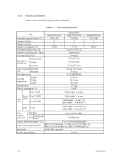
...Read/Write) Track to Track Average Full stroke Start/stop time Start time (*4) Stop time Recording mode External dimensions Height: Width: Depth: Weight (max) Power consumption (*5) Fast 5 SCSI MAP3147NC/NP 147.01 GB 4 8 47,908 Specification MAP3735NC/NP 73.50 GB 2 4 47,978 272,896... 3 m max (*6) Cable length: 1.5 m max (*7) LVD U160 Cable length: 25 m max (*8) Cable length: 12 m max (*9) Data transfer rate (*10) Disk drive SCSI Synchronous mode 64.1 to 528 byte (Fixed length) SCSI command specification SPI-4 (T10/1365D Rev.7), SAM-2 (T10/1157D Rev.20), SPC-2 (T10/1236D Rev...
...Read/Write) Track to Track Average Full stroke Start/stop time Start time (*4) Stop time Recording mode External dimensions Height: Width: Depth: Weight (max) Power consumption (*5) Fast 5 SCSI MAP3147NC/NP 147.01 GB 4 8 47,908 Specification MAP3735NC/NP 73.50 GB 2 4 47,978 272,896... 3 m max (*6) Cable length: 1.5 m max (*7) LVD U160 Cable length: 25 m max (*8) Cable length: 12 m max (*9) Data transfer rate (*10) Disk drive SCSI Synchronous mode 64.1 to 528 byte (Fixed length) SCSI command specification SPI-4 (T10/1365D Rev.7), SAM-2 (T10/1157D Rev.20), SPC-2 (T10/1236D Rev...
Manual/User Guide
Page 53
Note: Dimensions are in mm. C141-E166 4-1 CHAPTER 4 INSTALLATION REQUIREMENTS 4.1 Mounting Requirements 4.2 Power Supply Requirements 4.3 Connection Requirements This chapter describes the environmental, mounting, power supply, and connection requirements. 4.1 Mounting Requirements 4.1.1 External dimensions Figures 4.1 and 4.2 show the external dimensions of the IDD and the locations of the holes for the IDD mounting screws.
Note: Dimensions are in mm. C141-E166 4-1 CHAPTER 4 INSTALLATION REQUIREMENTS 4.1 Mounting Requirements 4.2 Power Supply Requirements 4.3 Connection Requirements This chapter describes the environmental, mounting, power supply, and connection requirements. 4.1 Mounting Requirements 4.1.1 External dimensions Figures 4.1 and 4.2 show the external dimensions of the IDD and the locations of the holes for the IDD mounting screws.

Manual/User Guide
Page 54
Figure 4.1 NC external dimensions 4-2 C141-E166 The value marked with (*) indicates the dimension between mounting holes on the bottom face.
Figure 4.1 NC external dimensions 4-2 C141-E166 The value marked with (*) indicates the dimension between mounting holes on the bottom face.

Manual/User Guide
Page 55
The value marked with (*) indicates the dimension between mounting holes on the bottom face. Figure 4.2 NP external dimensions C141-E166 4-3
The value marked with (*) indicates the dimension between mounting holes on the bottom face. Figure 4.2 NP external dimensions C141-E166 4-3
Manual/User Guide
Page 124
.......7-3 error rate 2-5 error recovery 1-4 error recovery during self-diagnostic 6-3 error recovery parameter 5-19 external dimension 4-1 external magnetic field 4-7 external operator panel circuit example ........4-22 external operator panel connector ....... 4-13, 4-14 F factory ...requirement 4-1 N NC connector location 4-19 NC external dimension 4-2 NC model drive outer view 1-6 note on handling drive 5-1 note on mounting 4-4 NP connector and terminal location 4-11 NP external dimensions 4-3 NP model drive outer view 1-6 O online self-diagnostic 6-3 operation...
.......7-3 error rate 2-5 error recovery 1-4 error recovery during self-diagnostic 6-3 error recovery parameter 5-19 external dimension 4-1 external magnetic field 4-7 external operator panel circuit example ........4-22 external operator panel connector ....... 4-13, 4-14 F factory ...requirement 4-1 N NC connector location 4-19 NC external dimension 4-2 NC model drive outer view 1-6 note on handling drive 5-1 note on mounting 4-4 NP connector and terminal location 4-11 NP external dimensions 4-3 NP model drive outer view 1-6 O online self-diagnostic 6-3 operation...