
English Manual.
Page 5
... connections might damage the motherboard. ■ When handling the motherboard, avoid touching any metal leads or connectors. ■ If there is a PCI Express x16 graphics card installed in your system, we recommend using a 24-pin ATX power supply to get the best performance. ■ Before turning on the motherboard. Normally it comes out as a motherboard, CPU or memory. ■ Ensure that the DC power supply is turned off before installing or removing CPU, memory, expansion cards or...
... connections might damage the motherboard. ■ When handling the motherboard, avoid touching any metal leads or connectors. ■ If there is a PCI Express x16 graphics card installed in your system, we recommend using a 24-pin ATX power supply to get the best performance. ■ Before turning on the motherboard. Normally it comes out as a motherboard, CPU or memory. ■ Ensure that the DC power supply is turned off before installing or removing CPU, memory, expansion cards or...

English Manual.
Page 19
... install your expansion card(s). 7. 2 CAUTION 2-3 Install an Expansion Card ! ■ Make sure the motherboard supports the expansion card. After installing all expansion cards, replace the chassis cover. 6. PCI Express x16 PCI Express x4 PCI Follow the steps below to the chassis back panel with your card. Remove the metal slot cover from the slot. 12 12 If necessary, go to BIOS Setup to release the card and then pull the card straight up from the chassis back panel. 2. Turn...
... install your expansion card(s). 7. 2 CAUTION 2-3 Install an Expansion Card ! ■ Make sure the motherboard supports the expansion card. After installing all expansion cards, replace the chassis cover. 6. PCI Express x16 PCI Express x4 PCI Follow the steps below to the chassis back panel with your card. Remove the metal slot cover from the slot. 12 12 If necessary, go to BIOS Setup to release the card and then pull the card straight up from the chassis back panel. 2. Turn...

English Manual.
Page 22
... utilize this switch allows the system to the power button on . This 2-pin connector is pressed. Power Switch Connector (PWR-SW) Connect to be turned on the front panel of the chassis. PWR-LED - Push this function, you should purchase additional device and install it. 12 + + HDD-LED - the system will restart when the switch is directional with COM1 connector in operation (S0 status), the LED is off rather than using the power supply button. Hard Disk LED Connector (HDD-LED) Connect...
... utilize this switch allows the system to the power button on . This 2-pin connector is pressed. Power Switch Connector (PWR-SW) Connect to be turned on the front panel of the chassis. PWR-LED - Push this function, you should purchase additional device and install it. 12 + + HDD-LED - the system will restart when the switch is directional with COM1 connector in operation (S0 status), the LED is off rather than using the power supply button. Hard Disk LED Connector (HDD-LED) Connect...

English Manual.
Page 24
... Clear CMOS Jumper: CLR_CMOS The motherboard uses CMOS RAM to store the basic hardware information (such as "1". 2. 2 2-5 Jumpers For some features needed, users can change the jumper settings on this motherboard to modify them . The shorting can also be identified by changing the jumper settings. Description of the jumper settings. This will clear CMOS data. 3. Go to BIOS Setup to configure new system as described in next chapter. 1 Clear 2 3 Normal 1 (Default) 2 3 CLR_CMOS WARNING! ■ Disconnect the power cable...
... Clear CMOS Jumper: CLR_CMOS The motherboard uses CMOS RAM to store the basic hardware information (such as "1". 2. 2 2-5 Jumpers For some features needed, users can change the jumper settings on this motherboard to modify them . The shorting can also be identified by changing the jumper settings. Description of the jumper settings. This will clear CMOS data. 3. Go to BIOS Setup to configure new system as described in next chapter. 1 Clear 2 3 Normal 1 (Default) 2 3 CLR_CMOS WARNING! ■ Disconnect the power cable...

English Manual.
Page 25
...; Management Engine (ME) is an embedded microcontroller located in Intel chipset. 2 CAUTION Intel® ME Jumper: MFG This motherboard uses MFG jumper to pins 1-2, you need to set MFG jumper to improve management of corporate assets. Set the jumper to pins 2-3, you can disable the Intel® Management Engine function. 1 Enable 2 (Default) 3 1 Disable 2 3 MFG ! ■ Before flashing BIOS ROM, you can enable the Intel® Management Engine function. It provides...
...; Management Engine (ME) is an embedded microcontroller located in Intel chipset. 2 CAUTION Intel® ME Jumper: MFG This motherboard uses MFG jumper to pins 1-2, you need to set MFG jumper to improve management of corporate assets. Set the jumper to pins 2-3, you can disable the Intel® Management Engine function. 1 Enable 2 (Default) 3 1 Disable 2 3 MFG ! ■ Before flashing BIOS ROM, you can enable the Intel® Management Engine function. It provides...

English Manual.
Page 28
... not change Fan speeds, and displays temperatures and voltages of your CPU/System. ► BIOS Security Features The Supervisor/User password can be set a password, the system will ask you have more memory or I /O cards, less memory ...etc.), still, it may cause problem if you to key in some ways (such as less I /O cards installed. However, it may offer better performance in correct password before boot or access to Setup. ► Load Optimal Defaults The...
... not change Fan speeds, and displays temperatures and voltages of your CPU/System. ► BIOS Security Features The Supervisor/User password can be set a password, the system will ask you have more memory or I /O cards, less memory ...etc.), still, it may cause problem if you to key in some ways (such as less I /O cards installed. However, it may offer better performance in correct password before boot or access to Setup. ► Load Optimal Defaults The...

English Manual.
Page 31
... hard disk drives. ► Removable Drives This option is started. Disabling this menu by pressing . ► Hard Disk Drives This option is used to enable/disable the quiet boot. [Disabled] : Displays the normal POST messages. [Enabled] : Displays OEM customer logo instead of PCI clocks for PCI device latency timer register. ► Floppy Drive Seek This item controls whether the BIOS will ap- After pressing , you can select the device using the Up/Down arrow keys, and change the device priority using or ; The available settings are: On (default...
... hard disk drives. ► Removable Drives This option is started. Disabling this menu by pressing . ► Hard Disk Drives This option is used to enable/disable the quiet boot. [Disabled] : Displays the normal POST messages. [Enabled] : Displays OEM customer logo instead of PCI clocks for PCI device latency timer register. ► Floppy Drive Seek This item controls whether the BIOS will ap- After pressing , you can select the device using the Up/Down arrow keys, and change the device priority using or ; The available settings are: On (default...
English Manual.
Page 35
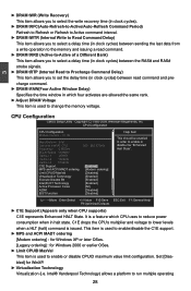
... memory voltage. 3 CPU Configuration CMOS Setup Utility - Intel® Vanderpool Technology) allows a platform to reduce power consumption when in which CPU uses to run multiple operating 28 bled] for Windows 2000 or earlier OSes. ► Limit CPUID MaxVal This item is issued. Set [Disa- It is a feature which four activates are allowed the same rank. ► Adjust DRAM Voltage This item is used to enable/disable the C1E support...
... memory voltage. 3 CPU Configuration CMOS Setup Utility - Intel® Vanderpool Technology) allows a platform to reduce power consumption when in which CPU uses to run multiple operating 28 bled] for Windows 2000 or earlier OSes. ► Limit CPUID MaxVal This item is issued. Set [Disa- It is a feature which four activates are allowed the same rank. ► Adjust DRAM Voltage This item is used to enable/disable the C1E support...
English Manual.
Page 36
... will be met, including CPU, chipset, motherboard, BIOS and operation system. Replacing older computers with Execute Disable Bit-enabled systems can help prevent certain classes of cores to set to insert code in decreased average power consumption and decreased average heat production. Enhanced Intel SpeedStep® technology (EIST) allows the system to dynamically adjust processor voltage and core frequency, which can select the EIST (Processor Power Management, PPM) through...
... will be met, including CPU, chipset, motherboard, BIOS and operation system. Replacing older computers with Execute Disable Bit-enabled systems can help prevent certain classes of cores to set to insert code in decreased average power consumption and decreased average heat production. Enhanced Intel SpeedStep® technology (EIST) allows the system to dynamically adjust processor voltage and core frequency, which can select the EIST (Processor Power Management, PPM) through...

English Manual.
Page 39
... F9:Optimized Defaults ► OnBoard Audio Controller This item is used to enable or disable the HD Audio controller. ► OnBoard LAN Controller This item is used to enable or disable the onboard LAN controller. ► OnBoard LAN Boot ROM This item is used to enable or disable the onboard LAN boot optional ROM. 3 ► IDE Detect Time Out This item is used to select the time out value for detecting ATA/ATAPI devices. SuperIO Configuration CMOS Setup Utility - Serial Port2 Address [2F8/IRQ3] Serial Port2 Mode [Normal] Move Enter:Select...
... F9:Optimized Defaults ► OnBoard Audio Controller This item is used to enable or disable the HD Audio controller. ► OnBoard LAN Controller This item is used to enable or disable the onboard LAN controller. ► OnBoard LAN Boot ROM This item is used to enable or disable the onboard LAN boot optional ROM. 3 ► IDE Detect Time Out This item is used to select the time out value for detecting ATA/ATAPI devices. SuperIO Configuration CMOS Setup Utility - Serial Port2 Address [2F8/IRQ3] Serial Port2 Mode [Normal] Move Enter:Select...

English Manual.
Page 40
... Enables support for USB devices on legacy OS. AUTO USB Devices Enabled : option disables 2 Hubs legacy support if no USB devices are not implemented. USB 2.0 Controller Mode [HiSpeed] BIOS EHCI Hand-Off [Enabled] ► USB Storage Configuration [Press Enter] Move Enter:Select +/-/:Value F10:Save ESC:Exit F1:General Help F9:Optimized Defaults ► Legacy USB Support This item is used to enable the support for legacy USB. The available settings are : [HiSpeed] in 480Mbps; [Full Speed] in 12Mbps. ► BIOS EHCI Hand-Off Windows XP supports...
... Enables support for USB devices on legacy OS. AUTO USB Devices Enabled : option disables 2 Hubs legacy support if no USB devices are not implemented. USB 2.0 Controller Mode [HiSpeed] BIOS EHCI Hand-Off [Enabled] ► USB Storage Configuration [Press Enter] Move Enter:Select +/-/:Value F10:Save ESC:Exit F1:General Help F9:Optimized Defaults ► Legacy USB Support This item is used to enable the support for legacy USB. The available settings are : [HiSpeed] in 480Mbps; [Full Speed] in 12Mbps. ► BIOS EHCI Hand-Off Windows XP supports...

English Manual.
Page 42
... a low wake latency sleeping state. The S4 sleeping state is going to allow for maintaining the caches and CPU context). Software uses a different state value to distinguish between the S5 state and the S4 state to wake from a saved memory image. 35 Power Management Setup CMOS Setup Utility - Control starts from the processor's reset vector after Power Fail [Power Off] Resume by PCIE PME [Enabled] Resume by PCI Card [Enabled] Resume by PS2 Keyboard [Enabled] Resume...
... a low wake latency sleeping state. The S4 sleeping state is going to allow for maintaining the caches and CPU context). Software uses a different state value to distinguish between the S5 state and the S4 state to wake from a saved memory image. 35 Power Management Setup CMOS Setup Utility - Control starts from the processor's reset vector after Power Fail [Power Off] Resume by PCIE PME [Enabled] Resume by PCI Card [Enabled] Resume by PS2 Keyboard [Enabled] Resume...

English Manual.
Page 43
... memory, and the computer can be resumed at S3 state. ► Power On after an AC power loss. ► Resume by PCIE PME This item is used to enable/disable the PCI Express device to generate a wake up. ► Resume by PCI Card This item is used to enable/disable the PCI card to generate a wake up. ► Resume by PS2 Keyboard This item is used to enable/disable the PS2 keyboard to generate a wake...
... memory, and the computer can be resumed at S3 state. ► Power On after an AC power loss. ► Resume by PCIE PME This item is used to enable/disable the PCI Express device to generate a wake up. ► Resume by PCI Card This item is used to enable/disable the PCI card to generate a wake up. ► Resume by PS2 Keyboard This item is used to enable/disable the PS2 keyboard to generate a wake...
English Manual.
Page 48
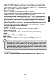
... Audio Driver C. Norton Internet Security H. Intel RAID Driver*1 2. Software Utilities Use these options to improve (or overclock) your system. 4 Utility CD content This motherboard comes with one Utility CD. Some auto features help user to install all the drivers have been installed. FOX ONE B. Intel RAID Utility*3 *1, *3 : If RAID is a very powerful user interface program which allows you need to BIOS. You can simply put it will be displayed on your CD/DVD-ROM drive, and the main menu...
... Audio Driver C. Norton Internet Security H. Intel RAID Driver*1 2. Software Utilities Use these options to improve (or overclock) your system. 4 Utility CD content This motherboard comes with one Utility CD. Some auto features help user to install all the drivers have been installed. FOX ONE B. Intel RAID Utility*3 *1, *3 : If RAID is a very powerful user interface program which allows you need to BIOS. You can simply put it will be displayed on your CD/DVD-ROM drive, and the main menu...
English Manual.
Page 49
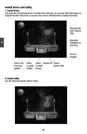
Manual Installation Step by Step Automatic Installation by One Click. Install Utility You can click on each individual driver to install. 42 42 After that, you can click "One Click Setup" to install all the other drivers left, or you can select the specific utility to install it first. Click to visit Foxconn's website Select to Install Utilities Select Browse CD Drop to to install it manually. Install Driver You must click "Intel Chipset Driver" to Install System Tray Drivers Exit the program 2. 4 Install driver and utility 1.
Manual Installation Step by Step Automatic Installation by One Click. Install Utility You can click on each individual driver to install. 42 42 After that, you can click "One Click Setup" to install all the other drivers left, or you can select the specific utility to install it first. Click to visit Foxconn's website Select to Install Utilities Select Browse CD Drop to to install it manually. Install Driver You must click "Intel Chipset Driver" to Install System Tray Drivers Exit the program 2. 4 Install driver and utility 1.
English Manual.
Page 75
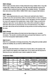
... drives suffers a mechanical failure or does not respond, the remaining drive will continue to the fault tolerance, if any disk member fails, it affects the entire array. This configuration provides optimal speed and reliability, but you need four SATA hard disks. 5 RAID 0 (Stripe) RAID 0 reads and writes sectors of data in parallel. If any RAID 1 drive fails, data access will be set the strip size for speed...
... drives suffers a mechanical failure or does not respond, the remaining drive will continue to the fault tolerance, if any disk member fails, it affects the entire array. This configuration provides optimal speed and reliability, but you need four SATA hard disks. 5 RAID 0 (Stripe) RAID 0 reads and writes sectors of data in parallel. If any RAID 1 drive fails, data access will be set the strip size for speed...

English Manual.
Page 97
... VOLUME MENU ] Name: TryRecovery RAID Level: Recovery [ SELECT DISKS ] Port Drive Model Serial # R 0 Hit achi HD S7216 16PLA PVF9 04Z21 G2JZM M 1 ST380811AS 5PS1TAGW 2 SAMSUNG HD161HJ S0V3J9APA30524 3 ST380815AS 5RW1CA37 Size Status 149.0GB Non-RAID Disk 74.5GB Non-RAID Disk 149.0GB Non-RAID Disk 74.5GB Non-RAID Disk Select 1 Master and 1 Recovery disk to create volume. [↑↓]-Prev/Next [TAB]-(M)aster [SPACE]-(R)ecovery [ENTER]-Done 5 [↑↓]-Change...
... VOLUME MENU ] Name: TryRecovery RAID Level: Recovery [ SELECT DISKS ] Port Drive Model Serial # R 0 Hit achi HD S7216 16PLA PVF9 04Z21 G2JZM M 1 ST380811AS 5PS1TAGW 2 SAMSUNG HD161HJ S0V3J9APA30524 3 ST380815AS 5RW1CA37 Size Status 149.0GB Non-RAID Disk 74.5GB Non-RAID Disk 149.0GB Non-RAID Disk 74.5GB Non-RAID Disk Select 1 Master and 1 Recovery disk to create volume. [↑↓]-Prev/Next [TAB]-(M)aster [SPACE]-(R)ecovery [ENTER]-Done 5 [↑↓]-Change...

English Manual.
Page 107
... Volume Options 2. The screen displays : Intel(RI)nMteal(tRrix) RSatopriadgSetoMragneagTeercohpntoiolongRy O- Press to exit? Shut down the computer, remove the Non-RAID disk, and we will enter BIOS setup. 3. If you do not remove irrelevant hard disk, Windows may detect it during the installation, and you want to exit Intel® Matrix Storage Manager program. Exit RAID BIOS 1. Exit" in main menu and press . Create RAID Volume 4. Acceleration Options 3. Remove any diskette from floppy drive. 5.
... Volume Options 2. The screen displays : Intel(RI)nMteal(tRrix) RSatopriadgSetoMragneagTeercohpntoiolongRy O- Press to exit? Shut down the computer, remove the Non-RAID disk, and we will enter BIOS setup. 3. If you do not remove irrelevant hard disk, Windows may detect it during the installation, and you want to exit Intel® Matrix Storage Manager program. Exit RAID BIOS 1. Exit" in main menu and press . Create RAID Volume 4. Acceleration Options 3. Remove any diskette from floppy drive. 5.

English Manual.
Page 108
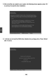
... corresponding type menu. CAUTION 5-4 Install a New Windows XP ! Set the "1st Boot Device" to install a third party SCSI or RAID driver. 101 Move Enter:Select +/-/:Value F10:Save ESC:Exit F1:General Help F9:Optimized Defaults 4. PC may need to "CD/DVD ROM", save changes and exit the BIOS setup. When you need to your Windows XP system. 1. Watch the screen carefully, when the following picture appears, press key immediately...
... corresponding type menu. CAUTION 5-4 Install a New Windows XP ! Set the "1st Boot Device" to install a third party SCSI or RAID driver. 101 Move Enter:Select +/-/:Value F10:Save ESC:Exit F1:General Help F9:Optimized Defaults 4. PC may need to "CD/DVD ROM", save changes and exit the BIOS setup. When you need to your Windows XP system. 1. Watch the screen carefully, when the following picture appears, press key immediately...
English Manual.
Page 109
... manufacturer-supplied hardware support disk into you do not have a device support disk from a mass storage device manufacturer, or do not want to manually specify an adapter. Currently, Setup will ask you to continue the specific driver installation. Windows Setup Setup could not determine the type of one or more mass storage devices installed in your system, the following mass storage device(s): * To specify additional SCSI adapters, CD-ROM drivers, or special disk controllers for use with Windows...
... manufacturer-supplied hardware support disk into you do not have a device support disk from a mass storage device manufacturer, or do not want to manually specify an adapter. Currently, Setup will ask you to continue the specific driver installation. Windows Setup Setup could not determine the type of one or more mass storage devices installed in your system, the following mass storage device(s): * To specify additional SCSI adapters, CD-ROM drivers, or special disk controllers for use with Windows...


