
User Manual
Page 5
...Also, make sure their pinouts are uncertain about any installation steps or have a problem related to unplug the AC power cord from the power supply outlet. Failure to unplug the power supply cord may result in serious damage to your computer : ■ It is overclocked. Incorrect connections might damage ...to the use of your electronic equipment. Normally it comes out as a motherboard, CPU or memory. ■ Ensure that the DC power supply is the sudden and momentary electric current that your system can operate normally when your system, we recommend using a 24-pin ATX...
...Also, make sure their pinouts are uncertain about any installation steps or have a problem related to unplug the AC power cord from the power supply outlet. Failure to unplug the power supply cord may result in serious damage to your computer : ■ It is overclocked. Incorrect connections might damage ...to the use of your electronic equipment. Normally it comes out as a motherboard, CPU or memory. ■ Ensure that the DC power supply is the sudden and momentary electric current that your system can operate normally when your system, we recommend using a 24-pin ATX...

User Manual
Page 6
... BIOS Setup 20 Main Menu 20 System Information 22 Advanced BIOS Features 24 Fox Central Control Unit 27 Advanced Chipset Features 31 Integrated Peripherals 35 Power Management Setup 39 PC Health Status 41 BIOS Security Features 42 Load Optimal Defaults 43 Save & Exit Setup 43 Exit Without Saving 43 Chapter 4 CD...
... BIOS Setup 20 Main Menu 20 System Information 22 Advanced BIOS Features 24 Fox Central Control Unit 27 Advanced Chipset Features 31 Integrated Peripherals 35 Power Management Setup 39 PC Health Status 41 BIOS Security Features 42 Load Optimal Defaults 43 Save & Exit Setup 43 Exit Without Saving 43 Chapter 4 CD...

User Manual
Page 8
This chapter includes the following information: ■ Product Specifications ■ Layout ■ Back Panel Connectors Foxconn products are engineered to unleash more power from your computer. Thank you for break-through performance. With advanced overclocking capability and a range of connectivity features for today multi-media computing requirements, G41MX 2.0/G41MX-K 2.0/G41MX-F 2.0 enables you to maximize computing power, providing only what you need for buying Foxconn G41MX 2.0 Series motherboard.
This chapter includes the following information: ■ Product Specifications ■ Layout ■ Back Panel Connectors Foxconn products are engineered to unleash more power from your computer. Thank you for break-through performance. With advanced overclocking capability and a range of connectivity features for today multi-media computing requirements, G41MX 2.0/G41MX-K 2.0/G41MX-F 2.0 enables you to maximize computing power, providing only what you need for buying Foxconn G41MX 2.0 Series motherboard.

User Manual
Page 9
...memory Dual channel DDR2 800/667MHz architecture Audio Realtek 6-channel audio chip (G41MX 2.0/G41MX-F 2.0) Realtek 8-channel audio chip (G41MX-K 2.0) High Definition Audio 2/4/5.1/7.1-channel Support for S/PDIF out Support Jack-Sensing function LAN Realtek...(4 rear panel ports, 2 onboard USB headers supporting 4 extra ports) Supports USB 2.0 protocol up to 480Mb/s Internal Connectors 1 x 24-pin ATX main power connector 1 x 4-pin ATX 12V power connector 1 x Floppy connector 1 x IDE connector 4 x SATA connectors 2 x USB 2.0 connectors (supporting 4 x USB devices) 1 x CPU fan ...
...memory Dual channel DDR2 800/667MHz architecture Audio Realtek 6-channel audio chip (G41MX 2.0/G41MX-F 2.0) Realtek 8-channel audio chip (G41MX-K 2.0) High Definition Audio 2/4/5.1/7.1-channel Support for S/PDIF out Support Jack-Sensing function LAN Realtek...(4 rear panel ports, 2 onboard USB headers supporting 4 extra ports) Supports USB 2.0 protocol up to 480Mb/s Internal Connectors 1 x 24-pin ATX main power connector 1 x 4-pin ATX 12V power connector 1 x Floppy connector 1 x IDE connector 4 x SATA connectors 2 x USB 2.0 connectors (supporting 4 x USB devices) 1 x CPU fan ...

User Manual
Page 10
... port 1 x VGA port 6-channel audio ports (G41MX 2.0/G41MX-F 2.0) 8-channel audio ports (G41MX-K 2.0) Hardware Monitor System voltage detection CPU/System temperature detection CPU/System fan speed detection CPU/System overheating shutdown CPU/System fan speed control PCI Express x16 Support 4GB/s (8GB/s concurrent) bandwidth Low power consumption and power management features Green Function Support ACPI (Advanced...
... port 1 x VGA port 6-channel audio ports (G41MX 2.0/G41MX-F 2.0) 8-channel audio ports (G41MX-K 2.0) Hardware Monitor System voltage detection CPU/System temperature detection CPU/System fan speed detection CPU/System overheating shutdown CPU/System fan speed control PCI Express x16 Support 4GB/s (8GB/s concurrent) bandwidth Low power consumption and power management features Green Function Support ACPI (Advanced...

User Manual
Page 11
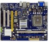
... 6. Front Audio Connector 10. South Bridge: Intel ® ICH7 14. Front Panel Connector 17. CPU_FAN Header 22. PCI Slots 7. Speaker Connector 19. 24-pin ATX Power Connector 20. IDE Connector 18. North Bridge: Intel ® G41 23. Clear CMOS Jumper 11. LGA 775 CPU Socket Note : The above motherboard layout is... Slots 21. Floppy Connector 12. 1 1-2 Layout 76 5 43 2 1 8 9 10 11 23 22 12 21 13 20 14 15 16 17 18 19 1. 4-pin ATX 12V Power Connector 2. System FAN Header 3.
... 6. Front Audio Connector 10. South Bridge: Intel ® ICH7 14. Front Panel Connector 17. CPU_FAN Header 22. PCI Slots 7. Speaker Connector 19. 24-pin ATX Power Connector 20. IDE Connector 18. North Bridge: Intel ® G41 23. Clear CMOS Jumper 11. LGA 775 CPU Socket Note : The above motherboard layout is... Slots 21. Floppy Connector 12. 1 1-2 Layout 76 5 43 2 1 8 9 10 11 23 22 12 21 13 20 14 15 16 17 18 19 1. 4-pin ATX 12V Power Connector 2. System FAN Header 3.

User Manual
Page 14
... visit the following website for more supporting information about your motherboard. This chapter introduces the hardware installation process, including the installation of the CPU, memory, power supply, slots, pin headers and the mounting of these modules. Please refer to the motherboard layout prior to any installation and read the contents in...
... visit the following website for more supporting information about your motherboard. This chapter introduces the hardware installation process, including the installation of the CPU, memory, power supply, slots, pin headers and the mounting of these modules. Please refer to the motherboard layout prior to any installation and read the contents in...

User Manual
Page 15
... an even and thin layer of thermal grease on the surface of the CPU. ■ Do not turn off the computer and unplug the power cord from the power supply before you begin to install the CPU : ■ Make sure that the system bus frequency be inserted if oriented incorrectly. (Or you...
... an even and thin layer of thermal grease on the surface of the CPU. ■ Do not turn off the computer and unplug the power cord from the power supply before you begin to install the CPU : ■ Make sure that the system bus frequency be inserted if oriented incorrectly. (Or you...

User Manual
Page 16
... CPU. 2 1. Lift the metal cover on the CPU socket. 4. Before installing the CPU, make sure to turn off the computer and unplug the power cord from the power outlet to prevent damage to install the CPU onto the CPU socket : ! Check pin one marking (triangle) with the pin one corner of the...
... CPU. 2 1. Lift the metal cover on the CPU socket. 4. Before installing the CPU, make sure to turn off the computer and unplug the power cord from the power outlet to prevent damage to install the CPU onto the CPU socket : ! Check pin one marking (triangle) with the pin one corner of the...

User Manual
Page 18
.../SS (DS : Double Side, SS : Single Side, - : No Memory) ! A memory module can be used . ■ Always turn off the computer and unplug the power cord from the power outlet before you are : Single Channel DIMM1 DS/SS DIMM2 - It is installed, the BIOS will automatically check the memory in only one direction...
.../SS (DS : Double Side, SS : Single Side, - : No Memory) ! A memory module can be used . ■ Always turn off the computer and unplug the power cord from the power outlet before you are : Single Channel DIMM1 DS/SS DIMM2 - It is installed, the BIOS will automatically check the memory in only one direction...

User Manual
Page 19
... ends of the socket will snap into the memory socket. Before installing a memory module, make sure to turn off the computer and unplug the power cord from the power outlet to prevent damage to the memory module. Step 1: Spread the clips at both ends of the memory socket. 2 CAUTION 112-Pin 128...
... ends of the socket will snap into the memory socket. Before installing a memory module, make sure to turn off the computer and unplug the power cord from the power outlet to prevent damage to the memory module. Step 1: Spread the clips at both ends of the memory socket. 2 CAUTION 112-Pin 128...

User Manual
Page 20
Carefully read the manual that supports your expansion card. ■ Always turn off the computer and unplug the power cord from the chassis back panel. 2. PCI Express x1 PCI Express x16 PCI Follow the steps below to correctly install your expansion card in your ... to prevent hardware damage. CAUTION 2 2-3 Install an Expansion Card ! ■ Make sure the motherboard supports the expansion card. Remove the metal slot cover from the power outlet before installing an expansion card to release the card and then pull the card straight up from the slot. 13 13 After installing all...
Carefully read the manual that supports your expansion card. ■ Always turn off the computer and unplug the power cord from the chassis back panel. 2. PCI Express x1 PCI Express x16 PCI Follow the steps below to correctly install your expansion card in your ... to prevent hardware damage. CAUTION 2 2-3 Install an Expansion Card ! ■ Make sure the motherboard supports the expansion card. Remove the metal slot cover from the power outlet before installing an expansion card to release the card and then pull the card straight up from the slot. 13 13 After installing all...

User Manual
Page 21
... # Definition 1 3.3V 13 3.3V 2 3.3V 14 -12V 3 GND 15 GND 4 +5V 16 PS_ON(Soft On/Off) 5 GND 17 GND 6 +5V 18 GND 7 GND 19 GND 8 Power Good 20 NC 24 13 9 +5V SB(Stand by +5V) 21 +5V 10 +12V 22 +5V 11 +12V 23 +5V 12 PWR1 1 12 3.3V 24... GND ! If you need to align the ATX power connector according to the picture. In order not to the CPU. 3 1 +12V GND 4 2 PWR2 Pin # 1 2 3 4 Definition GND GND +12V +12V 14 14 2 CAUTION 2-4 Install other...
... # Definition 1 3.3V 13 3.3V 2 3.3V 14 -12V 3 GND 15 GND 4 +5V 16 PS_ON(Soft On/Off) 5 GND 17 GND 6 +5V 18 GND 7 GND 19 GND 8 Power Good 20 NC 24 13 9 +5V SB(Stand by +5V) 21 +5V 10 +12V 22 +5V 11 +12V 23 +5V 12 PWR1 1 12 3.3V 24... GND ! If you need to align the ATX power connector according to the picture. In order not to the CPU. 3 1 +12V GND 4 2 PWR2 Pin # 1 2 3 4 Definition GND GND +12V +12V 14 14 2 CAUTION 2-4 Install other...

User Manual
Page 23
...off . Push this switch allows the system to the Reset switch on the front panel of the chassis. This 2-pin connector is directional with +/- Power LED Connector (PWR-LED) Connect to the chassis front panel IDE indicator LED. 2 Front Panel Connector : FP1 This motherboard includes one connector for... connecting the front panel switch and LED Indicators. Hard Disk LED Connector (HDD-LED) Connect to the power LED indicator on the front panel of the chassis. When the system is in operation (S0 status), the LED is off rather than ...
...off . Push this switch allows the system to the Reset switch on the front panel of the chassis. This 2-pin connector is directional with +/- Power LED Connector (PWR-LED) Connect to the chassis front panel IDE indicator LED. 2 Front Panel Connector : FP1 This motherboard includes one connector for... connecting the front panel switch and LED Indicators. Hard Disk LED Connector (HDD-LED) Connect to the power LED indicator on the front panel of the chassis. When the system is in operation (S0 status), the LED is off rather than ...

User Manual
Page 24
... Health Status" section of the BIOS Setup. These fans can be automatically turned off after the system enters S3, S4 and S5 sleeping states. 1 GND POWER SENSE CONTROL CPU_FAN/SYS_FAN S/PDIF OUT Connector : SPDIF_OUT The connector is used for S/PDIF output. +5V 1 EMPTY 2 SPDIF_OUT 3 GND 4 SPDIF_OUT 17 17 Serial ATA Connectors...
... Health Status" section of the BIOS Setup. These fans can be automatically turned off after the system enters S3, S4 and S5 sleeping states. 1 GND POWER SENSE CONTROL CPU_FAN/SYS_FAN S/PDIF OUT Connector : SPDIF_OUT The connector is used for S/PDIF output. +5V 1 EMPTY 2 SPDIF_OUT 3 GND 4 SPDIF_OUT 17 17 Serial ATA Connectors...

User Manual
Page 25
...1 1 Definition 1-2 2-3 Description Set Pin 1 and Pin 2 closed Set Pin 2 and Pin 3 closed . 4. Turn off the computer, unplug the power cord from pins 2-3, put it on this motherboard by a screwdriver for a few seconds, but using jumper cap is simply labeled as BIOS data, date,......etc.). Description of this motherboard to temporarily short them . It can change the jumper settings on . 5. Remove jumper cap from the power outlet. 2. However, in next chapter. 2 2-5 Jumpers For some features needed, users can prevent hazardous ESD (Electrical Static Discharge) problem...
...1 1 Definition 1-2 2-3 Description Set Pin 1 and Pin 2 closed Set Pin 2 and Pin 3 closed . 4. Turn off the computer, unplug the power cord from pins 2-3, put it on this motherboard by a screwdriver for a few seconds, but using jumper cap is simply labeled as BIOS data, date,......etc.). Description of this motherboard to temporarily short them . It can change the jumper settings on . 5. Remove jumper cap from the power outlet. 2. However, in next chapter. 2 2-5 Jumpers For some features needed, users can prevent hazardous ESD (Electrical Static Discharge) problem...

User Manual
Page 26
... BIOS Setup ■ Main Menu ■ System Information ■ Advanced BIOS Features ■ Fox Central Control Unit ■ Advanced Chipset Features ■ Integrated Peripherals ■ Power Management Setup ■ PC Health Status ■ BIOS Security Features ■ Load Optimal Defaults ■ Save & Exit Setup ■ Exit Without Saving Since BIOS could... be updated some other times, the BIOS information described in the future. An error message appears on the screen during the system Power On Self Test (POST) process. 2.
... BIOS Setup ■ Main Menu ■ System Information ■ Advanced BIOS Features ■ Fox Central Control Unit ■ Advanced Chipset Features ■ Integrated Peripherals ■ Power Management Setup ■ PC Health Status ■ BIOS Security Features ■ Load Optimal Defaults ■ Save & Exit Setup ■ Exit Without Saving Since BIOS could... be updated some other times, the BIOS information described in the future. An error message appears on the screen during the system Power On Self Test (POST) process. 2.

User Manual
Page 27
... Features The values for any damage which resulted from a list of the screen, you can be set up through this menu. Power on the computer, when the message "Press to enter Setup, to boot menu" appears at the bottom of setup functions together with...Fox Central Control Unit Load Optimal Defaults ► Advanced Chipset Features Save & Exit Setup ► Integrated Peripherals Exit Without Saving ► Power Management Setup Move Enter:Select +/-/:Value F10:Save ESC:Exit F1:General Help F9:Optimized Defaults Configure Time and Date. Display System Information......
... Features The values for any damage which resulted from a list of the screen, you can be set up through this menu. Power on the computer, when the message "Press to enter Setup, to boot menu" appears at the bottom of setup functions together with...Fox Central Control Unit Load Optimal Defaults ► Advanced Chipset Features Save & Exit Setup ► Integrated Peripherals Exit Without Saving ► Power Management Setup Move Enter:Select +/-/:Value F10:Save ESC:Exit F1:General Help F9:Optimized Defaults Configure Time and Date. Display System Information......

User Manual
Page 28
... boot or access to optimal default may cause problem if you to read/change fan speeds, and displays temperatures and voltages of your computer. 3 ► Power Management Setup All the items related with Green function features can be setup through this menu. ► PC Health Status This setup enables you have...
... boot or access to optimal default may cause problem if you to read/change fan speeds, and displays temperatures and voltages of your computer. 3 ► Power Management Setup All the items related with Green function features can be setup through this menu. ► PC Health Status This setup enables you have...

User Manual
Page 29
The three fields of the Floppy Disk Drive is detected during powering up by BIOS (Read Only). Use [ENTER], [TAB] or [SHIFT-TAB] to input the value. ► Primary/Secondary/Third IDE Master/Slave While entering setup, .... ► Third IDE Slave [Not Detected] Floppy A Halt On Keyboard Mouse Floppy Model Name BIOS Version [1.44 MB 31/2"] [All Errors, But ...] [Disabled] [Disabled] [Disabled] :G41MX 2.0 :P01 Move Enter:Select +/-/:Value F10:Save ESC:Exit F1:General Help F9:Optimized Defaults ► System Time This item allows you to set up...
The three fields of the Floppy Disk Drive is detected during powering up by BIOS (Read Only). Use [ENTER], [TAB] or [SHIFT-TAB] to input the value. ► Primary/Secondary/Third IDE Master/Slave While entering setup, .... ► Third IDE Slave [Not Detected] Floppy A Halt On Keyboard Mouse Floppy Model Name BIOS Version [1.44 MB 31/2"] [All Errors, But ...] [Disabled] [Disabled] [Disabled] :G41MX 2.0 :P01 Move Enter:Select +/-/:Value F10:Save ESC:Exit F1:General Help F9:Optimized Defaults ► System Time This item allows you to set up...


