
English Manual.
Page 6
... Internal Connectors 14 Jumpers 18 Chapter 3 BIOS Setup Enter BIOS Setup 20 Main Menu 20 System Information 22 Fox Central Control Unit 24 Advanced BIOS Features 29 Advanced Chipset Features 31 Integrated Peripherals 33 Green System Mode 38 BIOS Security Features 43 Load Optimized Defaults 44 Save & Exit Setup 44 Exit Without Saving 44 Chapter 4 CD Instruction Utility CD content 46 Install driver and utility 47 FOX ONE Main Page 49 CPU Control 54 Frequency Control 56 Limit Setting...
... Internal Connectors 14 Jumpers 18 Chapter 3 BIOS Setup Enter BIOS Setup 20 Main Menu 20 System Information 22 Fox Central Control Unit 24 Advanced BIOS Features 29 Advanced Chipset Features 31 Integrated Peripherals 33 Green System Mode 38 BIOS Security Features 43 Load Optimized Defaults 44 Save & Exit Setup 44 Exit Without Saving 44 Chapter 4 CD Instruction Utility CD content 46 Install driver and utility 47 FOX ONE Main Page 49 CPU Control 54 Frequency Control 56 Limit Setting...
English Manual.
Page 10
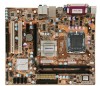
1 Back Panel 1 x PS/2 keyboard port Connectors 1 x PS/2 mouse port 1 x Serial Port 1 x Parallel Port 4 x USB 2.0 ports 1 x RJ-45 LAN port 1 x VGA port 8-channel Audio ports Hardware Monitor System voltage detection CPU/System temperature detection CPU/System fan speed detection CPU/System overheating warning CPU/System fan speed control PCI Express x1 Support 250MB/s (500MB/s concurrent) bandwidth Low power consumption and power management features PCI Express x16 Support 4GB/s (8GB/s concurrent) bandwidth Low power consumption and power management...
1 Back Panel 1 x PS/2 keyboard port Connectors 1 x PS/2 mouse port 1 x Serial Port 1 x Parallel Port 4 x USB 2.0 ports 1 x RJ-45 LAN port 1 x VGA port 8-channel Audio ports Hardware Monitor System voltage detection CPU/System temperature detection CPU/System fan speed detection CPU/System overheating warning CPU/System fan speed control PCI Express x1 Support 250MB/s (500MB/s concurrent) bandwidth Low power consumption and power management features PCI Express x16 Support 4GB/s (8GB/s concurrent) bandwidth Low power consumption and power management...

English Manual.
Page 20
... graphics card is fully seated in the slot. 3. Turn on the card are completely inserted into the PCI Express x16 slot. PCI Express x16 PCI Express x1 PCI Follow the steps below to prevent hardware damage. CAUTION 2 2-3 Install an Expansion Card ! ■ Make sure the motherboard supports the expansion card. Carefully read the manual that supports your expansion card. ■ Always turn off the computer and unplug the power cord from the chassis back panel...
... graphics card is fully seated in the slot. 3. Turn on the card are completely inserted into the PCI Express x16 slot. PCI Express x16 PCI Express x1 PCI Follow the steps below to prevent hardware damage. CAUTION 2 2-3 Install an Expansion Card ! ■ Make sure the motherboard supports the expansion card. Carefully read the manual that supports your expansion card. ■ Always turn off the computer and unplug the power cord from the chassis back panel...

English Manual.
Page 23
... panel of the chassis. This 2-pin connector is off rather than using the power supply button. Reset Switch (RESET-SW) Attach the connector to be automatically turned off after the system enters S3, S4 and S5 sleeping states. 16 1 GND POWER SENSE CONTROL CPU_FAN/SYS_FAN2 The Power LED indicates the system's status. When the system is in S3/S4 sleep state or power off mode (S5), the LED is directional with SATA Hard Disk or CD devices...
... panel of the chassis. This 2-pin connector is off rather than using the power supply button. Reset Switch (RESET-SW) Attach the connector to be automatically turned off after the system enters S3, S4 and S5 sleeping states. 16 1 GND POWER SENSE CONTROL CPU_FAN/SYS_FAN2 The Power LED indicates the system's status. When the system is in S3/S4 sleep state or power off mode (S5), the LED is directional with SATA Hard Disk or CD devices...
English Manual.
Page 25
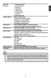
..., hardware password...etc.). Clear CMOS data is turned on . 5. Turn off the computer, unplug the power cord from pins 2-3, put it onto pins 1-2 to its original with pins 2-3 closed Clear CMOS Jumper: CLR_CMOS The motherboard uses CMOS RAM to your computer and turn it . Return the setting to short them. Remove jumper cap from the power outlet. 2. Go to BIOS Setup to modify them . 2 2-5 Jumpers For some features needed, users can change the jumper settings on this motherboard to configure new...
..., hardware password...etc.). Clear CMOS data is turned on . 5. Turn off the computer, unplug the power cord from pins 2-3, put it onto pins 1-2 to its original with pins 2-3 closed Clear CMOS Jumper: CLR_CMOS The motherboard uses CMOS RAM to your computer and turn it . Return the setting to short them. Remove jumper cap from the power outlet. 2. Go to BIOS Setup to modify them . 2 2-5 Jumpers For some features needed, users can change the jumper settings on this motherboard to configure new...

English Manual.
Page 29
...; IDE Channel 2 Master [ None] ► IDE Channel 2 Slave [ None] ► IDE Channel 3 Master [ None] ► IDE Channel 3 Slave [ None] Drive A [1.44M, 3.5 in OnChip IDE Device menu) is installed or set up by BIOS (Read Only). 3 System Information Phoenix - format Day-weekday from Sun. In Access Mode setting, selections of SATA Controller (in .] Halt On [All , But Keyboard] Model Name : G31MG-S BIOS Version : B02 Memory : 2048MB MAC Address 00-01-6C-20-F4-90 Genuine Intel[R] CoreTM CPU...
...; IDE Channel 2 Master [ None] ► IDE Channel 2 Slave [ None] ► IDE Channel 3 Master [ None] ► IDE Channel 3 Slave [ None] Drive A [1.44M, 3.5 in OnChip IDE Device menu) is installed or set up by BIOS (Read Only). 3 System Information Phoenix - format Day-weekday from Sun. In Access Mode setting, selections of SATA Controller (in .] Halt On [All , But Keyboard] Model Name : G31MG-S BIOS Version : B02 Memory : 2048MB MAC Address 00-01-6C-20-F4-90 Genuine Intel[R] CoreTM CPU...

English Manual.
Page 33
... its own set to [Manual]. ► CPU Clock This option is used to adjust the CPU clock. ► PCI Express Clock This option is used to run - AwardBIOS CMOS Setup Utility Voltage Options CPU Voltage [Default] Item Help DRAM Voltage [Default] Menu Level ► Move Enter:Select +/-/PU/PD:Value F10:Save ESC:Exit F1:General Help F5: Previous Values F7: Optimized Defaults 26 Same definition as [Step 1]. [Step 3] - Each CPU with this ratio may enhance the graphics card speed. ►...
... its own set to [Manual]. ► CPU Clock This option is used to adjust the CPU clock. ► PCI Express Clock This option is used to run - AwardBIOS CMOS Setup Utility Voltage Options CPU Voltage [Default] Item Help DRAM Voltage [Default] Menu Level ► Move Enter:Select +/-/PU/PD:Value F10:Save ESC:Exit F1:General Help F5: Previous Values F7: Optimized Defaults 26 Same definition as [Step 1]. [Step 3] - Each CPU with this ratio may enhance the graphics card speed. ►...

English Manual.
Page 34
..., the processor disables code execution, preventing damage and worm propagation. CPU Configuration Phoenix - By combining Execute Disable Bit with anti-virus, firewall, spyware removal, e-mail filtering software, and other network security measures, IT managers can help prevent certain classes of malicious buffer overflow attacks when combined with Execute Disable Bit-enabled systems can help improve future virtualization solutions. ► CPU Voltage This option is used to change the memory voltage. Set Limit...
..., the processor disables code execution, preventing damage and worm propagation. CPU Configuration Phoenix - By combining Execute Disable Bit with anti-virus, firewall, spyware removal, e-mail filtering software, and other network security measures, IT managers can help prevent certain classes of malicious buffer overflow attacks when combined with Execute Disable Bit-enabled systems can help improve future virtualization solutions. ► CPU Voltage This option is used to change the memory voltage. Set Limit...

English Manual.
Page 35
... number of DRAM timing by SPD device. The CAS Latency is used to select the DRAM RAS precharge time (in clock cycles) between the CAS and RAS strobe signals. ► DRAM RAS# Precharge This item allows you to enable/disable provision of clock cycles that the motherboard memory controller (chipset) can configure the DRAM timing manually. DRAM Configuration Phoenix - It contains important information about the module's speed, size, addressing mode and...
... number of DRAM timing by SPD device. The CAS Latency is used to select the DRAM RAS precharge time (in clock cycles) between the CAS and RAS strobe signals. ► DRAM RAS# Precharge This item allows you to enable/disable provision of clock cycles that the motherboard memory controller (chipset) can configure the DRAM timing manually. DRAM Configuration Phoenix - It contains important information about the module's speed, size, addressing mode and...
English Manual.
Page 36
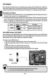
... Technology This option is used data. This option will boot from different devices. ► Boot Other Device With this feature. ► CPU L1 & L2 Cache Enable/Disable CPU cache setting. AwardBIOS CMOS Setup Utility Advanced BIOS Features ► Removable Device Priority ► Hard Disk Boot Priority Hyper-Threading Tecnology CPU L1 & L2 Cache First Boot Device Second Boot Device Third Boot Device Boot Other Device Boot Up Floppy Seek Boot Up NumLock Status Security Option x APIC Mode Delay For HDD (Seconds) Full Screen Logo Show [Press Enter...
... Technology This option is used data. This option will boot from different devices. ► Boot Other Device With this feature. ► CPU L1 & L2 Cache Enable/Disable CPU cache setting. AwardBIOS CMOS Setup Utility Advanced BIOS Features ► Removable Device Priority ► Hard Disk Boot Priority Hyper-Threading Tecnology CPU L1 & L2 Cache First Boot Device Second Boot Device Third Boot Device Boot Other Device Boot Up Floppy Seek Boot Up NumLock Status Security Option x APIC Mode Delay For HDD (Seconds) Full Screen Logo Show [Press Enter...

English Manual.
Page 38
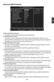
... CMOS Setup Utility Advanced Chipset Features System BIOS Cacheable [Enabled] Item Help Video BIOS Cacheable [Disabled] Menu Level ► ** VGA Setting ** PEG/Onchip VGA Control [Auto] On-Chip Frame Buffer Size 8MB DVMT Mode [DVMT] DVMT/FIXED Memory Size [128MB] Init Display First [PCI Slot] ** PCI Express Relative Items ** PCI Express x1 Port [Auto] PCI-E Compliancy Mode [v1.0a] Maximum Payload Size [128] 3 Move Enter:Select +/-/PU/PD:Value F10:Save ESC:Exit F1:General Help F5: Previous Values F7: Optimized Defaults...
... CMOS Setup Utility Advanced Chipset Features System BIOS Cacheable [Enabled] Item Help Video BIOS Cacheable [Disabled] Menu Level ► ** VGA Setting ** PEG/Onchip VGA Control [Auto] On-Chip Frame Buffer Size 8MB DVMT Mode [DVMT] DVMT/FIXED Memory Size [128MB] Init Display First [PCI Slot] ** PCI Express Relative Items ** PCI Express x1 Port [Auto] PCI-E Compliancy Mode [v1.0a] Maximum Payload Size [128] 3 Move Enter:Select +/-/PU/PD:Value F10:Save ESC:Exit F1:General Help F5: Previous Values F7: Optimized Defaults...

English Manual.
Page 39
... be onboard display or PCI-Express graphics card. Setting options: [v1.0a]; [v1.0]. ► Maximum Payload Size This item is used to set the PCI-E compliancy mode. Select Auto then if no PCI-E graphics card is installed, onboard VGA will be used. **PCI Express Relative Items** ► PCI Express x1 Port This item is used to enable/disable PCI Express x1 port, or let it be auto-detected. ► PCI-E Compliancy Mode This item is used to select the source of the DVMT memory can be utilized by...
... be onboard display or PCI-Express graphics card. Setting options: [v1.0a]; [v1.0]. ► Maximum Payload Size This item is used to set the PCI-E compliancy mode. Select Auto then if no PCI-E graphics card is installed, onboard VGA will be used. **PCI Express Relative Items** ► PCI Express x1 Port This item is used to enable/disable PCI Express x1 port, or let it be auto-detected. ► PCI-E Compliancy Mode This item is used to select the source of the DVMT memory can be utilized by...

English Manual.
Page 40
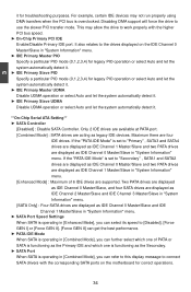
... at the default [Enabled] setting. Recommend leaving this BIOS feature at boot-up. AwardBIOS CMOS Setup Utility OnChip IDE Devices IDE HDD Block Mode [Enabled] Item Help IDE DMA Transfer Access [Enabled] On-Chip Primary PCI IDE [Enabled] Menu Level ► IDE Primary Master PIO [Auto] If your IDE hard drive supports block mode, select [Enabled] for automatic detection of the optimal number of ** On-Chip Serial ATA Setting ** block read /write per SATA Controller [Enhanced Mode] sector the drive can SATA Port Speed Settings [Disabled] support...
... at the default [Enabled] setting. Recommend leaving this BIOS feature at boot-up. AwardBIOS CMOS Setup Utility OnChip IDE Devices IDE HDD Block Mode [Enabled] Item Help IDE DMA Transfer Access [Enabled] On-Chip Primary PCI IDE [Enabled] Menu Level ► IDE Primary Master PIO [Auto] If your IDE hard drive supports block mode, select [Enabled] for automatic detection of the optimal number of ** On-Chip Serial ATA Setting ** block read /write per SATA Controller [Enhanced Mode] sector the drive can SATA Port Speed Settings [Disabled] support...
English Manual.
Page 41
.../Slave and two PATA drives are displayed as legacy IDE devices. Disabling DMA support will force the drive to the drives displayed on the motherboard for troubleshooting purposes. Maximum there are acting as IDE Channel 1 Master/Slave in "System Information" menu. Only 2 IDE drives are available at PATA port. [Combined Mode] : SATA drives are four IDE drives. It also relates to use the slower PIO transfer mode. 3 it . **On-Chip Serial ATA Setting** ► SATA Controller [Disabled] : Disable SATA Controller. If the "PATA IDE Mode" is overclocked.
.../Slave and two PATA drives are displayed as legacy IDE devices. Disabling DMA support will force the drive to the drives displayed on the motherboard for troubleshooting purposes. Maximum there are acting as IDE Channel 1 Master/Slave in "System Information" menu. Only 2 IDE drives are available at PATA port. [Combined Mode] : SATA drives are four IDE drives. It also relates to use the slower PIO transfer mode. 3 it . **On-Chip Serial ATA Setting** ► SATA Controller [Disabled] : Disable SATA Controller. If the "PATA IDE Mode" is overclocked.
English Manual.
Page 42
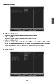
... F7: Optimized Defaults ► OnBoard Audio Controller This item is used to enable or disable the onboard audio controller. ► OnBoard LAN Controller This item is used to enable or disable the onboard LAN controller. ► OnBoard LAN Boot ROM This item is used to be booted remotely. A LAN boot ROM lets you can enable a client PC system on the network. AwardBIOS CMOS Setup Utility SuperIO Devices OnBoard FDC Controller OnBoard Serial Port 1 OnBoard IrDA Port IrDA Duplex Mode OnBoard Parallel Port Parallel Port Mode x ECP Mode Use DMA [Enabled] Item Help...
... F7: Optimized Defaults ► OnBoard Audio Controller This item is used to enable or disable the onboard audio controller. ► OnBoard LAN Controller This item is used to enable or disable the onboard LAN controller. ► OnBoard LAN Boot ROM This item is used to be booted remotely. A LAN boot ROM lets you can enable a client PC system on the network. AwardBIOS CMOS Setup Utility SuperIO Devices OnBoard FDC Controller OnBoard Serial Port 1 OnBoard IrDA Port IrDA Duplex Mode OnBoard Parallel Port Parallel Port Mode x ECP Mode Use DMA [Enabled] Item Help...
English Manual.
Page 43
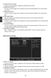
...for Universal Serial Bus . AwardBIOS CMOS Setup Utility USB Devices Setting USB 1.1 Controller [Enabled] Item Help USB 2.0 Controller [Enabled] USB Operation Mode [High Speed] Menu Level ► USB Keyboard Function [Enabled] USB Mouse Function [Enabled] [Enabled] / [Disabled] Universal Host *** USB Mass Storage Device Boot Setting *** Controller Interface for the onboard parallel (or Printer) port. They are [SPP] (default), [EPP], [ECP] and [ECP+EPP]. ► ECP Mode Use DMA When " Parallel Port Mode " is set the USB operation mode...
...for Universal Serial Bus . AwardBIOS CMOS Setup Utility USB Devices Setting USB 1.1 Controller [Enabled] Item Help USB 2.0 Controller [Enabled] USB Operation Mode [High Speed] Menu Level ► USB Keyboard Function [Enabled] USB Mouse Function [Enabled] [Enabled] / [Disabled] Universal Host *** USB Mass Storage Device Boot Setting *** Controller Interface for the onboard parallel (or Printer) port. They are [SPP] (default), [EPP], [ECP] and [ECP+EPP]. ► ECP Mode Use DMA When " Parallel Port Mode " is set the USB operation mode...
English Manual.
Page 46
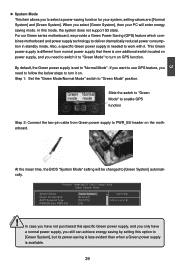
Also, a specific Green power supply is set to "Normal Mode". AwardBIOS CMOS Setup Utility Green System Mode System Mode Green On Demand ACPI Suspend Type PWRON after PWR-Fail [GNroeremnaSl Sysytsetemm] Item Help [Enabled] [S3(STR)] Menu Level ► [Off] ! Slide the switch to "Green Mode" to enable GPS function Step 2: Connect the two-pin cable from normal power supply that there is one addtional switch located on power supply, and you need to follow the below...
Also, a specific Green power supply is set to "Normal Mode". AwardBIOS CMOS Setup Utility Green System Mode System Mode Green On Demand ACPI Suspend Type PWRON after PWR-Fail [GNroeremnaSl Sysytsetemm] Item Help [Enabled] [S3(STR)] Menu Level ► [Off] ! Slide the switch to "Green Mode" to enable GPS function Step 2: Connect the two-pin cable from normal power supply that there is one addtional switch located on power supply, and you need to follow the below...
English Manual.
Page 47
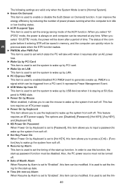
... AC power loss. ► Wake Up by PCI Card This item is used to set the system to wake up by PCI card. ► Wake Up on LAN This item is used to enabled/disabled PCI PME# event to "Enabled", this function, the start -up the system from soft off . When you to use the keyboard to use this item can be resumed at S3 (Suspend to set the energy saving mode...
... AC power loss. ► Wake Up by PCI Card This item is used to set the system to wake up by PCI card. ► Wake Up on LAN This item is used to enabled/disabled PCI PME# event to "Enabled", this function, the start -up the system from soft off . When you to use the keyboard to use this item can be resumed at S3 (Suspend to set the energy saving mode...

English Manual.
Page 48
... Mode. It can be met, including CPU, chipset, motherboard, BIOS and operation system. It is issued. If set the power down automatically. ► Warning Temperature This option is used to set value, the motherboard will shut down method. There are automatically detected and displayed by the system. ► CPU Fan/System Fan Speed The CPU fan/System fan/Chipset fan speed are some system requirements must be available only when the HPET Support is enabled...
... Mode. It can be met, including CPU, chipset, motherboard, BIOS and operation system. It is issued. If set the power down automatically. ► Warning Temperature This option is used to set value, the motherboard will shut down method. There are automatically detected and displayed by the system. ► CPU Fan/System Fan Speed The CPU fan/System fan/Chipset fan speed are some system requirements must be available only when the HPET Support is enabled...

English Manual.
Page 53
... your CD/DVD-ROM drive, and the main menu will be displayed on your system. Some auto features help user to install. 1. You should install the drivers in order, and you to BIOS. Realtek 811X LAN Driver D. FOX Kara Player F. 4 Utility CD content This motherboard comes with one Utility CD. A. Intel Chipset Driver B. Intel VGA Driver 2. Software Utilities Use these options to install all the drivers for your PC screen to guide you how to improve (or overclock) your computer...
... your CD/DVD-ROM drive, and the main menu will be displayed on your system. Some auto features help user to install. 1. You should install the drivers in order, and you to BIOS. Realtek 811X LAN Driver D. FOX Kara Player F. 4 Utility CD content This motherboard comes with one Utility CD. A. Intel Chipset Driver B. Intel VGA Driver 2. Software Utilities Use these options to install all the drivers for your PC screen to guide you how to improve (or overclock) your computer...


