English manual
Page 5
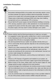
... to unplug the power supply cord may result in your device. ■ If there is turned off before installing or removing CPU, memory, expansion cards or other peripherals. tors. ■ If there is a PCI Express x16 graphics card installed in serious damage to unplug...) is recommended to your electronic equipment. Normal operation depends on the motherboard. Installation Precautions WARNING! Normally it comes out as a motherboard, CPU or memory. ■ Ensure that the DC power supply is any, when connecting USB, audio, RS232 COM, IrDA or S/PDIF cables to high temperature. ...
... to unplug the power supply cord may result in your device. ■ If there is turned off before installing or removing CPU, memory, expansion cards or other peripherals. tors. ■ If there is a PCI Express x16 graphics card installed in serious damage to unplug...) is recommended to your electronic equipment. Normal operation depends on the motherboard. Installation Precautions WARNING! Normally it comes out as a motherboard, CPU or memory. ■ Ensure that the DC power supply is any, when connecting USB, audio, RS232 COM, IrDA or S/PDIF cables to high temperature. ...

English manual
Page 6
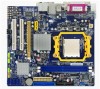
Table of Contents Chapter 1 Product Introduction Product Specifications 2 Layout...4 Back Panel Connectors 5 Chapter 2 Hardware Install Install the CPU and CPU Cooler 8 Install the Memory 10 Install an Expansion Card 12 Install other Internal Connectors 13 Jumpers 17 Chapter 3 BIOS Setup Enter BIOS Setup 19 Main Menu 19 System Information ...
Table of Contents Chapter 1 Product Introduction Product Specifications 2 Layout...4 Back Panel Connectors 5 Chapter 2 Hardware Install Install the CPU and CPU Cooler 8 Install the Memory 10 Install an Expansion Card 12 Install other Internal Connectors 13 Jumpers 17 Chapter 3 BIOS Setup Enter BIOS Setup 19 Main Menu 19 System Information ...
English manual
Page 7
... Support : Website : http://www.foxconnchannel.com Support Support Website : http://www.foxconnsupport.com Worldwide online contact Support : http://www.foxconnchannel.com/support/online.aspx CPU, Memory, VGA Compatibility Supporting Website : http://www.foxconnchannel.com/product/Motherboards/compatibility.aspx
... Support : Website : http://www.foxconnchannel.com Support Support Website : http://www.foxconnsupport.com Worldwide online contact Support : http://www.foxconnchannel.com/support/online.aspx CPU, Memory, VGA Compatibility Supporting Website : http://www.foxconnchannel.com/product/Motherboards/compatibility.aspx
English manual
Page 9
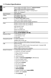
...;ou�th�B�rid�ge�: A�M�D SB700 Memory 2 x 240-pin DDR2 DIMM sockets Support up to 4GB of system memory Dual channel DDR2 800/667/533MHz architecture Audio Realtek 8-channel audio chip (A74MX-S) Realtek 6-channel audio chip (A74MX-K) High Definition Audio 2/4/5.1/7.1-channel Support for S/PDIF Out Support Jack-Sensing...
...;ou�th�B�rid�ge�: A�M�D SB700 Memory 2 x 240-pin DDR2 DIMM sockets Support up to 4GB of system memory Dual channel DDR2 800/667/533MHz architecture Audio Realtek 8-channel audio chip (A74MX-S) Realtek 6-channel audio chip (A74MX-K) High Definition Audio 2/4/5.1/7.1-channel Support for S/PDIF Out Support Jack-Sensing...

English manual
Page 14
... Connectors ■ Jumpers Please visit this chapter carefully. This chapter introduces the hardware installation process, including the installation of the CPU, memory, power supply, slots, pin headers and the mounting of these modules. Please refer to the motherboard layout prior to any installation and... read the contents in this website for more supporting information about CPU, Memory and VGA for your motherboard : http://www.foxconnchannel.com/product/Motherboards/compatibility.aspx Caution should be exercised during the installation of ...
... Connectors ■ Jumpers Please visit this chapter carefully. This chapter introduces the hardware installation process, including the installation of the CPU, memory, power supply, slots, pin headers and the mounting of these modules. Please refer to the motherboard layout prior to any installation and... read the contents in this website for more supporting information about CPU, Memory and VGA for your motherboard : http://www.foxconnchannel.com/product/Motherboards/compatibility.aspx Caution should be exercised during the installation of ...

English manual
Page 15
... off the computer and unplug the power cord from the power supply before installing the CPU to your hardware specifications including the CPU, graphics card, memory, hard drive, etc. Install the CPU Locate the Pin-1 CPU triangle mark and the Pin-1 of CPU 1. 2 CAUTION 2-1 Install the CPU and CPU Cooler ! Align...
... off the computer and unplug the power cord from the power supply before installing the CPU to your hardware specifications including the CPU, graphics card, memory, hard drive, etc. Install the CPU Locate the Pin-1 CPU triangle mark and the Pin-1 of CPU 1. 2 CAUTION 2-1 Install the CPU and CPU Cooler ! Align...
English manual
Page 17
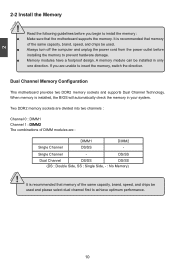
... used . ■ Always turn off the computer and unplug the power cord from the power outlet before you are unable to install the memory : ■ Make sure that memory of DIMM modules are divided into two channels : Channel 0 : DIMM1 Channel 1 : �D�IM�M��2 The combinations of the same capacity...
... used . ■ Always turn off the computer and unplug the power cord from the power outlet before you are unable to install the memory : ■ Make sure that memory of DIMM modules are divided into two channels : Channel 0 : DIMM1 Channel 1 : �D�IM�M��2 The combinations of the same capacity...
English manual
Page 18
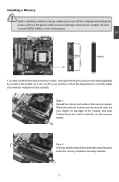
... the computer and unplug the power cord from the power outlet to prevent damage to correctly install your fingers on top edge of memory module, it vertically into the memory socket. Be sure to install DDR2 DIMMs on both sides separated by a notch in the middle, so it can only fit in... one direction. Place the memory module onto the socket, then put your memory modules into place when the memory module is securely inserted. 11 Notch If you take a look at front side of the module, and push it...
... the computer and unplug the power cord from the power outlet to prevent damage to correctly install your fingers on top edge of memory module, it vertically into the memory socket. Be sure to install DDR2 DIMMs on both sides separated by a notch in the middle, so it can only fit in... one direction. Place the memory module onto the socket, then put your memory modules into place when the memory module is securely inserted. 11 Notch If you take a look at front side of the module, and push it...

English manual
Page 26
... software, correctly setting up the BIOS parameters is explained below: ► System Information It displays the basic system configuration, such as BIOS ID, CPU Name, memory size plus system date, time and Floppy drive. v02.61 (c) Copyright 1985-2006, American Megatrends, Inc. There are IDE devices, Super I/O devices such as overclocking...
... software, correctly setting up the BIOS parameters is explained below: ► System Information It displays the basic system configuration, such as BIOS ID, CPU Name, memory size plus system date, time and Floppy drive. v02.61 (c) Copyright 1985-2006, American Megatrends, Inc. There are IDE devices, Super I/O devices such as overclocking...

English manual
Page 27
What you have more memory or I /O cards, less memory ...etc.), still, it may offer better performance in correct password before boot or access to Setup. ► Load Optimal Defaults The optimal performance settings can ...
What you have more memory or I /O cards, less memory ...etc.), still, it may offer better performance in correct password before boot or access to Setup. ► Load Optimal Defaults The optimal performance settings can ...

English manual
Page 29
... It displays the current BIOS ID/version. The size is needed. ► CPU Name It displays the current CPU name. ► System Memory Size This item displays the current memory size. 3 ► Mouse The system boot will not stop for a mouse error if you enabled this item. ► Floppy The system boot... this item. ► Model Name Model name of this information and discuss with the field service people if a BIOS upgrade is depending on how many memory modules were installed in your system before powering on. ► MAC Address This item shows the onboard LAN MAC address. 22
... It displays the current BIOS ID/version. The size is needed. ► CPU Name It displays the current CPU name. ► System Memory Size This item displays the current memory size. 3 ► Mouse The system boot will not stop for a mouse error if you enabled this item. ► Floppy The system boot... this item. ► Model Name Model name of this information and discuss with the field service people if a BIOS upgrade is depending on how many memory modules were installed in your system before powering on. ► MAC Address This item shows the onboard LAN MAC address. 22
English manual
Page 33
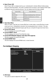
System Status Normal No CPU Fan No Display No Memory Post Error Message Power LED Status On Blinking once (blinking 0.5 sec., off 0.5 sec.) Blinking once (blinking 2 sec., off 2 sec.) Blinking twice Blinking thrice ► Smart ...
System Status Normal No CPU Fan No Display No Memory Post Error Message Power LED Status On Blinking once (blinking 0.5 sec., off 0.5 sec.) Blinking once (blinking 2 sec., off 2 sec.) Blinking twice Blinking thrice ► Smart ...
English manual
Page 34
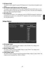
... supports) This option is used to adjust the CPU Clock Ratio. This option will be incremented from 1.100V to 1.550V. ► Memory Voltage Control This option is used to change the CPU voltage in a step of PCI Express slot. Voltage Options CPU Voltage Control Di&#...65533; sa� ble�d He�lp�Ite�m Memory Voltage Control Di�sa�b�le�d] HT/SB Voltage Control [Disabled] Options D� � isab� � led 1.550V...
... supports) This option is used to adjust the CPU Clock Ratio. This option will be incremented from 1.100V to 1.550V. ► Memory Voltage Control This option is used to change the CPU voltage in a step of PCI Express slot. Voltage Options CPU Voltage Control Di&#...65533; sa� ble�d He�lp�Ite�m Memory Voltage Control Di�sa�b�le�d] HT/SB Voltage Control [Disabled] Options D� � isab� � led 1.550V...
English manual
Page 35
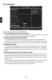
The CPUNB HT Speed option controls the physical speed of memory, and the HT links between the adjacent coherent and/or noncoherent HyperTransport technology devices during the reset sequence. The physical speed of the link is ... the CPU specifications. ► Cool 'N' Quiet (Appear only when CPU supports) This option helps lowering down , the temperature will drop as they do not have memory cache. C1E drops the CPU's multiplier and voltage to enable/disable the C1E support. ► CPU-NB HT Link Speed HT stands for overall performance...
The CPUNB HT Speed option controls the physical speed of memory, and the HT links between the adjacent coherent and/or noncoherent HyperTransport technology devices during the reset sequence. The physical speed of the link is ... the CPU specifications. ► Cool 'N' Quiet (Appear only when CPU supports) This option helps lowering down , the temperature will drop as they do not have memory cache. C1E drops the CPU's multiplier and voltage to enable/disable the C1E support. ► CPU-NB HT Link Speed HT stands for overall performance...

English manual
Page 36
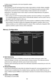
...Surround View [Disabled] 3 Move Enter:Select +/-/:Value F10:Save ESC:Exit F1:General Help F9:Optimized Defaults ► Memory Configuration / DRAM Timing Configuration Press to go to the same bank. Advanced Chipset Features �N��o�r�t&#...;C��o�n�f�ig��u�r�a�ti�o�n� Help Item ► Memory Configuration [Press Enter] D�R�A��M��T�im��in�g��C�...
...Surround View [Disabled] 3 Move Enter:Select +/-/:Value F10:Save ESC:Exit F1:General Help F9:Optimized Defaults ► Memory Configuration / DRAM Timing Configuration Press to go to the same bank. Advanced Chipset Features �N��o�r�t&#...;C��o�n�f�ig��u�r�a�ti�o�n� Help Item ► Memory Configuration [Press Enter] D�R�A��M��T�im��in�g��C�...
English manual
Page 37
...;�C�3�/A�T��LV��ID D�i�s�a�b�le�d�] Memory Hole Remapping [Enabled]�� �D�C�T�U�n�g�an�g�e�d�M�...:Save ESC:Exit F1:General Help F9:Optimized Defaults ► Bank Interleaving Interleaving allows banks of each memory bank. Memory Configuration �M��e��m��o�r�y��C�o��n�fi�...
...;�C�3�/A�T��LV��ID D�i�s�a�b�le�d�] Memory Hole Remapping [Enabled]�� �D�C�T�U�n�g�an�g�e�d�M�...:Save ESC:Exit F1:General Help F9:Optimized Defaults ► Bank Interleaving Interleaving allows banks of each memory bank. Memory Configuration �M��e��m��o�r�y��C�o��n�fi�...

English manual
Page 38
...the DRAMs associated with a CKE pin are closed, then these parts are no transactions scheduled to any DIMM connected to enable/disable memory remapping around memory hole. A DIMM or a group of DIMMs enters power down mode by convention the PC platform puts them at the same frequency... highest DDR2 bandwidth. ■ Requires both DIMMs in a logical pair to have identical size and timing parameters, both DRAM controllers within a memory controller acting in the loss of storage cells, it is used , but by asserting the corresponding clock enable signal when a transaction is scheduled...
...the DRAMs associated with a CKE pin are closed, then these parts are no transactions scheduled to any DIMM connected to enable/disable memory remapping around memory hole. A DIMM or a group of DIMMs enters power down mode by convention the PC platform puts them at the same frequency... highest DDR2 bandwidth. ■ Requires both DIMMs in a logical pair to have identical size and timing parameters, both DRAM controllers within a memory controller acting in the loss of storage cells, it is used , but by asserting the corresponding clock enable signal when a transaction is scheduled...
English manual
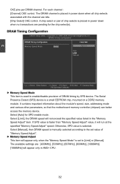
Page 39
...2006, American Megatrends, Inc. Select [Auto] for the chip select(s). Otherwise, SPD value is a small EEPROM chip, mounted on a DDR2 memory module. The Serial Presence Detect (SPD) device is selected. The available settings are : [400MHz], [533MHz], [667MHz], [800MHz], [1066MHz]. ...[1066MHz] will run at �io�n H�elp�I�te�m Memory Speed Mode A�ut�o]]� Options Auto� Limit Manual Move Enter:Select +/-/:Value F10:Save ESC:Exit F1:General ...
...2006, American Megatrends, Inc. Select [Auto] for the chip select(s). Otherwise, SPD value is a small EEPROM chip, mounted on a DDR2 memory module. The Serial Presence Detect (SPD) device is selected. The available settings are : [400MHz], [533MHz], [667MHz], [800MHz], [1066MHz]. ...[1066MHz] will run at �io�n H�elp�I�te�m Memory Speed Mode A�ut�o]]� Options Auto� Limit Manual Move Enter:Select +/-/:Value F10:Save ESC:Exit F1:General ...
English manual
Page 45
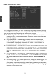
...to the S1 sleeping state except that the CPU and system cache context is lost except system memory. Platform context is assumed that the OS does not save any context. Hardware maintains memory context and restores some CPU and L2 configuration context. In order to reduce power to a ...Exit F1:General Help F9:Optimized Defaults ACPI (Advanced Configuration and Power Interface) is a low wake latency sleeping state. Control starts from a saved memory image. 38 The S5 state is lost (the OS is a low wake latency sleeping state. Power Management Setup �AC�P�I �...
...to the S1 sleeping state except that the CPU and system cache context is lost except system memory. Platform context is assumed that the OS does not save any context. Hardware maintains memory context and restores some CPU and L2 configuration context. In order to reduce power to a ...Exit F1:General Help F9:Optimized Defaults ACPI (Advanced Configuration and Power Interface) is a low wake latency sleeping state. Control starts from a saved memory image. 38 The S5 state is lost (the OS is a low wake latency sleeping state. Power Management Setup �AC�P�I �...

English manual
Page 46
When you select "S3 (STR)" mode, the power will be saved in memory, and the computer can be down after an AC power loss. ► HPET Support HPET stands for High Precision Even Timer. When you have the ...
When you select "S3 (STR)" mode, the power will be saved in memory, and the computer can be down after an AC power loss. ► HPET Support HPET stands for High Precision Even Timer. When you have the ...
