
English Manual.
Page 6
... Install the Memory 10 Install an Expansion Card 12 Install other Internal Connectors 13 Jumpers 17 Chapter 3 BIOS Setup Enter BIOS Setup 19 Main Menu 19 System Information 21 Advanced BIOS Features 23 Fox Central Control Unit 25 Advanced Chipset Features 29 Integrated Peripherals 33 Power Management Setup 38... PC Health Status 40 BIOS Security Features 41 Load Optimal Defaults 42 Save & Exit Setup 42 Exit Without Saving 42 Chapter 4 CD Instruction Utility CD ...
... Install the Memory 10 Install an Expansion Card 12 Install other Internal Connectors 13 Jumpers 17 Chapter 3 BIOS Setup Enter BIOS Setup 19 Main Menu 19 System Information 21 Advanced BIOS Features 23 Fox Central Control Unit 25 Advanced Chipset Features 29 Integrated Peripherals 33 Power Management Setup 38... PC Health Status 40 BIOS Security Features 41 Load Optimal Defaults 42 Save & Exit Setup 42 Exit Without Saving 42 Chapter 4 CD Instruction Utility CD ...

English Manual.
Page 7
... 65 FOX LOGO 66 FOX DMI 67 Chapter 5 RAID Configuration RAID Configuration Introduction 70 FastBuild Driver 72 Create a RAID Driver Diskette 74 RAID Enable in BIOS 76 Select a RAID Array for Use 76 Install a New Windows XP 89 Setting Up a Non-Bootable RAID Array 93 Technical Support : Support Website : http://www...
... 65 FOX LOGO 66 FOX DMI 67 Chapter 5 RAID Configuration RAID Configuration Introduction 70 FastBuild Driver 72 Create a RAID Driver Diskette 74 RAID Enable in BIOS 76 Select a RAID Array for Use 76 Install a New Windows XP 89 Setting Up a Non-Bootable RAID Array 93 Technical Support : Support Website : http://www...
English Manual.
Page 17
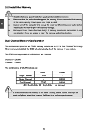
... install the memory : ■ Make sure that memory of the same capacity, brand, speed, and chips be installed in your system. It is installed, the BIOS will automatically check the memory in only one direction.
... install the memory : ■ Make sure that memory of the same capacity, brand, speed, and chips be installed in your system. It is installed, the BIOS will automatically check the memory in only one direction.

English Manual.
Page 19
...8226; Removing the Card: Push the latch at the end of the PCI Express x16 slot to prevent hardware damage. If necessary, go to BIOS Setup to correctly install your expansion card. ■ Always turn off the computer and unplug the power cord from the power outlet before installing ... the driver provided with your expansion card in your card. PCI Express x1 PCI Express x16 PCI Follow the steps below to make any required BIOS changes for your computer. Installing and Removing a PCI Express x16 Graphics Card : • Installing a Graphics Card: Gently insert the graphics card into the ...
...8226; Removing the Card: Push the latch at the end of the PCI Express x16 slot to prevent hardware damage. If necessary, go to BIOS Setup to correctly install your expansion card. ■ Always turn off the computer and unplug the power cord from the power outlet before installing ... the driver provided with your expansion card in your card. PCI Express x1 PCI Express x16 PCI Follow the steps below to make any required BIOS changes for your computer. Installing and Removing a PCI Express x16 Graphics Card : • Installing a Graphics Card: Gently insert the graphics card into the ...

English Manual.
Page 23
... sleeping states. 1 GND POWER SENSE CONTROL CPU_FAN/SYS_FAN LPT Connector : LPT The connector supports parallel port which can be connected to connect speaker of the BIOS Setup.
... sleeping states. 1 GND POWER SENSE CONTROL CPU_FAN/SYS_FAN LPT Connector : LPT The connector supports parallel port which can be connected to connect speaker of the BIOS Setup.

English Manual.
Page 24
...it onto pins 1-2 to short them . This will clear CMOS data. 3. Go to BIOS Setup to configure new system as described in the power cord to factory default when the BIOS settings were mistakenly modified. 2 2-5 Jumpers For some features needed, users can prevent hazardous ... as "1". 2. The shorting can be done by touching two pins by a screwdriver for a few seconds, but using jumper cap is simply labeled as BIOS data, date, time information, hardware password...etc.). Remove jumper cap from the power outlet. 2. Jumper 1 Diagram 1 1 Definition 1-2 2-3 Description Set Pin...
...it onto pins 1-2 to short them . This will clear CMOS data. 3. Go to BIOS Setup to configure new system as described in the power cord to factory default when the BIOS settings were mistakenly modified. 2 2-5 Jumpers For some features needed, users can prevent hazardous ... as "1". 2. The shorting can be done by touching two pins by a screwdriver for a few seconds, but using jumper cap is simply labeled as BIOS data, date, time information, hardware password...etc.). Remove jumper cap from the power outlet. 2. Jumper 1 Diagram 1 1 Definition 1-2 2-3 Description Set Pin...

English Manual.
Page 25
...the following cases occur: 1. You have to run the Setup Program when the following information : ■ Enter BIOS Setup ■ Main Menu ■ System Information ■ Advanced BIOS Features ■ Fox Central Control Unit ■ Advanced Chipset Features ■ Integrated Peripherals ■ Power Management ...Defaults ■ Save & Exit Setup ■ Exit Without Saving Since BIOS could be updated some other times, the BIOS information described in this manual will remain consistent with the newly released BIOS at any given time in the future. This chapter tells how to change...
...the following cases occur: 1. You have to run the Setup Program when the following information : ■ Enter BIOS Setup ■ Main Menu ■ System Information ■ Advanced BIOS Features ■ Fox Central Control Unit ■ Advanced Chipset Features ■ Integrated Peripherals ■ Power Management ...Defaults ■ Save & Exit Setup ■ Exit Without Saving Since BIOS could be updated some other times, the BIOS information described in this manual will remain consistent with the newly released BIOS at any given time in the future. This chapter tells how to change...

English Manual.
Page 26
...to select a specific item and press to go to maintain optimal system performance. CMOS Setup Utility - Each item in the BIOS Setup, and we shall not be set up through this menu. etc. 19 Display System Information... Copyright (C) 1985-2006, ...American Megatrends, Inc. ► System Information ► PC Health Status ► Advanced BIOS Features ► BIOS Security Features ► Fox Central Control Unit Load Optimal Defaults ► Advanced Chipset Features Save & Exit Setup ► Integrated ...
...to select a specific item and press to go to maintain optimal system performance. CMOS Setup Utility - Each item in the BIOS Setup, and we shall not be set up through this menu. etc. 19 Display System Information... Copyright (C) 1985-2006, ...American Megatrends, Inc. ► System Information ► PC Health Status ► Advanced BIOS Features ► BIOS Security Features ► Fox Central Control Unit Load Optimal Defaults ► Advanced Chipset Features Save & Exit Setup ► Integrated ...

English Manual.
Page 27
... displays temperatures and voltages of your computer. It means, if your system loading is to adjust BIOS setting one by one, trial and error, to find out the best setting for your CPU/System. ► BIOS Security Features The Supervisor/User password can be set a password, the system will ask you to...
... displays temperatures and voltages of your computer. It means, if your system loading is to adjust BIOS setting one by one, trial and error, to find out the best setting for your CPU/System. ► BIOS Security Features The Supervisor/User password can be set a password, the system will ask you to...

English Manual.
Page 28
...select a field. The three fields of the setting are : : respectively. ► Primary/Secondary/Third IDE Master/Slave While entering setup, BIOS automatically detects the presence of IDE devices. This item displays the drive information of IDE devices. to Sat., this item. 21 Use the arrow...; Third IDE Slave [Not Detected] Halt On [All Errors But ...] Keyboard [Disabled] Mouse [Disabled] Floppy [Disabled] Model Name :A74ML-K BIOS ID :961F1D05 BIOS Version :08.00.14 CPU Name :AMD Athlon(tm) 64 X2 Dual Core Processor 5200+ Move Enter:Select +/-/:Value F10:Save ESC:...
...select a field. The three fields of the setting are : : respectively. ► Primary/Secondary/Third IDE Master/Slave While entering setup, BIOS automatically detects the presence of IDE devices. This item displays the drive information of IDE devices. to Sat., this item. 21 Use the arrow...; Third IDE Slave [Not Detected] Halt On [All Errors But ...] Keyboard [Disabled] Mouse [Disabled] Floppy [Disabled] Model Name :A74ML-K BIOS ID :961F1D05 BIOS Version :08.00.14 CPU Name :AMD Athlon(tm) 64 X2 Dual Core Processor 5200+ Move Enter:Select +/-/:Value F10:Save ESC:...

English Manual.
Page 29
... stop for a floppy error if you enabled this item. ► Model Name Model name of this information and discuss with the field service people if a BIOS upgrade is depending on how many memory modules were installed in your system before powering on. ► MAC Address This item shows the onboard LAN...; CPU Name It displays the current CPU name. ► System Memory Size This item displays the current memory size. User can check this product. ► BIOS ID/BIOS Version It displays the current...
... stop for a floppy error if you enabled this item. ► Model Name Model name of this information and discuss with the field service people if a BIOS upgrade is depending on how many memory modules were installed in your system before powering on. ► MAC Address This item shows the onboard LAN...; CPU Name It displays the current CPU name. ► System Memory Size This item displays the current memory size. User can check this product. ► BIOS ID/BIOS Version It displays the current...
English Manual.
Page 30
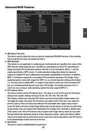
... the original specification. If your operating system comes with two or more processors. Copyright (C) 1985-2006, American Megatrends, Inc. Advanced BIOS Features IDE Detect Time Out MPS Revision PCI Latency Timer Quiet Boot Quick Boot Floppy Drive Seek Bootup Num-Lock ► Boot Device...select the time out value for MPS 1.4, you start facing problems like stuttering sound or a less responsive system, reduce the latency. Advanced BIOS Features CMOS Setup Utility - MPS version 1.4 adds extended configuration tables for a secondary PCI bus without requiring a PCI bridge. Low values for...
... the original specification. If your operating system comes with two or more processors. Copyright (C) 1985-2006, American Megatrends, Inc. Advanced BIOS Features IDE Detect Time Out MPS Revision PCI Latency Timer Quiet Boot Quick Boot Floppy Drive Seek Bootup Num-Lock ► Boot Device...select the time out value for MPS 1.4, you start facing problems like stuttering sound or a less responsive system, reduce the latency. Advanced BIOS Features CMOS Setup Utility - MPS version 1.4 adds extended configuration tables for a secondary PCI bus without requiring a PCI bridge. Low values for...

English Manual.
Page 31
...: Displays the normal POST messages. [Enabled] : Displays OEM customer logo instead of POST messages. ► Quick Boot While Enabled, this option allows BIOS to skip certain tests while booting, this menu by pressing . ► Hard Disk Drives This option is used to specify the boot priority sequence from...the keyboard Num Lock key is active when your system is used to boot the system. ► Floppy Drive Seek This item controls whether the BIOS will be checking for boot devices. The available settings are: On (default) and Off. ► Boot Device Priority This option is started. After...
...: Displays the normal POST messages. [Enabled] : Displays OEM customer logo instead of POST messages. ► Quick Boot While Enabled, this option allows BIOS to skip certain tests while booting, this menu by pressing . ► Hard Disk Drives This option is used to specify the boot priority sequence from...the keyboard Num Lock key is active when your system is used to boot the system. ► Floppy Drive Seek This item controls whether the BIOS will be checking for boot devices. The available settings are: On (default) and Off. ► Boot Device Priority This option is started. After...

English Manual.
Page 32
...-protection mechanism provided. Fox Central Control Unit CMOS Setup Utility - Copyright (C) 1985-2006, American Megatrends, Inc. Smart BIOS Smart Power LED [Disabled] Help Item Smart Boot Menu Current CPU Speed [Enabled] : 2700MHz Options Current FSB/HTT Clock : ...MHz Enabled Move Enter:Select +/-/:Value F10:Save ESC:Exit F1:General Help F9:Optimized Defaults 25 Fox Central Control Unit Super BIOS Protect Auto Detect PCI Clock ► Smart BIOS ► Fox Intelligent Stepping ► Voltage Options ► CPU Configuration [Disabled] Help Item [Disabled] [Press Enter]...
...-protection mechanism provided. Fox Central Control Unit CMOS Setup Utility - Copyright (C) 1985-2006, American Megatrends, Inc. Smart BIOS Smart Power LED [Disabled] Help Item Smart Boot Menu Current CPU Speed [Enabled] : 2700MHz Options Current FSB/HTT Clock : ...MHz Enabled Move Enter:Select +/-/:Value F10:Save ESC:Exit F1:General Help F9:Optimized Defaults 25 Fox Central Control Unit Super BIOS Protect Auto Detect PCI Clock ► Smart BIOS ► Fox Intelligent Stepping ► Voltage Options ► CPU Configuration [Disabled] Help Item [Disabled] [Press Enter]...

English Manual.
Page 37
When using a non-ATI PCI Express (PCIe) graphics card, SurroundView is not supported. Enabling SurroundView in the BIOS enables the integrated UMA graphics controller, which in the same bank. ► Channel Interleaving Dual channel (Interleaved) mode offers the highest throughput for real world ...
When using a non-ATI PCI Express (PCIe) graphics card, SurroundView is not supported. Enabling SurroundView in the BIOS enables the integrated UMA graphics controller, which in the same bank. ► Channel Interleaving Dual channel (Interleaved) mode offers the highest throughput for real world ...

English Manual.
Page 38
Once this option is enabled, the BIOS can see 4096MB of DIMMs exits power down mode is used , but by deasserting the corresponding clock enable signal when the DRAM controller detects that ... ■ DCT channels A and B operate as a single logical 128-bit DIMM. ■ Offers highest DDR2 bandwidth. ■ Requires both DCTs are enabled in unganged mode, BIOS must initialize the frequency of each DCT in concert to access memory. A DIMM or a group of DIMMs enters power down mode should be tristated when...
Once this option is enabled, the BIOS can see 4096MB of DIMMs exits power down mode is used , but by deasserting the corresponding clock enable signal when the DRAM controller detects that ... ■ DCT channels A and B operate as a single logical 128-bit DIMM. ■ Offers highest DDR2 bandwidth. ■ Requires both DCTs are enabled in unganged mode, BIOS must initialize the frequency of each DCT in concert to access memory. A DIMM or a group of DIMMs enters power down mode should be tristated when...

English Manual.
Page 39
... value is used to the set value of "Memory Speed Adjust". ► DRAM Timing Mode When both DCTs (DRAM controller) are enabled in unganged mode, BIOS must initialize the frequency of chip selects is a small EEPROM chip, mounted on a DDR2 memory module. CKE pins per DRAM channel. The Serial Presence Detect...
... value is used to the set value of "Memory Speed Adjust". ► DRAM Timing Mode When both DCTs (DRAM controller) are enabled in unganged mode, BIOS must initialize the frequency of chip selects is a small EEPROM chip, mounted on a DDR2 memory module. CKE pins per DRAM channel. The Serial Presence Detect...

English Manual.
Page 42
...support for USB devices on legacy OS. If USB devices are Legacy USB Support [Enabledd]] connected. USB 2.0 Controller Mode [Full Speed] BIOS EHCI Hand-Off [Enabled] ► USB Storage Configuration [Press Enter] Move Enter:Select +/-/:Value F10:Save ESC:Exit F1:General Help ...F9:Optimized Defaults ► Legacy USB Support This item is used to enable the support for EHCI BIOS handoff will appear : ► USB Storage Configuration After pressing , you can be available in the Enhanced Host Controller Interface (EHCI)...
...support for USB devices on legacy OS. If USB devices are Legacy USB Support [Enabledd]] connected. USB 2.0 Controller Mode [Full Speed] BIOS EHCI Hand-Off [Enabled] ► USB Storage Configuration [Press Enter] Move Enter:Select +/-/:Value F10:Save ESC:Exit F1:General Help ...F9:Optimized Defaults ► Legacy USB Support This item is used to enable the support for EHCI BIOS handoff will appear : ► USB Storage Configuration After pressing , you can be available in the Enhanced Host Controller Interface (EHCI)...

English Manual.
Page 43
... Item OnBoard Floppy Controller Serial Port1 Address IR Address IR Mode I IR Duplex Mode Parallel Port Address Parallel Port Mode Parallel Port IRQ [Enabled] Allows BIOS to Enable [3F8/IRQ4] or Disable Floppy [2F8/IRQ3] Controller. [IrDA] [Half Duplex] [378] [Normal] [IRQ7] Move Enter:Select +/-/:Value F10:Save ESC:Exit F1...
... Item OnBoard Floppy Controller Serial Port1 Address IR Address IR Mode I IR Duplex Mode Parallel Port Address Parallel Port Mode Parallel Port IRQ [Enabled] Allows BIOS to Enable [3F8/IRQ4] or Disable Floppy [2F8/IRQ3] Controller. [IrDA] [Half Duplex] [378] [Normal] [IRQ7] Move Enter:Select +/-/:Value F10:Save ESC:Exit F1...

English Manual.
Page 44
... for trusted computing building blocks and software interfaces across multiple platforms TPM (Trusted Platform Module) is chartered to enable/disable the function of security in BIOS Move Enter:Select +/-/:Value F10:Save ESC:Exit F1:General Help F9:Optimized Defaults ► TCG/TPM Support Trusted Computing Group (TCG) members develop and...
... for trusted computing building blocks and software interfaces across multiple platforms TPM (Trusted Platform Module) is chartered to enable/disable the function of security in BIOS Move Enter:Select +/-/:Value F10:Save ESC:Exit F1:General Help F9:Optimized Defaults ► TCG/TPM Support Trusted Computing Group (TCG) members develop and...


