Fluke 572, 574, and 574-NI Infrared Thermometer Datasheet
Page 2
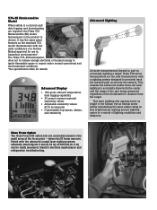
... Display • 100-point onboard temperature data logging capability • 30 preset common material emissivity values • Adjustable emissivity values (0.01 increments) • Customizable log names, alarms, and emissivity Advanced Sighting Accurate measurements depend in hazardous environments*. Paired with the extra confidence of the thermometer's distance from the target. Ideal for details. The Fluke 574...
... Display • 100-point onboard temperature data logging capability • 30 preset common material emissivity values • Adjustable emissivity values (0.01 increments) • Customizable log names, alarms, and emissivity Advanced Sighting Accurate measurements depend in hazardous environments*. Paired with the extra confidence of the thermometer's distance from the target. Ideal for details. The Fluke 574...
Fluke 572, 574, and 574-NI Infrared Thermometer Datasheet
Page 3
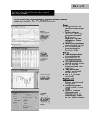
..., and record real-time temperature changes with the unit's data logging feature. The software provides a convenient way to export temperature data files in a format that can be used to error-proof inspection routes by graphing data accumulated with the software. The 574 can be used by programs such as text files for integration with Maintenance, Repair and Operations (MRO) systems and other database programs Software for...
..., and record real-time temperature changes with the unit's data logging feature. The software provides a convenient way to export temperature data files in a format that can be used to error-proof inspection routes by graphing data accumulated with the software. The 574 can be used by programs such as text files for integration with Maintenance, Repair and Operations (MRO) systems and other database programs Software for...
Fluke 572, 574, and 574-NI Infrared Thermometer Datasheet
Page 4
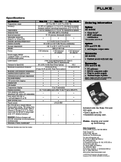
... Temperature display Display resolution Data graphing software (Windows® NT, 2000, XP compatible) Data output: RS-232 or 1 mV per degree (ºC or ºF) Hard carrying case Tripod mount The 574-NI has a factory Mutual Nonincendive rating. Fluke Corporation PO Box 9090, Everett, WA USA 98206 Fluke Europe B.V. Printed in ) with belt clip Accessories (574 and 574-NI) • PC software • RS232 computer cable • Plug-in power supply •...
... Temperature display Display resolution Data graphing software (Windows® NT, 2000, XP compatible) Data output: RS-232 or 1 mV per degree (ºC or ºF) Hard carrying case Tripod mount The 574-NI has a factory Mutual Nonincendive rating. Fluke Corporation PO Box 9090, Everett, WA USA 98206 Fluke Europe B.V. Printed in ) with belt clip Accessories (574 and 574-NI) • PC software • RS232 computer cable • Plug-in power supply •...

FE 574 Users Manual
Page 2
... nearest Fluke authorized service center to obtain return authorization information, then send the product to that Service Center with a description of purchase. NO OTHER WARRANTIES, SUCH AS FITNESS FOR A PARTICULAR PURPOSE, ARE EXPRESSED OR IMPLIED. 574 LIMITED WARRANTY AND LIMITATION OF LIABILITY This Fluke product will be free from defects...allow the exclusion or limitation of an implied warranty or of incidental or consequential damages, this limitation of operation or handling. This warranty does not cover fuses, disposable batteries, or damage from the date of the problem.
... nearest Fluke authorized service center to obtain return authorization information, then send the product to that Service Center with a description of purchase. NO OTHER WARRANTIES, SUCH AS FITNESS FOR A PARTICULAR PURPOSE, ARE EXPRESSED OR IMPLIED. 574 LIMITED WARRANTY AND LIMITATION OF LIABILITY This Fluke product will be free from defects...allow the exclusion or limitation of an implied warranty or of incidental or consequential damages, this limitation of operation or handling. This warranty does not cover fuses, disposable batteries, or damage from the date of the problem.
FE 574 Users Manual
Page 3
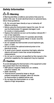
... or missing plastic. • Replace the batteries as soon as the battery indicator two or less segments. • Do not use the thermometer if it appears damaged. Do not use the thermometer if it operates abnormally. Caution To avoid damaging ...manual or the protection supplied by large or abrupt ambient temperature changes- 574 Safety Information Warning A Warning identifies conditions and actions that highly reflective objects will result in lower than actual temperature measurements. • Do not use in doubt, have the thermometer serviced. • Do not operate...
... or missing plastic. • Replace the batteries as soon as the battery indicator two or less segments. • Do not use the thermometer if it appears damaged. Do not use the thermometer if it operates abnormally. Caution To avoid damaging ...manual or the protection supplied by large or abrupt ambient temperature changes- 574 Safety Information Warning A Warning identifies conditions and actions that highly reflective objects will result in lower than actual temperature measurements. • Do not use in doubt, have the thermometer serviced. • Do not operate...

FE 574 Users Manual
Page 4
... Connections 18 Setup Alarm 19 Setup - Maximum and Minimum 16 Mode - Man. 574 Table of Contents Introduction 5 Warning for the Model 574 NI 6 Symbols and Safety Markings 7 Laser Warning and Serial Number Labels 8 Delivery Content 9 Functions and Display 10 Batteries and Measurement 11 Field of View 12 Spot Size 13 Emissivity - Range 24 Display - Explanation and Adjust 14 Emissivity - Table and Unknown Value 15 Mode - Time and Date 20 Setup...
... Connections 18 Setup Alarm 19 Setup - Maximum and Minimum 16 Mode - Man. 574 Table of Contents Introduction 5 Warning for the Model 574 NI 6 Symbols and Safety Markings 7 Laser Warning and Serial Number Labels 8 Delivery Content 9 Functions and Display 10 Batteries and Measurement 11 Field of View 12 Spot Size 13 Emissivity - Range 24 Display - Explanation and Adjust 14 Emissivity - Table and Unknown Value 15 Mode - Time and Date 20 Setup...
FE 574 Users Manual
Page 6
...Require Nonincendive Devices WARNING IN HAZARDOUS LOCATIONS DO NOT use other accessories, such as power supply and cables. The rating from this infrared thermometer has been tested to standards for the Model 574 NI Concerning Factory Mutual Approved Nonincendive Devices: Operation in Environments that this USA organization reads: "... ignite a specified flammable gas or vapor-in hazardous locations, use only Fluke temp probe part 2432508 and do not use serial port connections, change batteries or open serial port cover. or • adjacent to a Class I , Zone 2 IIC; To...
...Require Nonincendive Devices WARNING IN HAZARDOUS LOCATIONS DO NOT use other accessories, such as power supply and cables. The rating from this infrared thermometer has been tested to standards for the Model 574 NI Concerning Factory Mutual Approved Nonincendive Devices: Operation in Environments that this USA organization reads: "... ignite a specified flammable gas or vapor-in hazardous locations, use only Fluke temp probe part 2432508 and do not use serial port connections, change batteries or open serial port cover. or • adjacent to a Class I , Zone 2 IIC; To...

FE 574 Users Manual
Page 9
574 Delivery Content • The unit • Getting Started • Two AA batteries • Manual on CD • Thermocouple type K probe • Windows-based software on CD • RS232 cable • Power supply 9
574 Delivery Content • The unit • Getting Started • Two AA batteries • Manual on CD • Thermocouple type K probe • Windows-based software on CD • RS232 cable • Power supply 9

FE 574 Users Manual
Page 10
...Functions and Display FUNCTIONS USER INTERFACE Function keys and display: (A) Visual and audible A alarm (B) Display H B (C) Up and Down keys C (D) Enter G (E) Handle and battery compartment F D (DIP switches for adjustments are E inside handle) (F) Trigger (G) Tripod mount (H) 6 main function keys DISPLAY Displayed functions: (1) Laser condition / 1 2 Lock symbol (2) Time (or date) 9 3 (3) Main temperature display (4) Graphic display 8 (5) Emissivity value 4 5 (6) Status bar (7) Mode indicator 7 6 (8) Battery life indicator (9) MAX, MIN, DIF, AVG symbols...
...Functions and Display FUNCTIONS USER INTERFACE Function keys and display: (A) Visual and audible A alarm (B) Display H B (C) Up and Down keys C (D) Enter G (E) Handle and battery compartment F D (DIP switches for adjustments are E inside handle) (F) Trigger (G) Tripod mount (H) 6 main function keys DISPLAY Displayed functions: (1) Laser condition / 1 2 Lock symbol (2) Time (or date) 9 3 (3) Main temperature display (4) Graphic display 8 (5) Emissivity value 4 5 (6) Status bar (7) Mode indicator 7 6 (8) Battery life indicator (9) MAX, MIN, DIF, AVG symbols...
FE 574 Users Manual
Page 14
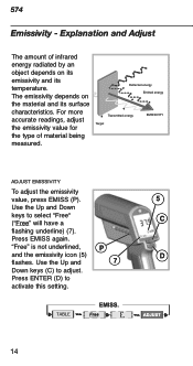
... keys (C) to activate this setting. 14 The emissivity depends on its emissivity and its surface characteristics. Press EMISS again. Explanation and Adjust The amount of material being measured. Reflected energy Emitted energy Transmitted energy Target EMISSIVITY EMISSIVITY ADJUST EMISSIVITY To adjust the emissivity value, press EMISS (P). 5 Use the Up and Down keys to select "Free" ("Free" will have a C flashing underline) (7). 574...
... keys (C) to activate this setting. 14 The emissivity depends on its emissivity and its surface characteristics. Press EMISS again. Explanation and Adjust The amount of material being measured. Reflected energy Emitted energy Transmitted energy Target EMISSIVITY EMISSIVITY ADJUST EMISSIVITY To adjust the emissivity value, press EMISS (P). 5 Use the Up and Down keys to select "Free" ("Free" will have a C flashing underline) (7). 574...
FE 574 Users Manual
Page 15
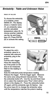
Press ENTER (D) to stabilize. Pull the unit's trigger. Pull the trigger again. Measure the same area using infrared measurement. UNKNOWN VALUE To adjust the unit's emissivity value for the reading to activate this setting. Wait for a material with unknown emissivity, plug in the display (7). Press the emissivity button (P). Use the Up and Down keys (C) to be shown in the probe. Place...
Press ENTER (D) to stabilize. Pull the unit's trigger. Pull the trigger again. Measure the same area using infrared measurement. UNKNOWN VALUE To adjust the unit's emissivity value for the reading to activate this setting. Wait for a material with unknown emissivity, plug in the display (7). Press the emissivity button (P). Use the Up and Down keys (C) to be shown in the probe. Place...

FE 574 Users Manual
Page 18
thermistor (11) TC - The real time infrared temperature is shown in the main display (3). 18 Press MODE, 3 until the desired probe symbol (7) appears. thermocouple (12) Thermocouple type J (13) Thermocouple type K 10 12 11 13 Connect the probe to the desired probe type. (10) NTC - The U7 probe temperature is shown in the lower part of 6 the display (6). 574 Probe Connections PROBE CONNECTIONS Open the battery compartment and set the switches ON or Off according to the input (U).
thermistor (11) TC - The real time infrared temperature is shown in the main display (3). 18 Press MODE, 3 until the desired probe symbol (7) appears. thermocouple (12) Thermocouple type J (13) Thermocouple type K 10 12 11 13 Connect the probe to the desired probe type. (10) NTC - The U7 probe temperature is shown in the lower part of 6 the display (6). 574 Probe Connections PROBE CONNECTIONS Open the battery compartment and set the switches ON or Off according to the input (U).
FE 574 Users Manual
Page 19
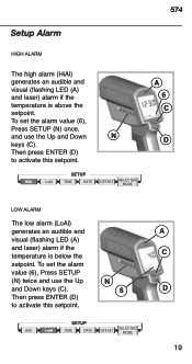
... Down N keys (C). To set the alarm value (6), Press SETUP (N) once, and use the Up N and Down keys (C). 6 D Then press ENTER (D) to activate this setpoint. 19 Then press ENTER (D) to activate this setpoint. 574 A 6 C D LOW ALARM The low alarm (LoAl) generates an audible and A visual (flashing LED (A) and laser) alarm if the temperature is above the setpoint. Setup Alarm HIGH ALARM The high alarm (HiAl) generates...
... Down N keys (C). To set the alarm value (6), Press SETUP (N) once, and use the Up N and Down keys (C). 6 D Then press ENTER (D) to activate this setpoint. 19 Then press ENTER (D) to activate this setpoint. 574 A 6 C D LOW ALARM The low alarm (LoAl) generates an audible and A visual (flashing LED (A) and laser) alarm if the temperature is above the setpoint. Setup Alarm HIGH ALARM The high alarm (HiAl) generates...
FE 574 Users Manual
Page 20
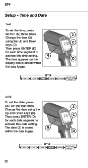
N The time appears on the D display and is stored N within the data logger. Then press ENTER (D) C for each date segment to activate this date setting. D 20 The date (2) is stored within the data logger. DATE To set the time, press SETUP (N) three times. 2 Change the time (2) using the Up and Down keys (C). 574 Setup - C Then press ENTER (D) for each time segment to activate this time setting. Time and Date TIME To set the date, press SETUP (N) four times. 2 Change the date using the Up and Down keys (C).
N The time appears on the D display and is stored N within the data logger. Then press ENTER (D) C for each date segment to activate this date setting. D 20 The date (2) is stored within the data logger. DATE To set the time, press SETUP (N) three times. 2 Change the time (2) using the Up and Down keys (C). 574 Setup - C Then press ENTER (D) for each time segment to activate this time setting. Time and Date TIME To set the date, press SETUP (N) four times. 2 Change the date using the Up and Down keys (C).
FE 574 Users Manual
Page 21
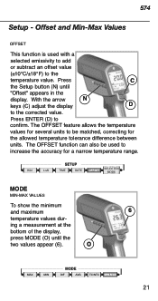
... (±10°C/±18°F) to be used to increase the accuracy for the allowed temperature tolerance difference between units. Press C the Setup button (N) until the two values appear (6). ing a measurement at the bottom of the display, press MODE (O) until "Offset" appears in the display. The OFFSET function can also be matched, correcting for a narrow temperature range.
... (±10°C/±18°F) to be used to increase the accuracy for the allowed temperature tolerance difference between units. Press C the Setup button (N) until the two values appear (6). ing a measurement at the bottom of the display, press MODE (O) until "Offset" appears in the display. The OFFSET function can also be matched, correcting for a narrow temperature range.
FE 574 Users Manual
Page 25
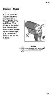
To select the interval time, use the Up and Down keys (C). Cycle CYCLE allows the adjustment of the display interval. The default value is shown at the status bar. Display - Press DISPLAY (L) until Cycl.: (7) is pre-set for L 0.2 sec. 574 7 C 25
To select the interval time, use the Up and Down keys (C). Cycle CYCLE allows the adjustment of the display interval. The default value is shown at the status bar. Display - Press DISPLAY (L) until Cycl.: (7) is pre-set for L 0.2 sec. 574 7 C 25
FE 574 Users Manual
Page 26
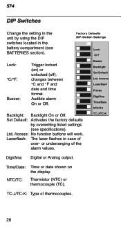
... time format. or underranging of thermocouples. 26 574 DIP Switches Change the setting in the unit by overwriting listed settings (see BATTERIES section). Buzzer: Audible alarm On or Off. Laserflash: The laser flashes in the battery compartment (see specifications). TC-J/TC-K: Type of the alarm values. TC-J/TC-K Digi/Ana: Digital or Analog output. Ltd. Access: No function buttons will work. Factory Defaults� DIP-Switch Settings� ON Lock C/ F Lock: Trigger locked (on the display. Set Default...
... time format. or underranging of thermocouples. 26 574 DIP Switches Change the setting in the unit by overwriting listed settings (see BATTERIES section). Buzzer: Audible alarm On or Off. Laserflash: The laser flashes in the battery compartment (see specifications). TC-J/TC-K: Type of the alarm values. TC-J/TC-K Digi/Ana: Digital or Analog output. Ltd. Access: No function buttons will work. Factory Defaults� DIP-Switch Settings� ON Lock C/ F Lock: Trigger locked (on the display. Set Default...

FE 574 Users Manual
Page 27
EEPROM-Err CalAreaErr ProbCalErr Battery icon flashes or LowBatt on Status line Blank display Laser won't work Problem Target temp. is over or under range EEPROM error Calibration errors Battery is low Action Select target within unit's specs Contact factory Contact factory Replace batteries Battery is dead Low or dead battery Ambient above 45°C (113°F) Replace batteries Replace batteries Operate unit in 45°C (113°F) ambient or below 27 574 Troubleshooting Code -O-U-
EEPROM-Err CalAreaErr ProbCalErr Battery icon flashes or LowBatt on Status line Blank display Laser won't work Problem Target temp. is over or under range EEPROM error Calibration errors Battery is low Action Select target within unit's specs Contact factory Contact factory Replace batteries Battery is dead Low or dead battery Ambient above 45°C (113°F) Replace batteries Replace batteries Operate unit in 45°C (113°F) ambient or below 27 574 Troubleshooting Code -O-U-

FE 574 Users Manual
Page 31
574 Specifications Temperature Range Display Resolution Accuracy (Infrared) Ambient derating Optical Resolution (Standard Focus) Optical Resolution (Close Focus) Accuracy (Thermocouple K & J) Accuracy (Thermistor) -30 to 0&#...;F) 1 mV/°C(°F) RS232 31 spot size at 0.98 feet) ± 2K or ± 0.75%, whichever is greater ± 0.6K ± 0.4K ± 1K ± 1.5K Repeatability (Infrared) Response Time (95%) Hot Spot Detection (30%) Spectral Range Ambient Operating Range Storage Temperature (without batteries) Analog output Digital Output ± 0.5% of reading or ±...
574 Specifications Temperature Range Display Resolution Accuracy (Infrared) Ambient derating Optical Resolution (Standard Focus) Optical Resolution (Close Focus) Accuracy (Thermocouple K & J) Accuracy (Thermistor) -30 to 0&#...;F) 1 mV/°C(°F) RS232 31 spot size at 0.98 feet) ± 2K or ± 0.75%, whichever is greater ± 0.6K ± 0.4K ± 1K ± 1.5K Repeatability (Infrared) Response Time (95%) Hot Spot Detection (30%) Spectral Range Ambient Operating Range Storage Temperature (without batteries) Analog output Digital Output ± 0.5% of reading or ±...

FE 574 Users Manual
Page 32
574 Power Battery Life Power supply (External) Dimensions Tripod Mount 2 x 1.5 V Alkaline Type AA 13 hrs. (50% laser and 50% backlight on) 7.5 V > 200 mA (Using the power supply the display automatically switches on) 200 x 170 x 50 mm (7.9 x 6.7 x 2 inches) 1/4"-20 UNC Factory Defaults Emissivity/Gain Emissivity Table Mode Hi Alarm Lo Alarm Offset Adjust Graphic Display Cycle Time Data logger Default 0.95 Free normal 50°C (100°F) 0°C (32°F) 0°C (0°F) Auto Range 0.2 sec Range 0.10 to...
574 Power Battery Life Power supply (External) Dimensions Tripod Mount 2 x 1.5 V Alkaline Type AA 13 hrs. (50% laser and 50% backlight on) 7.5 V > 200 mA (Using the power supply the display automatically switches on) 200 x 170 x 50 mm (7.9 x 6.7 x 2 inches) 1/4"-20 UNC Factory Defaults Emissivity/Gain Emissivity Table Mode Hi Alarm Lo Alarm Offset Adjust Graphic Display Cycle Time Data logger Default 0.95 Free normal 50°C (100°F) 0°C (32°F) 0°C (0°F) Auto Range 0.2 sec Range 0.10 to...


