
Fluke 287 and 289 Multimeter Users Manual
Page 2
...price. FLUKE SHALL ...years after Fluke discontinues manufacturing ...Fluke authorized service center to obtain...fluke.com. Fluke assumes no charge, replace or refund the purchase price of any non-warranty repair, Fluke...Fluke will pay return transportation for product repaired or replaced in material and workmanship for repair elsewhere. Fluke...Fluke authorized sales outlet and at no risk for damage in one country is not transferable. Fluke reserves the right to that service center, with a description of the DMM, Fluke...OR IMPLIED. Fluke Corporation P.O. P.O....ON FLUKE'S BEHALF. Fluke Europe ...
...price. FLUKE SHALL ...years after Fluke discontinues manufacturing ...Fluke authorized service center to obtain...fluke.com. Fluke assumes no charge, replace or refund the purchase price of any non-warranty repair, Fluke...Fluke will pay return transportation for product repaired or replaced in material and workmanship for repair elsewhere. Fluke...Fluke authorized sales outlet and at no risk for damage in one country is not transferable. Fluke reserves the right to that service center, with a description of the DMM, Fluke...OR IMPLIED. Fluke Corporation P.O. P.O....ON FLUKE'S BEHALF. Fluke Europe ...

Fluke 287 and 289 Multimeter Users Manual
Page 4
287/289 Users Manual Controlling Meter Power 12 Powering the Meter On and Off Manually 12 Battery Level Indicator 12 Automatic Power-Off 12 Battery Saver Mode 12 Controlling the Backlight 13 Selecting the Range ...13 Understanding Function Menus 13 Input Alert™ Feature...15 Using the Info Button ...15 ...
287/289 Users Manual Controlling Meter Power 12 Powering the Meter On and Off Manually 12 Battery Level Indicator 12 Automatic Power-Off 12 Battery Saver Mode 12 Controlling the Backlight 13 Selecting the Range ...13 Understanding Function Menus 13 Input Alert™ Feature...15 Using the Info Button ...15 ...

Fluke 287 and 289 Multimeter Users Manual
Page 6
287/289 Users Manual Error Messages ...56 Maintenance ...57 General Maintenance 57 Testing the Fuses...57 Replacing the Batteries 59 Replacing the Fuses 59 Test Lead Storage...59 In Case of Difficulty ...61 Service and Parts ...62 General Specifications 66 Detailed Specifications 67 AC ...
287/289 Users Manual Error Messages ...56 Maintenance ...57 General Maintenance 57 Testing the Fuses...57 Replacing the Batteries 59 Replacing the Fuses 59 Test Lead Storage...59 In Case of Difficulty ...61 Service and Parts ...62 General Specifications 66 Detailed Specifications 67 AC ...

Fluke 287 and 289 Multimeter Users Manual
Page 10
Diode Testing...37 21. Functions Allowing Frequency Measurement 42 24. Current Measurement Setup 40 22. Duty Cycle Measurements ...44 26. Duty Cycle Display ...45 27. Capacitance Measurement 35 20. Frequency Display ...43 25. Replaceable Parts...64 viii Replacing Batteries and Fuses 60 31. Current Measurement Circuit Connection 41 23. Test Lead Storage ...59 30. 287/289 Users Manual 18. Pulse Width Measurements 46 28. Testing the Current Fuses...58 29. Conductance Measurement 34 19.
Diode Testing...37 21. Functions Allowing Frequency Measurement 42 24. Current Measurement Setup 40 22. Duty Cycle Measurements ...44 26. Duty Cycle Display ...45 27. Capacitance Measurement 35 20. Frequency Display ...43 25. Replaceable Parts...64 viii Replacing Batteries and Fuses 60 31. Current Measurement Circuit Connection 41 23. Test Lead Storage ...59 30. 287/289 Users Manual 18. Pulse Width Measurements 46 28. Testing the Current Fuses...58 29. Conductance Measurement 34 19.

Fluke 287 and 289 Multimeter Users Manual
Page 12
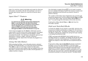
... Do not use the Low Pass Filter option to detect the possible presence of hazardous voltages. Replace damaged test leads before opening the battery door. • Inspect the test leads for damaged insulation or exposed metal. First, make a voltage measurement without the filter to ...verify the presence of hazardous voltage. 287/289 Users Manual • Make sure the battery door is indicated may be present. Check the test leads for measurements. • Avoid working with the circuit. 2...
... Do not use the Low Pass Filter option to detect the possible presence of hazardous voltages. Replace damaged test leads before opening the battery door. • Inspect the test leads for damaged insulation or exposed metal. First, make a voltage measurement without the filter to ...verify the presence of hazardous voltage. 287/289 Users Manual • Make sure the battery door is indicated may be present. Check the test leads for measurements. • Avoid working with the circuit. 2...
Fluke 287 and 289 Multimeter Users Manual
Page 13
True-rms Digital Multimeters Hazardous Voltage • Do not remove batteries while the Meter is turned on or a signal is applied to the Meter's input jacks. • Before measuring current, check the Meter's fuses. (See "Testing ...
True-rms Digital Multimeters Hazardous Voltage • Do not remove batteries while the Meter is turned on or a signal is applied to the Meter's input jacks. • Before measuring current, check the Meter's fuses. (See "Testing ...
Fluke 287 and 289 Multimeter Users Manual
Page 14
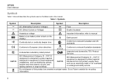
...voltage W Important Information; N10140 Conforms to relevant Canadian and US standards Conforms to protect against transients in equipment in large buildings. 287/289 Users Manual Symbols Table 1 lists and describes the symbols used on the display) J Earth ground Continuity test or continuity ...beeper tone Conforms to European Union directives $ ; CAT IV IEC Measurement Category IV - Table 1. Go to manual Battery (Low battery when shown on the Meter and in this product as distribution panels, feeders and short branch circuits, and lighting systems in ...
...voltage W Important Information; N10140 Conforms to relevant Canadian and US standards Conforms to protect against transients in equipment in large buildings. 287/289 Users Manual Symbols Table 1 lists and describes the symbols used on the display) J Earth ground Continuity test or continuity ...beeper tone Conforms to European Union directives $ ; CAT IV IEC Measurement Category IV - Table 1. Go to manual Battery (Low battery when shown on the Meter and in this product as distribution panels, feeders and short branch circuits, and lighting systems in ...
Fluke 287 and 289 Multimeter Users Manual
Page 17
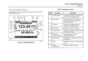
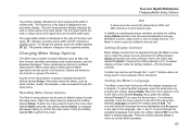
...). Indicates a negative reading. Understanding the Display Display features shown in Figure 2 are described in the internal clock. Analog display of the six AA batteries. Indicates hazardous voltage present at the Meter's input. Indicates the time set in Table 3 and the following sections. 7 8 9 10 11 12... Save 1 Setup Figure 2. Display Features Item Function A Softkey labels B Bar graph C Relative D Minus sign E Lightning bolt F Remote communication G Battery level H Time I Mode annunciators Indication Indicates the function of the button just below the displayed label.
...). Indicates a negative reading. Understanding the Display Display features shown in Figure 2 are described in the internal clock. Analog display of the six AA batteries. Indicates hazardous voltage present at the Meter's input. Indicates the time set in Table 3 and the following sections. 7 8 9 10 11 12... Save 1 Setup Figure 2. Display Features Item Function A Softkey labels B Bar graph C Relative D Minus sign E Lightning bolt F Remote communication G Battery level H Time I Mode annunciators Indication Indicates the function of the button just below the displayed label.

Fluke 287 and 289 Multimeter Users Manual
Page 18
...like Crest Factor. For frequency, duty cycle, pulse width, dBm, and crest factor functions, the bar graph represents the amplitude of the selected range. 287/289 Users Manual Table 3. K Date Indicates the date set in the primary display. The bar graph is displayed. For dc voltage, dc current, ...and all relative percent modes, a zero-centered bar graph is not shown for battery level, time of the normal bar graph. In the 50 Vac range, for positive off -scale values, f appears to the full-scale value ...
...like Crest Factor. For frequency, duty cycle, pulse width, dBm, and crest factor functions, the bar graph represents the amplitude of the selected range. 287/289 Users Manual Table 3. K Date Indicates the date set in the primary display. The bar graph is displayed. For dc voltage, dc current, ...and all relative percent modes, a zero-centered bar graph is not shown for battery level, time of the normal bar graph. In the 50 Vac range, for positive off -scale values, f appears to the full-scale value ...
Fluke 287 and 289 Multimeter Users Manual
Page 22
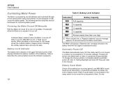
...or completely disable automatic power-off is turned off , press O to help conserve battery power. Note Collected data is retained when the Meter is enabled (set period of the batteries. 287/289 Users Manual Controlling Meter Power The Meter is not moved for controlling Meter power.... Battery Level Indicator The battery level indicator in record, MIN MAX record, or Peak record modes. Pressing...
...or completely disable automatic power-off is turned off , press O to help conserve battery power. Note Collected data is retained when the Meter is enabled (set period of the batteries. 287/289 Users Manual Controlling Meter Power The Meter is not moved for controlling Meter power.... Battery Level Indicator The battery level indicator in record, MIN MAX record, or Peak record modes. Pressing...

Fluke 287 and 289 Multimeter Users Manual
Page 23
... off. Each additional press of operation. recording mode, the time period is 5 minutes. The Meter displays a message if the battery level will continue to flash to display the highest available precision (resolution) for the selected function, including the display. Understanding Function Menus...the next higher range, unless it is enabled, press R to the lowest range. Battery saver mode conserves battery power by pressing the softkey labeled Menu (F1). The Meter "wakes up" from battery-save mode under the following conditions: • A button is pressed • The...
... off. Each additional press of operation. recording mode, the time period is 5 minutes. The Meter displays a message if the battery level will continue to flash to display the highest available precision (resolution) for the selected function, including the display. Understanding Function Menus...the next higher range, unless it is enabled, press R to the lowest range. Battery saver mode conserves battery power by pressing the softkey labeled Menu (F1). The Meter "wakes up" from battery-save mode under the following conditions: • A button is pressed • The...
Fluke 287 and 289 Multimeter Users Manual
Page 25
... display and hazardous voltage icon (z) continue to reveal the off -screen menu items. Conversely, with ) a powered circuit when a lead is plugged into a current terminal. The battery level indicator is detected.
... display and hazardous voltage icon (z) continue to reveal the off -screen menu items. Conversely, with ) a powered circuit when a lead is plugged into a current terminal. The battery level indicator is detected.

Fluke 287 and 289 Multimeter Users Manual
Page 27
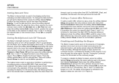
...respective elapsed times. MIN MAX Record Display est42.eps To stop a MIN MAX recording session, press M or the softkey labeled Stop. To extend battery life during MIN MAX recording, the Meter will cause all the accumulated data to be lost. The summary information in Figure 6, the Meter displays...maximum, average, and minimum values appear in this manual. As shown in the display freezes, and the softkeys change rapidly, turn on the battery saver mode. Pressing M again or the softkey labeled Close exits the MIN MAX record session without saving the collected data. Next, press the ...
...respective elapsed times. MIN MAX Record Display est42.eps To stop a MIN MAX recording session, press M or the softkey labeled Stop. To extend battery life during MIN MAX recording, the Meter will cause all the accumulated data to be lost. The summary information in Figure 6, the Meter displays...maximum, average, and minimum values appear in this manual. As shown in the display freezes, and the softkeys change rapidly, turn on the battery saver mode. Pressing M again or the softkey labeled Close exits the MIN MAX record session without saving the collected data. Next, press the ...

Fluke 287 and 289 Multimeter Users Manual
Page 29
... stops the session, discards all the accumulated data to store the Peak screen data. To extend battery life during peak record, the Meter enters a battery-saver mode after a period of time set for more information on the battery saver mode. See the "Setting Backlight and Auto Off Timeouts" section for the Auto Off...
... stops the session, discards all the accumulated data to store the Peak screen data. To extend battery life during peak record, the Meter enters a battery-saver mode after a period of time set for more information on the battery saver mode. See the "Setting Backlight and Auto Off Timeouts" section for the Auto Off...
Fluke 287 and 289 Multimeter Users Manual
Page 57
... available languages, then press the softkey labeled OK to the opposite polarity. Move the menu selector next to as date and time formats, backlight and battery save mode timeouts, and the displayed language. These variables are referred to the menu item labeled Display. Information about the Meter, such as well. A message...
... available languages, then press the softkey labeled OK to the opposite polarity. Move the menu selector next to as date and time formats, backlight and battery save mode timeouts, and the displayed language. These variables are referred to the menu item labeled Display. Information about the Meter, such as well. A message...
Fluke 287 and 289 Multimeter Users Manual
Page 58
...labeled Date/Time to the menu item labeled Instrument. With the desired reference displayed, press the softkey labeled OK to add this setup option. The battery-saver mode powers down circuits that function is indicated in the display's status bar (see item 12 in Figure 2). Next press the softkey labeled... return to the menu item labeled Display. To change the selected date or time element value. Use 7 and 8 to a value other than Off. 287/289 Users Manual Setting Date and Time The Meter's internal clock is used in the display and for MIN MAX and Peak recording. Position the...
...labeled Date/Time to the menu item labeled Instrument. With the desired reference displayed, press the softkey labeled OK to add this setup option. The battery-saver mode powers down circuits that function is indicated in the display's status bar (see item 12 in Figure 2). Next press the softkey labeled... return to the menu item labeled Display. To change the selected date or time element value. Use 7 and 8 to a value other than Off. 287/289 Users Manual Setting Date and Time The Meter's internal clock is used in the display and for MIN MAX and Peak recording. Position the...

Fluke 287 and 289 Multimeter Users Manual
Page 64
...Viewing Trend Data" section), or close the recording session. After stopping a recording session, choose to scroll through the event threshold 54 values. 287/289 Users Manual The Meter allocates memory in the display and the green LED surrounding the power button (O) flashes. Note The maximum number of...move the menu selector next to the menu item labeled Recording and press the softkey labeled Recording to access the setup menu. If the battery level is anything but the event counter continues to advance to indicate this point, events are set, press the softkey labeled Start, ...
...Viewing Trend Data" section), or close the recording session. After stopping a recording session, choose to scroll through the event threshold 54 values. 287/289 Users Manual The Meter allocates memory in the display and the green LED surrounding the power button (O) flashes. Note The maximum number of...move the menu selector next to the menu item labeled Recording and press the softkey labeled Recording to access the setup menu. If the battery level is anything but the event counter continues to advance to indicate this point, events are set, press the softkey labeled Start, ...
Fluke 287 and 289 Multimeter Users Manual
Page 66
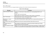
.... Not enough memory for operation. Table 10. Error: Date and Time need to measure current but rotary switch not in corresponding A/mA or μA position. 287/289 Users Manual Error Messages Table 10 list some of the error messages the Meter may display and the conditions that may be... Batteries were left out too long and the Meter's date and time were lost. Lead in A or mA/μA jack but no lead in both A and ...
.... Not enough memory for operation. Table 10. Error: Date and Time need to measure current but rotary switch not in corresponding A/mA or μA position. 287/289 Users Manual Error Messages Table 10 list some of the error messages the Meter may display and the conditions that may be... Batteries were left out too long and the Meter's date and time were lost. Lead in A or mA/μA jack but no lead in both A and ...
Fluke 287 and 289 Multimeter Users Manual
Page 67
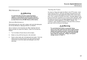
...05 kΩ for the € jack. Shake out any input signals before replacing the battery or fuses. The resistance value should be in the terminals can affect readings and can ... 3. Soak a clean swab with the amperage, voltage, and speed ratings shown in the 287/289 Service Information. True-rms Digital Multimeters Maintenance Testing the Fuses As shown in the S... only by qualified personnel as follows: 1. To prevent damage or injury, install only Fluke specified replacement fuses with mild detergent and water. Dry each terminal. General Maintenance Periodically...
...05 kΩ for the € jack. Shake out any input signals before replacing the battery or fuses. The resistance value should be in the terminals can affect readings and can ... 3. Soak a clean swab with the amperage, voltage, and speed ratings shown in the 287/289 Service Information. True-rms Digital Multimeters Maintenance Testing the Fuses As shown in the S... only by qualified personnel as follows: 1. To prevent damage or injury, install only Fluke specified replacement fuses with mild detergent and water. Dry each terminal. General Maintenance Periodically...

Fluke 287 and 289 Multimeter Users Manual
Page 69
... the proper method for storing the test leads with the amperage, voltage, and interrupt ratings shown in Table 11. 5. Remove the battery door assembly by turning the screw one -half turn counterclockwise. 3. Replacing the Fuses Referring to Figure 30, examine or replace the ...test leads from the terminals. 2. Reinstall the battery door assembly and secure it by gently prying one -half turn clockwise. Observe proper polarity. 4. Install only Fluke specified replacement fuses with the Meter. Replace the batteries with 1.5 volt AA batteries (NEDA 15A IEC LR6). Turn the Meter off...
... the proper method for storing the test leads with the amperage, voltage, and interrupt ratings shown in Table 11. 5. Remove the battery door assembly by turning the screw one -half turn counterclockwise. 3. Replacing the Fuses Referring to Figure 30, examine or replace the ...test leads from the terminals. 2. Reinstall the battery door assembly and secure it by gently prying one -half turn clockwise. Observe proper polarity. 4. Install only Fluke specified replacement fuses with the Meter. Replace the batteries with 1.5 volt AA batteries (NEDA 15A IEC LR6). Turn the Meter off...


