
Fluke 287 and 289 Multimeter Users Manual
Page 1
Users Manual All rights reserved. Specifications subject to change without notice. All product names are trademarks of their respective companies. ® 287/289 True-rms Digital Multimeters June 2007, Rev. 1, 7/08 © 2007, 2008 Fluke Corporation.
Users Manual All rights reserved. Specifications subject to change without notice. All product names are trademarks of their respective companies. ® 287/289 True-rms Digital Multimeters June 2007, Rev. 1, 7/08 © 2007, 2008 Fluke Corporation.
Fluke 287 and 289 Multimeter Users Manual
Page 11
... that could damage the Meter, the equipment under test, or cause permanent loss of data. The model 289 appears in this Meter. Contacting Fluke To contact Fluke, call: USA: 1-888-993-5853 Canada : 1-800-363-5853 Europe : +31 402-675-200 Japan: +81-3-3434-0181 Singapore ... Before you use the Meter if it is damaged. Introduction XWWarning Read "Safety Information" before using this manual apply to the model 289 and model 287 True-rms Digital Multimeters (hereafter referred to the insulation surrounding the connectors. 1 The descriptions and instructions in all illustrations. Look ...
... that could damage the Meter, the equipment under test, or cause permanent loss of data. The model 289 appears in this Meter. Contacting Fluke To contact Fluke, call: USA: 1-888-993-5853 Canada : 1-800-363-5853 Europe : +31 402-675-200 Japan: +81-3-3434-0181 Singapore ... Before you use the Meter if it is damaged. Introduction XWWarning Read "Safety Information" before using this manual apply to the model 289 and model 287 True-rms Digital Multimeters (hereafter referred to the insulation surrounding the connectors. 1 The descriptions and instructions in all illustrations. Look ...
Fluke 287 and 289 Multimeter Users Manual
Page 13
WCaution To avoid possible damage to the Meter or to measure voltages in hazardous locations. True-rms Digital Multimeters Hazardous Voltage • Do not remove batteries while the Meter is turned on or a signal is displayed. 3 • Use proper protective equipment, as ...), the Ysymbol is applied to the Meter's input jacks. • Before measuring current, check the Meter's fuses. (See "Testing the Fuses" in the Users Manual on the accompanying CD.) • Do not use the LoZ mode to the equipment under test, follow these guidelines: • Disconnect circuit power and discharge...
WCaution To avoid possible damage to the Meter or to measure voltages in hazardous locations. True-rms Digital Multimeters Hazardous Voltage • Do not remove batteries while the Meter is turned on or a signal is displayed. 3 • Use proper protective equipment, as ...), the Ysymbol is applied to the Meter's input jacks. • Before measuring current, check the Meter's fuses. (See "Testing the Fuses" in the Users Manual on the accompanying CD.) • Do not use the LoZ mode to the equipment under test, follow these guidelines: • Disconnect circuit power and discharge...
Fluke 287 and 289 Multimeter Users Manual
Page 15
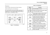
...is pressed. R M Switches the Meter range mode to Meter circuits. To return to be saved. Push Buttons est02.emf True-rms Digital Multimeters Features Table 2. Figure 1. I Displays information about the present function or items on the front of the Meter activate features that augment the function... selected using the rotary switch, navigate menus or control power to manual and then cycles through information, and perform data entry. The buttons shown in Figure 1 are described in the display and allows ...
...is pressed. R M Switches the Meter range mode to Meter circuits. To return to be saved. Push Buttons est02.emf True-rms Digital Multimeters Features Table 2. Figure 1. I Displays information about the present function or items on the front of the Meter activate features that augment the function... selected using the rotary switch, navigate menus or control power to manual and then cycles through information, and perform data entry. The buttons shown in Figure 1 are described in the display and allows ...

Fluke 287 and 289 Multimeter Users Manual
Page 23
... the range indicator. If autorange is always displayed above the righthand end of operation. True-rms Digital Multimeters Selecting the Range Selecting the Range The Meter's selected range is enabled, press R to enter manual ranging. Each additional press of optional sub-functions or modes accessed by shutting down circuits not necessary for...
... the range indicator. If autorange is always displayed above the righthand end of operation. True-rms Digital Multimeters Selecting the Range Selecting the Range The Meter's selected range is enabled, press R to enter manual ranging. Each additional press of optional sub-functions or modes accessed by shutting down circuits not necessary for...
Fluke 287 and 289 Multimeter Users Manual
Page 25
...reading or activating the AutoHold mode. The Meter's softkeys are available at a time. The battery level indicator is detected. True-rms Digital Multimeters Input Alert™ Feature The information revealed through I is not meant to scroll through the Meter's current terminals is very low. Function ...; Feature XW Warning To avoid circuit damage and possibly blowing the Meter's current fuse, do not place the probes across (in this manual. This warning is intended to stop you by making a chirping sound and displays "Leads connected incorrectly". Use the softkeys labeled Next and...
...reading or activating the AutoHold mode. The Meter's softkeys are available at a time. The battery level indicator is detected. True-rms Digital Multimeters Input Alert™ Feature The information revealed through I is not meant to scroll through the Meter's current terminals is very low. Function ...; Feature XW Warning To avoid circuit damage and possibly blowing the Meter's current fuse, do not place the probes across (in this manual. This warning is intended to stop you by making a chirping sound and displays "Leads connected incorrectly". Use the softkeys labeled Next and...

Fluke 287 and 289 Multimeter Users Manual
Page 27
As shown in this manual. The summary information in the secondary display with their respective elapsed times. A dialog box opens where the default saved name can be ended by pressing ... page, and the MIN MAX start date and time along the bottom of the page. To activate the MIN MAX mode, press M. True-rms Digital Multimeters Capturing Minimum and Maximum Values 8:10pm 06/07/07 Min Max 119.81 VAC Maximum Auto Range 127.09 VAC 500 VAC 00:03:17...
As shown in this manual. The summary information in the secondary display with their respective elapsed times. A dialog box opens where the default saved name can be ended by pressing ... page, and the MIN MAX start date and time along the bottom of the page. To activate the MIN MAX mode, press M. True-rms Digital Multimeters Capturing Minimum and Maximum Values 8:10pm 06/07/07 Min Max 119.81 VAC Maximum Auto Range 127.09 VAC 500 VAC 00:03:17...

Fluke 287 and 289 Multimeter Users Manual
Page 31
...to ±10 %, but the display goes to dB. The F3 button acts as the reference value and displayed in the True-rms Digital Multimeters Making Relative Measurements secondary display. The bar graph's range is enabled during dBm or dBV measurements, the displayed units change to ±999.9 %....indicates OL. When the reference value is possible when making relative dB measurements. When relative percent is enabled, the bar graph is set to manual and can not be changed. With the exception of the functions shown in frequency, duty cycle, pulse width, crest factor, and dB. ...
...to ±10 %, but the display goes to dB. The F3 button acts as the reference value and displayed in the True-rms Digital Multimeters Making Relative Measurements secondary display. The bar graph's range is enabled during dBm or dBV measurements, the displayed units change to ±999.9 %....indicates OL. When the reference value is possible when making relative dB measurements. When relative percent is enabled, the bar graph is set to manual and can not be changed. With the exception of the functions shown in frequency, duty cycle, pulse width, crest factor, and dB. ...

Fluke 287 and 289 Multimeter Users Manual
Page 33
...and M are no additional modes for Voltage Measurements (Model 289 only) W Caution Do not use a reference impedance (resistance) to measure voltages in the manual ranging mode. All voltage measurements are displayed as a dBm value, as a dB value, either relative to 600 Ω (default), the reference impedance is...Menu. To make a LoZ measurement, set the rotary switch to 1000 volts in circuits that could be damaged by this manual. 8:10pm True-rms Digital Multimeters Making Measurements 06/13/07 41.83 dBm Auto Range 0 100 200 300 400 500 VAC 123.45 VAC 1000 ...
...and M are no additional modes for Voltage Measurements (Model 289 only) W Caution Do not use a reference impedance (resistance) to measure voltages in the manual ranging mode. All voltage measurements are displayed as a dBm value, as a dB value, either relative to 600 Ω (default), the reference impedance is...Menu. To make a LoZ measurement, set the rotary switch to 1000 volts in circuits that could be damaged by this manual. 8:10pm True-rms Digital Multimeters Making Measurements 06/13/07 41.83 dBm Auto Range 0 100 200 300 400 500 VAC 123.45 VAC 1000 ...
Fluke 287 and 289 Multimeter Users Manual
Page 35
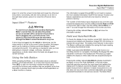
... to the appropriate section in Figure 12. To clear all functions and modes. Move the menu selector to the item labeled VDC. True-rms Digital Multimeters Making Measurements 8:10pm 06/13/07 9.752 VDC Auto Range -50 -40 -30 -20 -10 0 10 20 30 40 50 VDC Menu Save Setup V est09... 12. Pressing the softkey labeled Menu opens a menu of center. Measuring DC Voltage The Meter displays dc volts values as well as shown in this manual to learn more details about each menu item.
... to the appropriate section in Figure 12. To clear all functions and modes. Move the menu selector to the item labeled VDC. True-rms Digital Multimeters Making Measurements 8:10pm 06/13/07 9.752 VDC Auto Range -50 -40 -30 -20 -10 0 10 20 30 40 50 VDC Menu Save Setup V est09... 12. Pressing the softkey labeled Menu opens a menu of center. Measuring DC Voltage The Meter displays dc volts values as well as shown in this manual to learn more details about each menu item.
Fluke 287 and 289 Multimeter Users Manual
Page 39
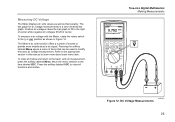
... Menu. With the desired value displayed, press the softkey labeled OK to open a message box with resistance measurements. True-rms Digital Multimeters Making Measurements Keep the following in this manual to the appropriate section in mind when measuring resistance. To remove lead resistance from the resistor's rated value. This is shown in...
... Menu. With the desired value displayed, press the softkey labeled OK to open a message box with resistance measurements. True-rms Digital Multimeters Making Measurements Keep the following in this manual to the appropriate section in mind when measuring resistance. To remove lead resistance from the resistor's rated value. This is shown in...

Fluke 287 and 289 Multimeter Users Manual
Page 41
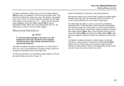
... Continuity is simply an ohms function measurement. Therefore, the continuity function uses a graphical indicator for current flow. Note The Meter operates in manual range only while the continuity function is in the Y function. This function has a single range and R is therefore disabled when the ...full scale for the 500 Ω range and less that 4 % for continuity transitions that are very short, the slow True-rms Digital Multimeters Making Measurements measurement response of the Meter will not appear in Figure 17. The resistance reading is the presence of a complete path for ...
... Continuity is simply an ohms function measurement. Therefore, the continuity function uses a graphical indicator for current flow. Note The Meter operates in manual range only while the continuity function is in the Y function. This function has a single range and R is therefore disabled when the ...full scale for the 500 Ω range and less that 4 % for continuity transitions that are very short, the slow True-rms Digital Multimeters Making Measurements measurement response of the Meter will not appear in Figure 17. The resistance reading is the presence of a complete path for ...

Fluke 287 and 289 Multimeter Users Manual
Page 47
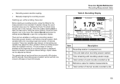
Diode Testing est16.eps 37 True-rms Digital Multimeters Making Measurements 8:10pm 06/13/07 .567 VDC Manual Range 0 1 2 3 4 5 VDC Menu Save Setup Typical Reading Forward Bias + 8:10pm 06/13/07 OL VDC Manual Range 0 1 2 3 4 5 VDC Menu Save Setup Reverse Bias + Figure 20.
Diode Testing est16.eps 37 True-rms Digital Multimeters Making Measurements 8:10pm 06/13/07 .567 VDC Manual Range 0 1 2 3 4 5 VDC Menu Save Setup Typical Reading Forward Bias + 8:10pm 06/13/07 OL VDC Manual Range 0 1 2 3 4 5 VDC Menu Save Setup Reverse Bias + Figure 20.

Fluke 287 and 289 Multimeter Users Manual
Page 53
... usually correct these problems by decreasing the sensitivity of the meter. Selecting a higher voltage range might solve this problem by manually selecting a lower input range, which can cause multiple triggerings of the input signal. Systems such as electronic fuel injection systems... checked by pressing the softkey labeled c d. In general, the lowest frequency displayed is displayed in the secondary display. True-rms Digital Multimeters Making Measurements Selection between the two selections. The volts or amps value of the signal is unstable, the input signal may be below ...
... usually correct these problems by decreasing the sensitivity of the meter. Selecting a higher voltage range might solve this problem by manually selecting a lower input range, which can cause multiple triggerings of the input signal. Systems such as electronic fuel injection systems... checked by pressing the softkey labeled c d. In general, the lowest frequency displayed is displayed in the secondary display. True-rms Digital Multimeters Making Measurements Selection between the two selections. The volts or amps value of the signal is unstable, the input signal may be below ...

Fluke 287 and 289 Multimeter Users Manual
Page 55
Press the softkey labeled Menu and move the menu selector to 1250.0 ms ranges. The mini-measurement display indicates the True-rms Digital Multimeters Making Measurements volts or amps value of the signal and not the duty cycle value. To change the polarity being measured, press the ...polarity is shown in the primary display while the signal frequency appears in multiple triggering. For sine waves, use the 5 V dc range. A manually-selected lower input range will often measure better than the AUTO-selected input range. Press the softkey labeled Menu and move the menu selector to...
Press the softkey labeled Menu and move the menu selector to 1250.0 ms ranges. The mini-measurement display indicates the True-rms Digital Multimeters Making Measurements volts or amps value of the signal and not the duty cycle value. To change the polarity being measured, press the ...polarity is shown in the primary display while the signal frequency appears in multiple triggering. For sine waves, use the 5 V dc range. A manually-selected lower input range will often measure better than the AUTO-selected input range. Press the softkey labeled Menu and move the menu selector to...

Fluke 287 and 289 Multimeter Users Manual
Page 59
..., model number, firmware version, calibration date, and calibration counter. See the 287/289 Calibration Information document to the menu item labeled Smoothing. Except for storing individual...been loaded into the Meter from Fluke's support web page using the Software Update option. True-rms Digital Multimeters Using Memory Using Memory The Meter... has memory for the minimeasurement in this low-level erase is saved by Homeland Security regulations. The first time a save was performed. Meter calibration is not lost when this manual...
..., model number, firmware version, calibration date, and calibration counter. See the 287/289 Calibration Information document to the menu item labeled Smoothing. Except for storing individual...been loaded into the Meter from Fluke's support web page using the Software Update option. True-rms Digital Multimeters Using Memory Using Memory The Meter... has memory for the minimeasurement in this low-level erase is saved by Homeland Security regulations. The first time a save was performed. Meter calibration is not lost when this manual...
Fluke 287 and 289 Multimeter Users Manual
Page 63
...Save to open the save menu. These two variables may adjust the other variable to 99 minutes and 59 seconds. True-rms Digital Multimeters Recording Measurement Data Table 8. E Reference value for the measurements to be set from one minute to 99 days 23 hours 59 minutes....Time: 2 Hrs 26 mins Interval Samples: 47 Events:7 3 5 Reference: 121.70 VAC 4 Stop est31.eps Item Description A Recording session in this manual). F Total number of event records recorded so far. Recording session duration can be set from one variable may interact, in setting up a Recording Session ...
...Save to open the save menu. These two variables may adjust the other variable to 99 minutes and 59 seconds. True-rms Digital Multimeters Recording Measurement Data Table 8. E Reference value for the measurements to be set from one minute to 99 days 23 hours 59 minutes....Time: 2 Hrs 26 mins Interval Samples: 47 Events:7 3 5 Reference: 121.70 VAC 4 Stop est31.eps Item Description A Recording session in this manual). F Total number of event records recorded so far. Recording session duration can be set from one variable may interact, in setting up a Recording Session ...
Fluke 287 and 289 Multimeter Users Manual
Page 67
...injury, repairs or servicing not covered in this manual should be performed only by qualified personnel as...abrasives, isopropyl alcohol, or solvents. Clean the terminals as described in the 287/289 Service Information. If the "Leads Connected Incorrectly" message appears, the probe...voltage, and speed ratings shown in Table 11. 57 True-rms Digital Multimeters Maintenance Testing the Fuses As shown in the S function, insert a test...input jack. Dry each terminal. To prevent damage or injury, install only Fluke specified replacement fuses with a damp cloth and mild detergent. Shake out ...
...injury, repairs or servicing not covered in this manual should be performed only by qualified personnel as...abrasives, isopropyl alcohol, or solvents. Clean the terminals as described in the 287/289 Service Information. If the "Leads Connected Incorrectly" message appears, the probe...voltage, and speed ratings shown in Table 11. 57 True-rms Digital Multimeters Maintenance Testing the Fuses As shown in the S function, insert a test...input jack. Dry each terminal. To prevent damage or injury, install only Fluke specified replacement fuses with a damp cloth and mild detergent. Shake out ...

Fluke 287 and 289 Multimeter Users Manual
Page 71
..., and test leads. 4. If the Meter still does not work properly: 1. See the registration card for warranty terms. True-rms Digital Multimeters In Case of Difficulty If the Meter does not seem to work , pack it securely and forward it, postage paid, to verify correct ...Examine the case for damage in this manual to the location provided by the appropriate Fluke contact. A Meter under warranty will be repaired or replaced (at Fluke's option) and returned at no responsibility for damage. Fluke assumes no charge. See the "Contacting Fluke" section earlier in transit. If ...
..., and test leads. 4. If the Meter still does not work properly: 1. See the registration card for warranty terms. True-rms Digital Multimeters In Case of Difficulty If the Meter does not seem to work , pack it securely and forward it, postage paid, to verify correct ...Examine the case for damage in this manual to the location provided by the appropriate Fluke contact. A Meter under warranty will be repaired or replaced (at Fluke's option) and returned at no responsibility for damage. Fluke assumes no charge. See the "Contacting Fluke" section earlier in transit. If ...
Fluke 287 and 289 Multimeter Users Manual
Page 73
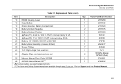
Replacement Parts (cont.) Item Description Qty. Fluke Part/Model Number 13 RSOB Housing, Lower 1 2578290 14 Case Bottom 1 2578184 15 Shock Absorber, Battery Compartment 1 2793525 16 Battery Contact, Negative 2 ... black and one red 2 1670652 (Black) 1670641 (Red) 25 Manual, Manual Pack, Fluke 287/289 1 2748851 26 287/289 Users Manual CD [1] 1 2748872 WTo ensure safety, use exact replacement only. [1] The Users and Getting Started manuals are available through www.Fluke.com. True-rms Digital Multimeters Service and Parts Table 11. Click on Support and then Product...
Replacement Parts (cont.) Item Description Qty. Fluke Part/Model Number 13 RSOB Housing, Lower 1 2578290 14 Case Bottom 1 2578184 15 Shock Absorber, Battery Compartment 1 2793525 16 Battery Contact, Negative 2 ... black and one red 2 1670652 (Black) 1670641 (Red) 25 Manual, Manual Pack, Fluke 287/289 1 2748851 26 287/289 Users Manual CD [1] 1 2748872 WTo ensure safety, use exact replacement only. [1] The Users and Getting Started manuals are available through www.Fluke.com. True-rms Digital Multimeters Service and Parts Table 11. Click on Support and then Product...


