
Operation Manual
Page 5
... 33 Fig. 46 Gap Adjustment 35 Fig. 47 Switches and Indicators on Control Panel 36 Fig. 48 Printer Initial Check 38 Fig. 49 Flowchart of Paper Out Status Release Procedure 39 Fig. 50 Removing Manual Paper Feed Knob 41 Fig. 51 Loosening All 4 Screws 41 Fig. 52 Pulling Out Wires Hooked to... Control Panel 42 Fig. 53 Construction of Type II Printer 43 Fig. 54 Location of DIP Switches 4 4 Fig. 55 Setting DIP Switches...
... 33 Fig. 46 Gap Adjustment 35 Fig. 47 Switches and Indicators on Control Panel 36 Fig. 48 Printer Initial Check 38 Fig. 49 Flowchart of Paper Out Status Release Procedure 39 Fig. 50 Removing Manual Paper Feed Knob 41 Fig. 51 Loosening All 4 Screws 41 Fig. 52 Pulling Out Wires Hooked to... Control Panel 42 Fig. 53 Construction of Type II Printer 43 Fig. 54 Location of DIP Switches 4 4 Fig. 55 Setting DIP Switches...
Operation Manual
Page 7
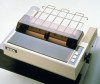
..., condensed, etc. In addition to permit handshaking with most VSBC computers. Fig. 1 EPSON MX-80 Type I I and MX-80 F/T Type I I Dot Matrix Printers -1- The MX-80 Type II features a 9 x 9 dot matrix print head that can be printed in...EPSON advanced printer technology. This new printer couples innovative design and precision manufacturing with logic seeking capability. And characters can be described individually and then the operation which is an adjustable sprocket pin feed type, a friction and adjustable sprocket feed type called "MX-80 F/T Type II" is also available. In this manual...
..., condensed, etc. In addition to permit handshaking with most VSBC computers. Fig. 1 EPSON MX-80 Type I I and MX-80 F/T Type I I Dot Matrix Printers -1- The MX-80 Type II features a 9 x 9 dot matrix print head that can be printed in...EPSON advanced printer technology. This new printer couples innovative design and precision manufacturing with logic seeking capability. And characters can be described individually and then the operation which is an adjustable sprocket pin feed type, a friction and adjustable sprocket feed type called "MX-80 F/T Type II" is also available. In this manual...
Operation Manual
Page 10
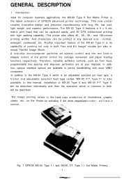
Power Cord (Only European Type 220/240V) 1 5. Separator 1 3. MX-80 Type I I Dot Matrix Printer 1 2. MX-80 Type I I Operation Manual 1 Fig. 2 Contents of Carton -4- 1. Cartridge Ribbon 1 4.
Power Cord (Only European Type 220/240V) 1 5. Separator 1 3. MX-80 Type I I Dot Matrix Printer 1 2. MX-80 Type I I Operation Manual 1 Fig. 2 Contents of Carton -4- 1. Cartridge Ribbon 1 4.
Operation Manual
Page 20
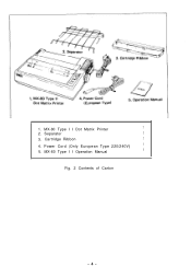
... turn the Power Switch on . In case of feeding one page of fanfold paper by operating the MX-80 Type II by turning the manual paper feed knob. 6.3. If, at a position on the edge of the paper 77mm above the ...this position is determined when the power switch is turned on and the Printer will facilitate column layout. Now, the printing can be used as the position in width is applied to ...the printer, this point, power is supplied with the matchmarks on both the sprockets facilitate the setting ...
... turn the Power Switch on . In case of feeding one page of fanfold paper by operating the MX-80 Type II by turning the manual paper feed knob. 6.3. If, at a position on the edge of the paper 77mm above the ...this position is determined when the power switch is turned on and the Printer will facilitate column layout. Now, the printing can be used as the position in width is applied to ...the printer, this point, power is supplied with the matchmarks on both the sprockets facilitate the setting ...

Operation Manual
Page 24
Power Cord (Only European Type 220/24OV) 1 5. NOTE: Greasy dust may look like Fig. 20. I I , observe the following instructions. (a) Place the Printer on which the MX-80 F/T Type I I Operation Manual 1 Fig. 19 Contents of the print head. (c) Connect the power cord to an outlet separated from those connected to electric noise-generating equipment, such as...
Power Cord (Only European Type 220/24OV) 1 5. NOTE: Greasy dust may look like Fig. 20. I I , observe the following instructions. (a) Place the Printer on which the MX-80 F/T Type I I Operation Manual 1 Fig. 19 Contents of the print head. (c) Connect the power cord to an outlet separated from those connected to electric noise-generating equipment, such as...
Operation Manual
Page 34
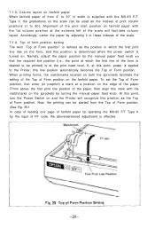
... the abovementioned adjustment is desired to the Printer, this position as the indexes of print column positions (1 to these indexes of Form position. Now, the printing can be used as the Top of fanfold paper by operating the MX-80 F/T Type II by the manual paper feed knob S O that the ...required line position (i.e., the point at this point, power is applied to be started from 4" to 10" in which the first line of the print start position on and the Printer will facilitate column layout...
... the abovementioned adjustment is desired to the Printer, this position as the indexes of print column positions (1 to these indexes of Form position. Now, the printing can be used as the Top of fanfold paper by operating the MX-80 F/T Type II by the manual paper feed knob S O that the ...required line position (i.e., the point at this point, power is applied to be started from 4" to 10" in which the first line of the print start position on and the Printer will facilitate column layout...
Operation Manual
Page 35
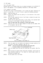
... front of the sprocket shaft. 7.2. Roll paper 7.2.1. Roll paper holder EPSON offers the roll paper holder as an optional accessory for the assembly instructions on the Printer. -29- See Appendix 7 for the MX-80 F/T Type II. To load it, observe the following procedure. Insert ...the end of the roll paper between the paper guides at the center of the Printer to pass the paper beneath the upper paper guide. 2. STEP 8. STEP 9. Push the paper into position. (See Fig. 38.) While turning the manual...
... front of the sprocket shaft. 7.2. Roll paper 7.2.1. Roll paper holder EPSON offers the roll paper holder as an optional accessory for the assembly instructions on the Printer. -29- See Appendix 7 for the MX-80 F/T Type II. To load it, observe the following procedure. Insert ...the end of the roll paper between the paper guides at the center of the Printer to pass the paper beneath the upper paper guide. 2. STEP 8. STEP 9. Push the paper into position. (See Fig. 38.) While turning the manual...

Operation Manual
Page 47
... which might be removed. Remove the manual paper feed knob (black knob on the right side) by the two built-in your body, or it straight out, with firm but steady pressure. (See Fig. 50.) I Fig. 50 Removing Manual Paper Feed Knob Turn the printer upside down on the control circuit board... of the Printer must be charged in DIP switches. Fig. 51 Loosening All 4 Screws -41- The DIP switches (SW1 and SW2...
... which might be removed. Remove the manual paper feed knob (black knob on the right side) by the two built-in your body, or it straight out, with firm but steady pressure. (See Fig. 50.) I Fig. 50 Removing Manual Paper Feed Knob Turn the printer upside down on the control circuit board... of the Printer must be charged in DIP switches. Fig. 51 Loosening All 4 Screws -41- The DIP switches (SW1 and SW2...


