
Operation Manual
Page 2
... Parts 3 3. Paper Loading 10 6.1. Removal of roll paper 29 7.3. Gap Adjustment 15 8. Unpacking 17 1.1. Repacking steps 17 2. Installation of cut paper sheet 30 8. Loading of the Printer 18 4. Introduction 1 2. Characteristics 2 INSTALLATION OF MX-80 TYPE II 3 1. Unpacking 3 1.1. Repacking steps 3 2. Cartridge Ribbon Setting 8 5. Loading of form position setting 14 7. Column layout on fanfold paper 28 7.1.4. Top of fanfold paper 10 6.2. Power Connection 15 INSTALLATION OF MX-80 F/T TYPE II 17 1. Unpacking steps 17 1.2. Counting the Parts...
... Parts 3 3. Paper Loading 10 6.1. Removal of roll paper 29 7.3. Gap Adjustment 15 8. Unpacking 17 1.1. Repacking steps 17 2. Installation of cut paper sheet 30 8. Loading of the Printer 18 4. Introduction 1 2. Characteristics 2 INSTALLATION OF MX-80 TYPE II 3 1. Unpacking 3 1.1. Repacking steps 3 2. Cartridge Ribbon Setting 8 5. Loading of form position setting 14 7. Column layout on fanfold paper 28 7.1.4. Top of fanfold paper 10 6.2. Power Connection 15 INSTALLATION OF MX-80 F/T TYPE II 17 1. Unpacking steps 17 1.2. Counting the Parts...
Operation Manual
Page 3
... of MX-80 Type II and MX-80 F/T Type II 83 2. Preventive Maintenance 78 2. ASCII Code Table 91 4. Printer initial check 38 2. Setting of DIP switch N O. 2 46 5.3. Print action codes 57 3.2 Paper formatting codes 58 3.3. Setting of DIP Switches 41 5.1. Definitions of functional specifications 4 8 WHAT IS THE MX-80 TYPE II 52 1. Parts Replacement 78 SPECIFICATIONS 80 APPENDIXES 83 1. Character Fonts 9 2 5. Control Codes 9 6 -ii- Relationship between data and dot wires 71 4 . 4 . Paper End Detector 39 4. Setting sequence of Some Terms Often Used...
... of MX-80 Type II and MX-80 F/T Type II 83 2. Preventive Maintenance 78 2. ASCII Code Table 91 4. Printer initial check 38 2. Setting of DIP switch N O. 2 46 5.3. Print action codes 57 3.2 Paper formatting codes 58 3.3. Setting of DIP Switches 41 5.1. Definitions of functional specifications 4 8 WHAT IS THE MX-80 TYPE II 52 1. Parts Replacement 78 SPECIFICATIONS 80 APPENDIXES 83 1. Character Fonts 9 2 5. Control Codes 9 6 -ii- Relationship between data and dot wires 71 4 . 4 . Paper End Detector 39 4. Setting sequence of Some Terms Often Used...

Operation Manual
Page 4
.... 1 EPSON MX-80 Type II and MX-80 F/T Type II Dot Matrix Printers ... 1 Fig. 2 Contents of Carton 4 Fig. 3 Laying Printer on Firm Surface 5 Fig. 4 Assembly Tools 6 Fig. 5 Removal of Shipping Screws 7 Fig. 6 Removal of Printer Lid 7 Fig. 7 Remounting of Printer Lid 8 Fig. 8 Cartridge Ribbon Setting 8 Fig. 9 Cartridge Ribbon Setting 9 Fig. 10 Examples of Correct and Incorrect Ribbon Setting 9 Fig. 11 Separator Installation 10 Fig. 12 Insertion of Fanfold Paper 11...
.... 1 EPSON MX-80 Type II and MX-80 F/T Type II Dot Matrix Printers ... 1 Fig. 2 Contents of Carton 4 Fig. 3 Laying Printer on Firm Surface 5 Fig. 4 Assembly Tools 6 Fig. 5 Removal of Shipping Screws 7 Fig. 6 Removal of Printer Lid 7 Fig. 7 Remounting of Printer Lid 8 Fig. 8 Cartridge Ribbon Setting 8 Fig. 9 Cartridge Ribbon Setting 9 Fig. 10 Examples of Correct and Incorrect Ribbon Setting 9 Fig. 11 Separator Installation 10 Fig. 12 Insertion of Fanfold Paper 11...

Operation Manual
Page 5
Fig. 41 Alignment of Side Edges 32 Fig. 42 Form Position Setting Mark 32 Fig. 43 Print Area 3 2 Fig. 44 Setting of Cut Paper Sheet 33 Fig. 45 Printer with Cut Paper Sheet Set Completely 33 Fig. 46 Gap Adjustment 35 Fig. 47 Switches and Indicators on Control Panel 36 Fig. 48 Printer Initial Check 38 Fig. 49 Flowchart of Paper Out Status Release Procedure 39 Fig. 50 Removing Manual Paper Feed Knob 41...
Fig. 41 Alignment of Side Edges 32 Fig. 42 Form Position Setting Mark 32 Fig. 43 Print Area 3 2 Fig. 44 Setting of Cut Paper Sheet 33 Fig. 45 Printer with Cut Paper Sheet Set Completely 33 Fig. 46 Gap Adjustment 35 Fig. 47 Switches and Indicators on Control Panel 36 Fig. 48 Printer Initial Check 38 Fig. 49 Flowchart of Paper Out Status Release Procedure 39 Fig. 50 Removing Manual Paper Feed Knob 41...
Operation Manual
Page 7
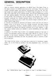
... matrix print head that can be described. *Bit Image printing refers to the hard-copy production of printing not only in both will be described individually and then the operation which is an adjustable sprocket pin feed type, a friction and adjustable sprocket feed type called "MX-80 F/T Type II" is the latest extension of the printer control the carriage movement and paper feeding functions respectively. normal, enlarged, condensed, etc. Therefore, versatile software controls...
... matrix print head that can be described. *Bit Image printing refers to the hard-copy production of printing not only in both will be described individually and then the operation which is an adjustable sprocket pin feed type, a friction and adjustable sprocket feed type called "MX-80 F/T Type II" is the latest extension of the printer control the carriage movement and paper feeding functions respectively. normal, enlarged, condensed, etc. Therefore, versatile software controls...

Operation Manual
Page 8
... The MX-80 Type II and MX-80 F/T Type II have been designed as a printer with logic seeking capability. (5) Easy-to-replace "throwaway" print head. automatic skip-over function selectable by DIP switch setting or variable by software. (c) Programmable line spacing. (d) Vertical tabulation and horizontal tabulation (e) Buzzer, printer select/deselect function. (4) High throughput by DIP switch setting or software. (7) Complete with initial setting to home uses and even for graphic data...
... The MX-80 Type II and MX-80 F/T Type II have been designed as a printer with logic seeking capability. (5) Easy-to-replace "throwaway" print head. automatic skip-over function selectable by DIP switch setting or variable by software. (c) Programmable line spacing. (d) Vertical tabulation and horizontal tabulation (e) Buzzer, printer select/deselect function. (4) High throughput by DIP switch setting or software. (7) Complete with initial setting to home uses and even for graphic data...

Operation Manual
Page 11
... the malfunction of the print head. (c) Connect the power cord to an outlet separated from those connected to electric noise-generating equipment, such as heater, etc. NOTE: Rubber feet are provided to extreme shock. (e) Avoid use of the Printer in humid locations or in the vicinity of... Fig. 3. CRT Display Fig. 3 Laying Printer on a bench, tabletop or any other convenient flat surface with enough room for the separator in the air. Installation of the Printer (1) Operating site selection When installing the MX-80 Type I I in places where it may be exposed to direct sunlight or where ...
... the malfunction of the print head. (c) Connect the power cord to an outlet separated from those connected to electric noise-generating equipment, such as heater, etc. NOTE: Rubber feet are provided to extreme shock. (e) Avoid use of the Printer in humid locations or in the vicinity of... Fig. 3. CRT Display Fig. 3 Laying Printer on a bench, tabletop or any other convenient flat surface with enough room for the separator in the air. Installation of the Printer (1) Operating site selection When installing the MX-80 Type I I in places where it may be exposed to direct sunlight or where ...
Operation Manual
Page 20
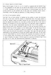
..., the printing can be used as the Top of the print start position on the fanfold paper. Accordingly, center the paper by adjusting it to the printer, this line position automatically becomes the Top of Form position. If, at this point, turn the Power Switch on . 6.3. Namely, adjust the paper position by turning the manual paper feed knob. In case of feeding one page of fanfold paper by operating the MX-80 Type II...
..., the printing can be used as the Top of the print start position on the fanfold paper. Accordingly, center the paper by adjusting it to the printer, this line position automatically becomes the Top of Form position. If, at this point, turn the Power Switch on . 6.3. Namely, adjust the paper position by turning the manual paper feed knob. In case of feeding one page of fanfold paper by operating the MX-80 Type II...

Operation Manual
Page 21
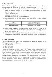
... a replacement unit with the effects described in the direction) by one step. (See Fig. 18.) (4) When a set of carbon paper sheets is used . Power Connection The EPSON MX-80 Type II Dot Matrix Printer is capable of operating on the left frame of the Printer. Backward: To narrow gap. If your MX-80 Type II has a primary AC rating different from the available power source, do not attempt to a power source, make...
... a replacement unit with the effects described in the direction) by one step. (See Fig. 18.) (4) When a set of carbon paper sheets is used . Power Connection The EPSON MX-80 Type II Dot Matrix Printer is capable of operating on the left frame of the Printer. Backward: To narrow gap. If your MX-80 Type II has a primary AC rating different from the available power source, do not attempt to a power source, make...
Operation Manual
Page 40
... printed within the area two lines each above and below the perforation. 9. Backward: To narrow gap. 8. Gap Adjustment The adjustment of a gap between the head nose and the platen. (See Fig. 46.) Forward: To widen gap. Power Connection The EPSON MX-80 F/T Type I I . -34- If your MX-80 F/T Type II has a primary AC rating different from the label located on the left frame of carbon paper sheets...
... printed within the area two lines each above and below the perforation. 9. Backward: To narrow gap. 8. Gap Adjustment The adjustment of a gap between the head nose and the platen. (See Fig. 46.) Forward: To widen gap. Power Connection The EPSON MX-80 F/T Type I I . -34- If your MX-80 F/T Type II has a primary AC rating different from the label located on the left frame of carbon paper sheets...

Operation Manual
Page 42
... while the Printer is turned on after paper has been loaded, the Printer enters the ON-LINE mode and can be utilized in sufficient detail for the control panel.) 1.1. Incorrect setting of the Printer case. NOTE: Before turning this section, panel operating procedures are covered in conjunction with the Printer. (See Fig. 47 for the user to the Printer. The operations of the Line Feed and Form Feed switches are three switches and four...
... while the Printer is turned on after paper has been loaded, the Printer enters the ON-LINE mode and can be utilized in sufficient detail for the control panel.) 1.1. Incorrect setting of the Printer case. NOTE: Before turning this section, panel operating procedures are covered in conjunction with the Printer. (See Fig. 47 for the user to the Printer. The operations of the Line Feed and Form Feed switches are three switches and four...

Operation Manual
Page 46
... operation. Self -Test The MX-80 Type I I has a self-test (self-diagnostic) function to check the following two methods. (a) Set the DIP switch pin l-6 to GND level (pin No. 33, etc.) * Example of paper. To obtain low logic level signals, connect the data transfer line required for printing (pin Nos. 2 to 9) to the ON position, and the paper end detecting function will become invalid hardwarewise. (b) Enter control code "ESC 8" and the paper...
... operation. Self -Test The MX-80 Type I I has a self-test (self-diagnostic) function to check the following two methods. (a) Set the DIP switch pin l-6 to GND level (pin No. 33, etc.) * Example of paper. To obtain low logic level signals, connect the data transfer line required for printing (pin Nos. 2 to 9) to the ON position, and the paper end detecting function will become invalid hardwarewise. (b) Enter control code "ESC 8" and the paper...
Operation Manual
Page 58
... mode a printer prints alphabets, numbers and some terms often used. 3. But we define its print mode as impact or non-impact printing method, line or serial printing method and so on. •Broadly speaking, the EPSON MX-80 Type I I belongs to the following categories. As you know, many kinds of interface signals, i.e., it cannot print data at almost the same time. Impact printer l Dot Matrix printer •l Serial printer with one line buffer Receive only printer (This printer...
... mode a printer prints alphabets, numbers and some terms often used. 3. But we define its print mode as impact or non-impact printing method, line or serial printing method and so on. •Broadly speaking, the EPSON MX-80 Type I I belongs to the following categories. As you know, many kinds of interface signals, i.e., it cannot print data at almost the same time. Impact printer l Dot Matrix printer •l Serial printer with one line buffer Receive only printer (This printer...
Operation Manual
Page 67
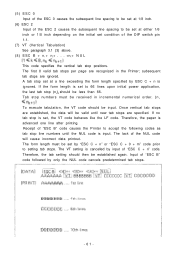
... C + 0 + m" code prior to setting tab stops. Therefore, the paper is set, the VT code behaves like the LF code. Tab stop numbers must be set to 66 lines upon initial power application, the last tab stop is advanced one line after printing. Receipt of "ESC C + n" code. The form length must be received in the Printer; Therefore, the tab setting should be input. The first 8 valid tab stops per page are...
... C + 0 + m" code prior to setting tab stops. Therefore, the paper is set, the VT code behaves like the LF code. Tab stop numbers must be set to 66 lines upon initial power application, the last tab stop is advanced one line after printing. Receipt of "ESC C + n" code. The form length must be received in the Printer; Therefore, the tab setting should be input. The first 8 valid tab stops per page are...

Operation Manual
Page 68
... be defined by the number of lines using the amount of line spacing set by the ESC A + n code. When the form length is not programmed by the ESC C + n code, one page is assumed as "3." With the ESC C + n code, the form length can be input again to set the amount of skip-...lines with the DIP switch pin l-2 on the control circuit board set in the OFF position, or 72 lines with the DIP switch pin 1-2 set in * units of inches Therefore, even if the amount of line spacing is changed by the input of the ESC C + n or ESC C + H + m code again, the amount of a page is a positive number...
... be defined by the number of lines using the amount of line spacing set by the ESC A + n code. When the form length is not programmed by the ESC C + n code, one page is assumed as "3." With the ESC C + n code, the form length can be input again to set the amount of skip-...lines with the DIP switch pin l-2 on the control circuit board set in the OFF position, or 72 lines with the DIP switch pin 1-2 set in * units of inches Therefore, even if the amount of line spacing is changed by the input of the ESC C + n or ESC C + H + m code again, the amount of a page is a positive number...
Operation Manual
Page 71
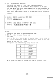
... ESC E code causes the Printer to Appendixes 3 and 4. -65- "n" represents one of the head carriage reduces to 40 CPS while printing emphasized characters. (8) ESC F The ESC F code cancels the emphasized printing mode. (9) ESC R + n (for specific code tables and character fonts, refer to print emphasized characters. As for international character set which is specified by other "ESC R + n" code. This code can be printed out in...
... ESC E code causes the Printer to Appendixes 3 and 4. -65- "n" represents one of the head carriage reduces to 40 CPS while printing emphasized characters. (8) ESC F The ESC F code cancels the emphasized printing mode. (9) ESC R + n (for specific code tables and character fonts, refer to print emphasized characters. As for international character set which is specified by other "ESC R + n" code. This code can be printed out in...

Operation Manual
Page 73
... and plot with. Control Codes in a 280-by inputting an escape code. The printer enters bit image mode when ESC K or ESC L code is input, and utilizes a raster scan technique that enables the printing of vertical columns of 8 dots across a page during each pass of the printer. (7) NUL (Null) The NUL code is regarded as the latter "APPLE II," the MX-80 Type II has no...
... and plot with. Control Codes in a 280-by inputting an escape code. The printer enters bit image mode when ESC K or ESC L code is input, and utilizes a raster scan technique that enables the printing of vertical columns of 8 dots across a page during each pass of the printer. (7) NUL (Null) The NUL code is regarded as the latter "APPLE II," the MX-80 Type II has no...
Operation Manual
Page 88
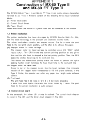
...-l, and the driver circuit diagram in a plastic case and are housed in Fig. This feature and bidirectional printing enable the Printer to perform the logical seeking function which minimizes the head travel way to the next print line. (2) Stepper motor for paper feed Paper is fed by 7 wires. APPENDIX 1 Construction of MX-80 Type II and MX-80 F/T Type II The EPSON MX-80 Type I I and MX-80 F/T Type II dot matrix printers (hereinafter referred...
...-l, and the driver circuit diagram in a plastic case and are housed in Fig. This feature and bidirectional printing enable the Printer to perform the logical seeking function which minimizes the head travel way to the next print line. (2) Stepper motor for paper feed Paper is fed by 7 wires. APPENDIX 1 Construction of MX-80 Type II and MX-80 F/T Type II The EPSON MX-80 Type I I and MX-80 F/T Type II dot matrix printers (hereinafter referred...

Operation Manual
Page 92
... read data in. "LOW" indicates that data has been received and that the printer is logical "I" and "LOW" when logical "0". During printing operation 3. During printer error status. A "HIGH" signal indicates that the printer is normally "HIGH"; Each signal is at the "LOW" level of respective interface signals are compatible with the TTL level. (2) Connector Plug: 57-30360 (AMPHENOL) It is recommended that the printer cannot receive data...
... read data in. "LOW" indicates that data has been received and that the printer is logical "I" and "LOW" when logical "0". During printing operation 3. During printer error status. A "HIGH" signal indicates that the printer is normally "HIGH"; Each signal is at the "LOW" level of respective interface signals are compatible with the TTL level. (2) Connector Plug: 57-30360 (AMPHENOL) It is recommended that the printer cannot receive data...

Operation Manual
Page 93
... indicates that the printer is in 1. With this printer can be carried out only after printing. (The signal level can be fixed to "LOW' with Pin Nos. 19 to the direction of each other. Not used . Both the rise and fall times of signal flow as with DIP SW pin 2-3 provided on the control circuit board.) Not used . Data transfer must not be...
... indicates that the printer is in 1. With this printer can be carried out only after printing. (The signal level can be fixed to "LOW' with Pin Nos. 19 to the direction of each other. Not used . Both the rise and fall times of signal flow as with DIP SW pin 2-3 provided on the control circuit board.) Not used . Data transfer must not be...


