Technical Brief (Impact Printers)
Page 4
...Each EPSON impact printer includes a variety of built-in 2-point increments, available on EPSON 24-pin impact printers Barcode fonts-available on most EPSON impact printers offer EPSON Type B interface slots that are the property of their respective owners. EPSON Sales Training EPSON is added, EPSON impact printers automatic ...trademarks are available on a printer. After a document is torn off Can be automatic or activated by pressing a button on the control panel. Bundled Microsoft Windows® 3.1x, Windows NT 3.51/4.0, Windows 95 and Windows 98 drivers guarantees ease of use ...
...Each EPSON impact printer includes a variety of built-in 2-point increments, available on EPSON 24-pin impact printers Barcode fonts-available on most EPSON impact printers offer EPSON Type B interface slots that are the property of their respective owners. EPSON Sales Training EPSON is added, EPSON impact printers automatic ...trademarks are available on a printer. After a document is torn off Can be automatic or activated by pressing a button on the control panel. Bundled Microsoft Windows® 3.1x, Windows NT 3.51/4.0, Windows 95 and Windows 98 drivers guarantees ease of use ...
Product Information Guide
Page 4
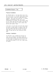
... work properly if LX, RX, MX, or Epson drivers are routed away from both incoming and exiting paper. DFX-5000 4 12/12/88 9 - Pin Printers MATRIX PRINTER Installation/Support Tips Physical Installation The DFX-5000 printer is a very easy printer to set up, but due to the fact that a proper paper path is established. Epson printer stand model 8501 -A is properly aligned (no...
... work properly if LX, RX, MX, or Epson drivers are routed away from both incoming and exiting paper. DFX-5000 4 12/12/88 9 - Pin Printers MATRIX PRINTER Installation/Support Tips Physical Installation The DFX-5000 printer is a very easy printer to set up, but due to the fact that a proper paper path is established. Epson printer stand model 8501 -A is properly aligned (no...
Service Manual
Page 9
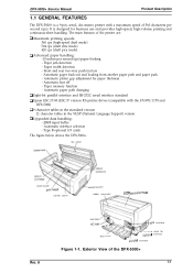
...- Automatic paper path changing Cl Eight-bit parallel interface and RS-232C serial interface standard Cl Epson ESC/P-83 (ESC/P version 83) printer driver (compatible with a maximum speed of the DFX-5000+ 1-1 Automatic platen gap adjustment for paper thickness - Automatic interface selection - Paper width detection... use and provides high-speed, high-volume printing and continuous-sheet handling. It is a 9-pin, serial, dot matrix printer with the FX-870/1170 and DFX-5000) D 9 character tables in the standard version 21 character tables in the NLSP (National Language Support) version ...
...- Automatic paper path changing Cl Eight-bit parallel interface and RS-232C serial interface standard Cl Epson ESC/P-83 (ESC/P version 83) printer driver (compatible with a maximum speed of the DFX-5000+ 1-1 Automatic platen gap adjustment for paper thickness - Automatic interface selection - Paper width detection... use and provides high-speed, high-volume printing and continuous-sheet handling. It is a 9-pin, serial, dot matrix printer with the FX-870/1170 and DFX-5000) D 9 character tables in the standard version 21 character tables in the NLSP (National Language Support) version ...

Service Manual
Page 30
... 5 sek of 4 beeps) *"* (3 beeps) * **•" (sbeepswi~ a w= ~tween each beep) ~? ~ - ** q * - ** ** (B *S of z beeps) *** (4 beeps) A short circuited printhead is detected. (The head driver FETs are bad.) A short circuited printhead fan is ready to : - An illegal paper memory setting is detected. * * * * q q * * q * (II) &P ~~ a Pam between each beep) ** w ** ** q * (5...paper out or paper jam is detected. A cover open is turned on .) An abnormal voltage is detected. (The printer runs out of 3 *) Note: ** 0.1 second interval * *0.3 sWmd interval 1-22 Rev. Clears the print buffer...
... 5 sek of 4 beeps) *"* (3 beeps) * **•" (sbeepswi~ a w= ~tween each beep) ~? ~ - ** q * - ** ** (B *S of z beeps) *** (4 beeps) A short circuited printhead is detected. (The head driver FETs are bad.) A short circuited printhead fan is ready to : - An illegal paper memory setting is detected. * * * * q q * * q * (II) &P ~~ a Pam between each beep) ** w ** ** q * (5...paper out or paper jam is detected. A cover open is turned on .) An abnormal voltage is detected. (The printer runs out of 3 *) Note: ** 0.1 second interval * *0.3 sWmd interval 1-22 Rev. Clears the print buffer...

Service Manual
Page 36
... RF) figure 1-28. S,22,10,13,16,i4,16,20,21(dnv.r for PRINTHEAD) L Q28 031(dnvor for the CR motor, each driver's IC, and the parallel and serial interface control circuits. f o 4- C117 PSWPSE Board Assembly 1-28 Rev. A C117 MAIN Board Assembly 1.6.3 Power... Supply Circuit (C117 PSB/PSE Board Assembly) The C117 PSB/PSE tmrd assembly power supply circuit supplies the control circuit and printer mechanism drive circuit with power. CN1O CN7 CN9 + t 1' \ : g-lc;-$:,,RAM, \ I-41, u a ,1 0 o 0 0 nn0 0o0 &0 ,-E~ , m n : IC1(CPU:TMPWC14) lC2fEEPROM ...
... RF) figure 1-28. S,22,10,13,16,i4,16,20,21(dnv.r for PRINTHEAD) L Q28 031(dnvor for the CR motor, each driver's IC, and the parallel and serial interface control circuits. f o 4- C117 PSWPSE Board Assembly 1-28 Rev. A C117 MAIN Board Assembly 1.6.3 Power... Supply Circuit (C117 PSB/PSE Board Assembly) The C117 PSB/PSE tmrd assembly power supply circuit supplies the control circuit and printer mechanism drive circuit with power. CN1O CN7 CN9 + t 1' \ : g-lc;-$:,,RAM, \ I-41, u a ,1 0 o 0 0 nn0 0o0 &0 ,-E~ , m n : IC1(CPU:TMPWC14) lC2fEEPROM ...

Service Manual
Page 38
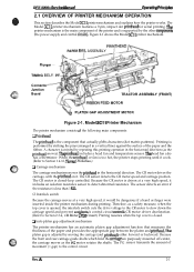
CHAPTER 2 Operating Principles Table of Contents 2.1 OVERVIEW OF PRINTER MECHANISM OPERATION 2-1 2.1.1 Printhead Mechanism 2-3 2.1.2 Carriage Mechanism 2-4 2.1.3 Platen Gap Adjustment Mechanism 2-5 2.1.4 Paper Feed Mechanism 2-6 2.1.4.1 Tractor Wire ...CIRCUIT 2-17 2.3.1 Control Circuit Operation Overview 2-17 2.3.2 Reset Circuit 2-21 2.3.3 Sensor Circuits 2-Z 2.3.4 CR Motor Driver Cimufi 2-25 2.3.5 PF Motor Driver Cimuit 2-30 2.3.6 RF Motor Driver Circuit 2-31 2.3.7 PG Motor Driver Circuit 2-32 2.3.8 Plunger Driver Circuit 2-33 2.3.9 Printhead Driver Circuit 2-33 c) 62
CHAPTER 2 Operating Principles Table of Contents 2.1 OVERVIEW OF PRINTER MECHANISM OPERATION 2-1 2.1.1 Printhead Mechanism 2-3 2.1.2 Carriage Mechanism 2-4 2.1.3 Platen Gap Adjustment Mechanism 2-5 2.1.4 Paper Feed Mechanism 2-6 2.1.4.1 Tractor Wire ...CIRCUIT 2-17 2.3.1 Control Circuit Operation Overview 2-17 2.3.2 Reset Circuit 2-21 2.3.3 Sensor Circuits 2-Z 2.3.4 CR Motor Driver Cimufi 2-25 2.3.5 PF Motor Driver Cimuit 2-30 2.3.6 RF Motor Driver Circuit 2-31 2.3.7 PG Motor Driver Circuit 2-32 2.3.8 Plunger Driver Circuit 2-33 2.3.9 Printhead Driver Circuit 2-33 c) 62

Service Manual
Page 39
Half-wave Rectifier Circuit 2-16 Figure 2-18. Reset Circuit Block Diagram 2-21 Figure 2-21. CR Motor Driver Block Diagram 2-25 Figure 2-24. PG Motor Driver Circuit 2-32 Figure 2-30. CR Motor Drive Modes 2-26 Table 2-5. Printer Mechanism Operation 2 2-3 Figure 2-4. Platen GapAdjustment Mechanism 2-5 Figure 2-7. Data Flow from the Parallel Interface 2-19 Figure2-20. Measurement Sequence...
Half-wave Rectifier Circuit 2-16 Figure 2-18. Reset Circuit Block Diagram 2-21 Figure 2-21. CR Motor Driver Block Diagram 2-25 Figure 2-24. PG Motor Driver Circuit 2-32 Figure 2-30. CR Motor Drive Modes 2-26 Table 2-5. Printer Mechanism Operation 2 2-3 Figure 2-4. Platen GapAdjustment Mechanism 2-5 Figure 2-7. Data Flow from the Parallel Interface 2-19 Figure2-20. Measurement Sequence...
Service Manual
Page 40
...cover is driven at a very high speed, it . The Model 3C11 printer mechanism features a 9-pin, impact dot printhead for serial printing. A control circuit controIs CR motor driver deceleration. (Refer to Section 1.4.12, Themud Probation.) L1 Carnage mechanism The ...automatic platen gap adjustment function that actually pMts characters (dot matrix patterns). DFx-5tW(h Sewka Manual Oparathg Prfncipka 2.1 OVERVIEW OF PRINTER MECHANISM OPERATION This section describes the Model 3C11 printer mechanism and explains how the printer works. PAPER BA~L ASSEMBLY Plunger TIMING BEL Connector...
...cover is driven at a very high speed, it . The Model 3C11 printer mechanism features a 9-pin, impact dot printhead for serial printing. A control circuit controIs CR motor driver deceleration. (Refer to Section 1.4.12, Themud Probation.) L1 Carnage mechanism The ...automatic platen gap adjustment function that actually pMts characters (dot matrix patterns). DFx-5tW(h Sewka Manual Oparathg Prfncipka 2.1 OVERVIEW OF PRINTER MECHANISM OPERATION This section describes the Model 3C11 printer mechanism and explains how the printer works. PAPER BA~L ASSEMBLY Plunger TIMING BEL Connector...

Service Manual
Page 52
... power is turned off , wait three minutes before you turn it outputs +13 VDC to the printhead drivers on the board type (120 V C117 MB or 220/240 V C117 PSE). e m %i;' DFX-5000+ Sendee Mama! To prevent a surge in the current, the power supply board cannot recover for printhead ...firing Note: Before the power supply board outputs +35 VDC, it back on the DRERR (Driver Error) signal from the C117 MAIN board assembly, and output the CLIMIT (Power Down) signal when the printer ...
... power is turned off , wait three minutes before you turn it outputs +13 VDC to the printhead drivers on the board type (120 V C117 MB or 220/240 V C117 PSE). e m %i;' DFX-5000+ Sendee Mama! To prevent a surge in the current, the power supply board cannot recover for printhead ...firing Note: Before the power supply board outputs +35 VDC, it back on the DRERR (Driver Error) signal from the C117 MAIN board assembly, and output the CLIMIT (Power Down) signal when the printer ...
Service Manual
Page 53
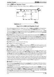
...-2 Figure 2-15. +5 VDC Line Regulator Circuit The rectified and smoothed DC voltage turns on the C117 MAIN board assembly. When the printer is a common circuit with the DRERR signal feedback circuit on the +5 VDC line first. When the power supply board receives this signal... C2 ports. Cl Printhead driver detection circuit This circuit prevents printhead damage when a printhead driver is damaged. If the printhead drivers are normal, the C117 MAIN board assembIy sends the VPC signal to the C117 power supply board assembly. Operating Principles DFX-5000+ Service Manual 2.2.2 +5 ...
...-2 Figure 2-15. +5 VDC Line Regulator Circuit The rectified and smoothed DC voltage turns on the C117 MAIN board assembly. When the printer is a common circuit with the DRERR signal feedback circuit on the +5 VDC line first. When the power supply board receives this signal... C2 ports. Cl Printhead driver detection circuit This circuit prevents printhead damage when a printhead driver is damaged. If the printhead drivers are normal, the C117 MAIN board assembIy sends the VPC signal to the C117 power supply board assembly. Operating Principles DFX-5000+ Service Manual 2.2.2 +5 ...

Service Manual
Page 55
... and then the input voltage is LOW. Therefore, six Zener diodes create the +35 VDC. A Cl +13 VDC creation circuit When the printer is turned off . During the motor driver check, the VPC signal is cut Rectifier Smoothing Circuit Circuit C+ Icuit o I I J 4) TF -:== "~ OverCurrent Protection Main switching Circuit ... power from the half-wave rectifier smoothing circuit is turned off . o FMer Circuit surge-cut . When the printer is operated during the printhead driver check, the power supply board cannot be turned on Q153 (Q253). When the over-current flows to the base...
... and then the input voltage is LOW. Therefore, six Zener diodes create the +35 VDC. A Cl +13 VDC creation circuit When the printer is turned off . During the motor driver check, the VPC signal is cut Rectifier Smoothing Circuit Circuit C+ Icuit o I I J 4) TF -:== "~ OverCurrent Protection Main switching Circuit ... power from the half-wave rectifier smoothing circuit is turned off . o FMer Circuit surge-cut . When the printer is operated during the printhead driver check, the power supply board cannot be turned on Q153 (Q253). When the over-current flows to the base...

Service Manual
Page 56
... by writing directly to provide back-up control of the non-volatile memory (when the printer is turned off , the voltage level drops, or a reset signal is turned on ...down), are : ~ (Chip Select) signal creation, address decodina printhead driver control, carriage driver control, encoder pulse arcuit control, PG and c~....\.,., % fan motor phase signal creation, interface control, CR...voltage. The CPU starts executing a program upon r-iving the reset signal from an external device. DEX-5000+ Servics Manual @wating *"ncipba 2.3 CONTROL CIRCUIT Figure 2-18 shows a block diagram of the control ...
... by writing directly to provide back-up control of the non-volatile memory (when the printer is turned off , the voltage level drops, or a reset signal is turned on ...down), are : ~ (Chip Select) signal creation, address decodina printhead driver control, carriage driver control, encoder pulse arcuit control, PG and c~....\.,., % fan motor phase signal creation, interface control, CR...voltage. The CPU starts executing a program upon r-iving the reset signal from an external device. DEX-5000+ Servics Manual @wating *"ncipba 2.3 CONTROL CIRCUIT Figure 2-18 shows a block diagram of the control ...
Service Manual
Page 58
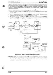
... clear the BUSY signal and output the ACKNLG signal, via the parallel interface. Yes -: + e Yes ')o BUSY or IACK L .......... AHribute T Printer Mechanism Driver o8 + Character Generator I Down Load ""; A 2-19 Data from the Parallel Interface 4. DFX-5000+ Servics Mimml 0per8thg Ffinchl&e Figure 2-19 shows the data flow for data input via the MMIO accesses. Although various...
... clear the BUSY signal and output the ACKNLG signal, via the parallel interface. Yes -: + e Yes ')o BUSY or IACK L .......... AHribute T Printer Mechanism Driver o8 + Character Generator I Down Load ""; A 2-19 Data from the Parallel Interface 4. DFX-5000+ Servics Mimml 0per8thg Ffinchl&e Figure 2-19 shows the data flow for data input via the MMIO accesses. Although various...

Service Manual
Page 59
...to -fetch operation. When the CPU expands the data from the print data in units of one line consists of the main printer components. Whenever the input data buffer is not full between printing operations, data is always ready to fetch data so printing can...E05A87 features are: Q CS (Chip Select) signal creation D Address decoding Q Address latching Cl Clock pulse creation (divided from the CPU clock) Q Printhead driver control D CR motor driver control LI CR and PG motor pulse encoder l/O (input/output) Q Encoder pulse 1/0 Q Phase signal creation for the motors Q i/O port control Q ...
...to -fetch operation. When the CPU expands the data from the print data in units of one line consists of the main printer components. Whenever the input data buffer is not full between printing operations, data is always ready to fetch data so printing can...E05A87 features are: Q CS (Chip Select) signal creation D Address decoding Q Address latching Cl Clock pulse creation (divided from the CPU clock) Q Printhead driver control D CR motor driver control LI CR and PG motor pulse encoder l/O (input/output) Q Encoder pulse 1/0 Q Phase signal creation for the motors Q i/O port control Q ...

Service Manual
Page 64
... q ncodor smwor ~ E D CRA Cmiago CRA motif CRB CRB +s v A I VP +- An SLA5007 bipolar driver IC drives the CR motor. It has built-in the CR motor driver IC (SLA5007). A 2-25 DEX-5000+ Sawka Manual Opwatfng Prh@aa 2.3.4 CR Motor Driver Circuit Figure 2-22 shows the internal circuit for each mode. A comparator IC (NJM 2903... that the carriage encoder outputs is input to general purpose port ENCA of motor rotation. al 04 , , Figure 2-22. When the printer is turned on, CPU analog port ANO measures the isolation resistance in the CR motor at power on, the CR motor...
... q ncodor smwor ~ E D CRA Cmiago CRA motif CRB CRB +s v A I VP +- An SLA5007 bipolar driver IC drives the CR motor. It has built-in the CR motor driver IC (SLA5007). A 2-25 DEX-5000+ Sawka Manual Opwatfng Prh@aa 2.3.4 CR Motor Driver Circuit Figure 2-22 shows the internal circuit for each mode. A comparator IC (NJM 2903... that the carriage encoder outputs is input to general purpose port ENCA of motor rotation. al 04 , , Figure 2-22. When the printer is turned on, CPU analog port ANO measures the isolation resistance in the CR motor at power on, the CR motor...
Service Manual
Page 66
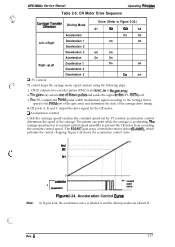
... 2-24, the acceleration curve is accelerating. SFlet , . SPl Note: o MYxleratiofl B r decderaiion 2 Figure 2-24. Rev. CR Motor Drive Sequence Operating Pdncipbs Carria#~T~;sfer Driving Mode Driver (Refer to prevent the CR motor from exceeding the constant control speed. 'l'he E05A87 gate array controls the motor.... 4. CN1O outputs two encoder pulses (ENC-A and ENC-B) to the PWM port of the gate array and determines the duty of the carriage. The printer can print while the carriage is labeled A and the driving modes are labeled B. DFX-5000+ Service Manual Table 2-5. A 2-27
... 2-24, the acceleration curve is accelerating. SFlet , . SPl Note: o MYxleratiofl B r decderaiion 2 Figure 2-24. Rev. CR Motor Drive Sequence Operating Pdncipbs Carria#~T~;sfer Driving Mode Driver (Refer to prevent the CR motor from exceeding the constant control speed. 'l'he E05A87 gate array controls the motor.... 4. CN1O outputs two encoder pulses (ENC-A and ENC-B) to the PWM port of the gate array and determines the duty of the carriage. The printer can print while the carriage is labeled A and the driving modes are labeled B. DFX-5000+ Service Manual Table 2-5. A 2-27
Service Manual
Page 67
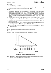
... to accelerate. 2. It causes the carriage to the next sequence (SP1 - SP2 1. Pulse width modulation (PWM) determines each section, the carriage motor driver is turned on part of the time and off part of the time. 2. Note: : 1 Deceieratbn 2 B 4Dacalf%on the duty data, and ... with the encoder signal, when the carriage speed reaches SP1, it uses Deceleration driving mode 2. (Refer to Table 2-5.) 3. SP1 - The DFX-5000+ printer has a table programmed into ten sections, plus Dutymin. For each section number. During this time the control circuit measures time periods using the ...
... to accelerate. 2. It causes the carriage to the next sequence (SP1 - SP2 1. Pulse width modulation (PWM) determines each section, the carriage motor driver is turned on part of the time and off part of the time. 2. Note: : 1 Deceieratbn 2 B 4Dacalf%on the duty data, and ... with the encoder signal, when the carriage speed reaches SP1, it uses Deceleration driving mode 2. (Refer to Table 2-5.) 3. SP1 - The DFX-5000+ printer has a table programmed into ten sections, plus Dutymin. For each section number. During this time the control circuit measures time periods using the ...

Service Manual
Page 68
... arcuit measures time periods usrng the encoder signal. A 2-29 For each section number. Speedo 1. Ct Measurement sequence Because printer mechanisms differ, the acceleration and deceleration curves also diftkr. 'Ihe measurement sequence control adjusts for the eight most recent sections.... is the inverse-continuity break method. 2. Pulse width modulation (PWM) determines each section, the carriage motor driver is determined by the data in the printer mechanism. This control method is the largest, and Dutytil represents the minimum duty data for individual variations in ...
... arcuit measures time periods usrng the encoder signal. A 2-29 For each section number. Speedo 1. Ct Measurement sequence Because printer mechanisms differ, the acceleration and deceleration curves also diftkr. 'Ihe measurement sequence control adjusts for the eight most recent sections.... is the inverse-continuity break method. 2. Pulse width modulation (PWM) determines each section, the carriage motor driver is determined by the data in the printer mechanism. This control method is the largest, and Dutytil represents the minimum duty data for individual variations in ...
Service Manual
Page 69
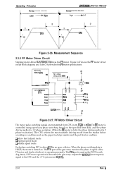
...SLA7026 (ICI 1) -.J Operating Principles Carrige transfer direction t3 1 SP2 DEX-5000+ Service Manual Carrige transfer direction [ Right ~ Left t3 1 SP2 Figure 2-26. Figure 2-27 shows the PF motor driver circuit block diagram, and Table 2-6 provides the PF motor specifications. Measurement Sequence... 2.3.5 PF Motor Driver Circuit Stepping motor driver SLA7026 (IC1l) drives the PF motor. IN-B -B PF D 1= ...
...SLA7026 (ICI 1) -.J Operating Principles Carrige transfer direction t3 1 SP2 DEX-5000+ Service Manual Carrige transfer direction [ Right ~ Left t3 1 SP2 Figure 2-26. Figure 2-27 shows the PF motor driver circuit block diagram, and Table 2-6 provides the PF motor specifications. Measurement Sequence... 2.3.5 PF Motor Driver Circuit Stepping motor driver SLA7026 (IC1l) drives the PF motor. IN-B -B PF D 1= ...

Service Manual
Page 70
... method Table 2-7. RF Motor Specifications I i I I Description I I 4-phase, 46-poie, PM pulse motor I 35 VDC * 6% (apptied to the driver circuit) 1 I Internal coil resistance I 2.65 f2 +0.32 Llperphaseat 25°C (77°F) I Frequency 4274 pps~ (normal mode, constant driving): 9.9 ... TMP96C141 (lCl) PG1O ® PG 11 " ® PG12 ® , PG 13 + ~ PNP Transistor x4 CN; e ,.. ,. ("J DEX-5000+ Sarvice Manual Table 2-6. The control circuit perlbrms open-loop phase switching control according to PG13 output the motor phase switching signals.
... method Table 2-7. RF Motor Specifications I i I I Description I I 4-phase, 46-poie, PM pulse motor I 35 VDC * 6% (apptied to the driver circuit) 1 I Internal coil resistance I 2.65 f2 +0.32 Llperphaseat 25°C (77°F) I Frequency 4274 pps~ (normal mode, constant driving): 9.9 ... TMP96C141 (lCl) PG1O ® PG 11 " ® PG12 ® , PG 13 + ~ PNP Transistor x4 CN; e ,.. ,. ("J DEX-5000+ Sarvice Manual Table 2-6. The control circuit perlbrms open-loop phase switching control according to PG13 output the motor phase switching signals.


