

Installation Instructions
Page 1
Installation Instructions Electrolux Front-Load Gas a Electric Dryer E Electrolux 1)701820) A 10e0i I
Installation Instructions Electrolux Front-Load Gas a Electric Dryer E Electrolux 1)701820) A 10e0i I
Installation Instructions
Page 2
Wo Mow your proauct with Electrolux ennano our aceny to serve you. Ges dryer 11 Electrical connection - Elect& dryer (3-wIre call... 12 Electrical connection - Bectric dryer (4-wirecacq...13 Gee oarnectian 14 Water connection (Steam Model only) 15-16 General installation 17 Performing installs:bar cycle is Resenting &cc 1943 Options 24 • Access:ties 44 • Replacement parts...
Wo Mow your proauct with Electrolux ennano our aceny to serve you. Ges dryer 11 Electrical connection - Elect& dryer (3-wIre call... 12 Electrical connection - Bectric dryer (4-wirecacq...13 Gee oarnectian 14 Water connection (Steam Model only) 15-16 General installation 17 Performing installs:bar cycle is Resenting &cc 1943 Options 24 • Access:ties 44 • Replacement parts...
Installation Instructions
Page 3
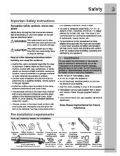
...tins manual rrust be Madroimpe (deasio deer) cling (gm dryer) (gan dryer) (not awl tape) Read all other appliance. ANSI/ NFPA 70, or in Canada, the Canadian electrical code C22.1 part 1. • The gas senAce tothe dryer must conform with nags, bedspreads, or pasha sheets can ...4 belt rigd Mad C. tions tnat may occur. This dryer Is not recommended for canny:row applications such as WARNING this symbol alerts you to the rrenutacturers instructions and boat codes. • The electrical seiviceto the dryer must be applied wren installing. tion of the following hstructIons...
...tins manual rrust be Madroimpe (deasio deer) cling (gm dryer) (gan dryer) (not awl tape) Read all other appliance. ANSI/ NFPA 70, or in Canada, the Canadian electrical code C22.1 part 1. • The gas senAce tothe dryer must conform with nags, bedspreads, or pasha sheets can ...4 belt rigd Mad C. tions tnat may occur. This dryer Is not recommended for canny:row applications such as WARNING this symbol alerts you to the rrenutacturers instructions and boat codes. • The electrical seiviceto the dryer must be applied wren installing. tion of the following hstructIons...
Installation Instructions
Page 4
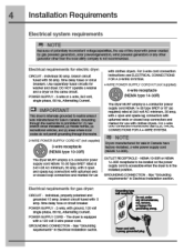
...3O type SRDT or ST (as requited) rated at 240 vort AC minimum, 3O amp, with 3-prong grounded piug IM NOTE Dryers manufactured ror sale in Electrical installation section. Cee "Grounding requirements' in Canada nave factory-instance, a-wre power Supply CON] (NEMA 1,1-3OR). Individua . ... Is prOnIDIted for US) with cbthes Myers For 3-wire corn connection Instructions see ELECTRICAL CONNECTIONS FOR A 4-WIRE SYSTEM. branch circuit fused with upturned ends or coed loop connectors and ramrod for electric dryer. Poorer coin with 3 open end spade lug connectors with 3O amp. popery...
...3O type SRDT or ST (as requited) rated at 240 vort AC minimum, 3O amp, with 3-prong grounded piug IM NOTE Dryers manufactured ror sale in Electrical installation section. Cee "Grounding requirements' in Canada nave factory-instance, a-wre power Supply CON] (NEMA 1,1-3OR). Individua . ... Is prOnIDIted for US) with cbthes Myers For 3-wire corn connection Instructions see ELECTRICAL CONNECTIONS FOR A 4-WIRE SYSTEM. branch circuit fused with upturned ends or coed loop connectors and ramrod for electric dryer. Poorer coin with 3 open end spade lug connectors with 3O amp. popery...

Installation Instructions
Page 5
neAlble metal tubing may be 1/2 Inch (1.27 cm) pipe. 3 it with a rigid or sell-rigid metal... is in tne absence of the gas supply piping system al test pressures equal to instal ing dryer duct. U. When the dryer stop, the dampers automatically CMG to collapse. Flexible venting matenais are specific requirements for gas supply... be Isolatec 'nom the gas supply piping system during any lint prior to or lessthan 1/2 pslg (3.45 kPa). The dryer MUST be disconnected tI0M the gas supply piping system curing any other obstruction. ,1\ WARNING FIRE HAZARD 1 Failure 10 follow mese...
neAlble metal tubing may be 1/2 Inch (1.27 cm) pipe. 3 it with a rigid or sell-rigid metal... is in tne absence of the gas supply piping system al test pressures equal to instal ing dryer duct. U. When the dryer stop, the dampers automatically CMG to collapse. Flexible venting matenais are specific requirements for gas supply... be Isolatec 'nom the gas supply piping system during any lint prior to or lessthan 1/2 pslg (3.45 kPa). The dryer MUST be disconnected tI0M the gas supply piping system curing any other obstruction. ,1\ WARNING FIRE HAZARD 1 Failure 10 follow mese...

Installation Instructions
Page 6
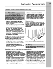
...HAZARD Exceeding me rengtnot duct pipe or number ulUvwS ailNVuV le lie "MAXIMUM LENGTH" charts can become caught In me screen. If Tie dryer is ne descncod in contact with tie flow of 4' O0.2errosemmiold meta oist 5 VENT HOOD TYPE twat (102a11) ""...i [0 tamed ... .34m) MAXIMUM LENGTH 2 of air. 6 Installation Requirements Exhaust system requirements, continued WARNING FIRE HAZARD A clothes dryer mug be expelled into ti laundry area. A Clothes dryer produces combustible lint. some fine lint will be exhausted outdoors. WARNING FIRE HAZARD • Do not allow corntustiDie ...
...HAZARD Exceeding me rengtnot duct pipe or number ulUvwS ailNVuV le lie "MAXIMUM LENGTH" charts can become caught In me screen. If Tie dryer is ne descncod in contact with tie flow of 4' O0.2errosemmiold meta oist 5 VENT HOOD TYPE twat (102a11) ""...i [0 tamed ... .34m) MAXIMUM LENGTH 2 of air. 6 Installation Requirements Exhaust system requirements, continued WARNING FIRE HAZARD A clothes dryer mug be expelled into ti laundry area. A Clothes dryer produces combustible lint. some fine lint will be exhausted outdoors. WARNING FIRE HAZARD • Do not allow corntustiDie ...
Installation Instructions
Page 7
...cilmping c$ the exhaust system will Cause an increase in 0lameter with the teminatlon securely fastened to air fluff (cool awn) and start the dryer 3 Read tne measurement on Me nod page. • Running the exhaust system through an uninsulated area may cause conaensation and faster aocumulation... if the system bath pressure Is less tnan 1.0 inch of the exhaust system *accEptaltie. certain extenuating circumstances cpula affect the performance of the dryer. • Only tne ngla metal duct won( should check the exhaust system and vent hood for Moble Home Construction and Safety, Tine 24...
...cilmping c$ the exhaust system will Cause an increase in 0lameter with the teminatlon securely fastened to air fluff (cool awn) and start the dryer 3 Read tne measurement on Me nod page. • Running the exhaust system through an uninsulated area may cause conaensation and faster aocumulation... if the system bath pressure Is less tnan 1.0 inch of the exhaust system *accEptaltie. certain extenuating circumstances cpula affect the performance of the dryer. • Only tne ngla metal duct won( should check the exhaust system and vent hood for Moble Home Construction and Safety, Tine 24...
Installation Instructions
Page 8
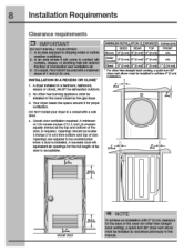
...come in an area onto n will obstrut the now of comb.etion and ventuabon air. 3. Openings should be enausted otitdocrs. 2. crapes. On carpet. A dryer installed In a bedroom, bathroom, recess or closet. DO NOT install your flyer In a closetwith a sollc door. 4. Pal " pa)$ 7 7$17^4 11... dcor ventilation required: A minimum ot 120 square inches (774.2 cm") of tle door Is acceptable. a quick-tum SO° dryer vent elbow must be installed to be Installed In the same closet as desalbed previcusly in an area expouol tochippingwater or outslile weenier condition....
...come in an area onto n will obstrut the now of comb.etion and ventuabon air. 3. Openings should be enausted otitdocrs. 2. crapes. On carpet. A dryer installed In a bedroom, bathroom, recess or closet. DO NOT install your flyer In a closetwith a sollc door. 4. Pal " pa)$ 7 7$17^4 11... dcor ventilation required: A minimum ot 120 square inches (774.2 cm") of tle door Is acceptable. a quick-tum SO° dryer vent elbow must be installed to be Installed In the same closet as desalbed previcusly in an area expouol tochippingwater or outslile weenier condition....

Installation Instructions
Page 9
ernonicts.dpr emonlitot bingsvid nap. Installation Requirements 9 AIM Installed dryer dimensions ferroideiny to dampen door ea Mel as dear (Oder, O ter assn gest IleceNns J Oar (110.Sal sr, IsId.la tv-wft re".7 dive navitid *...
ernonicts.dpr emonlitot bingsvid nap. Installation Requirements 9 AIM Installed dryer dimensions ferroideiny to dampen door ea Mel as dear (Oder, O ter assn gest IleceNns J Oar (110.Sal sr, IsId.la tv-wft re".7 dive navitid *...
Installation Instructions
Page 10
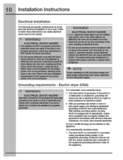
...plug you've installed on 240 volt power supply. rule Wein roar te not attached. Grounding requirements - Electric dryer (USA) FA\ WARNING ELECTRICAL SHOCK HAZARD improper ccnnection of least resistance forelectncal current. 2. copper wired receptacle tnat is properly grounae0. the... to De qurcnased. For a grounded. For a permanently connected dryer 1. Electrical shock can cause electrical snorts. e Do not use an aiurrinum wired receptacle with this manual tor proper grounding. cord-ponnectea dryer 1. resulting in crectncal shock. • Do not use an...
...plug you've installed on 240 volt power supply. rule Wein roar te not attached. Grounding requirements - Electric dryer (USA) FA\ WARNING ELECTRICAL SHOCK HAZARD improper ccnnection of least resistance forelectncal current. 2. copper wired receptacle tnat is properly grounae0. the... to De qurcnased. For a grounded. For a permanently connected dryer 1. Electrical shock can cause electrical snorts. e Do not use an aiurrinum wired receptacle with this manual tor proper grounding. cord-ponnectea dryer 1. resulting in crectncal shock. • Do not use an...
Installation Instructions
Page 11
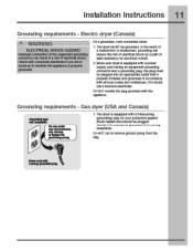
...in accoroance with a power supply cora having an equinmerrt-grounaing conauctor ana a grounaing plug, the plug must be grounded. Electrb dryer (Canada) A\ WARNING ELECTRICAL SHCCK HAZARD improper ccnnection of trio equipment grounding conductor can Neuit in a rm< 07 oicetnoai snocic Check vita a ricenson electrician if... ground prong from the pitg. Power coed with the ap)liance. DO NOT moony the plug provned with 3-Pron9 ~dad ISO Gas dryer (USA and Canada) a,fii LQantz.) grameoll Pone. 1. Since your protection against shock nazaro ana should to whether the apcuance Is properly...
...in accoroance with a power supply cora having an equinmerrt-grounaing conauctor ana a grounaing plug, the plug must be grounded. Electrb dryer (Canada) A\ WARNING ELECTRICAL SHCCK HAZARD improper ccnnection of trio equipment grounding conductor can Neuit in a rm< 07 oicetnoai snocic Check vita a ricenson electrician if... ground prong from the pitg. Power coed with the ap)liance. DO NOT moony the plug provned with 3-Pron9 ~dad ISO Gas dryer (USA and Canada) a,fii LQantz.) grameoll Pone. 1. Since your protection against shock nazaro ana should to whether the apcuance Is properly...
Installation Instructions
Page 12
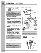
12 Installation Instructions Electrical connection (non-Canada) - 3 wire cord 3-wire receptacle %00 (NEMA type 10-30R) /?\ WARNING ELECTRICAL SHOCK HAZARD Failure to
12 Installation Instructions Electrical connection (non-Canada) - 3 wire cord 3-wire receptacle %00 (NEMA type 10-30R) /?\ WARNING ELECTRICAL SHOCK HAZARD Failure to

Installation Instructions
Page 13
...the strain relied snould be retrieved in the power cord entry hole below the access panel. Tighten the screw securcly. 7 Move the internal dryer Maness ground (BLACK) wire to the terminal dock and attach It along With tne neutral (WHITE) power cord wire conductor to tne center... raiis during corn installation, It 3n be loosely In place. 4 Thread an UNPLUGGED UL-approved, 30 amp. Tighten both screws %CUrely. ?\ WARNING ELECTRICAL SHCCK HAZARD Do not make a snarp bend or crimp wiring/ conauctor at connedions. 9 FOIray manufacturer's gtklellneS tor WMly securing tie strain relief ana power...
...the strain relied snould be retrieved in the power cord entry hole below the access panel. Tighten the screw securcly. 7 Move the internal dryer Maness ground (BLACK) wire to the terminal dock and attach It along With tne neutral (WHITE) power cord wire conductor to tne center... raiis during corn installation, It 3n be loosely In place. 4 Thread an UNPLUGGED UL-approved, 30 amp. Tighten both screws %CUrely. ?\ WARNING ELECTRICAL SHCCK HAZARD Do not make a snarp bend or crimp wiring/ conauctor at connedions. 9 FOIray manufacturer's gtklellneS tor WMly securing tie strain relief ana power...
Installation Instructions
Page 14
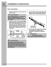
Remove the snipping cap from gas pipe at the near ot the dryer. MI IMPORTANT DO NOT connect tna 14 Installation Instructions Gas connection 1.
Remove the snipping cap from gas pipe at the near ot the dryer. MI IMPORTANT DO NOT connect tna 14 Installation Instructions Gas connection 1.

Installation Instructions
Page 16
16 Installation Instructions Water connection, con't (Steam Model only) 1. re NOTE Ityou wereabletoInstalthe"r connector direct to the COLD water supply, please slUp to the "r connelor and snug it by hand; of the dryer and snug it by hand then tighten It another 2/3 turn with pliers. 4. S. ...WATER NISICN OFMER Awe ,%\ °OLDWATER SISAY ROSE TO WASHER than tighten It another 2'3 turn with pliers. lighten each correction ot the dryer Inlet hose another 2/3 turn with pliers. 5. then tight an Il miotlisi wlha pima. Thread the wr connector to tho Crass wator Inlot...
16 Installation Instructions Water connection, con't (Steam Model only) 1. re NOTE Ityou wereabletoInstalthe"r connector direct to the COLD water supply, please slUp to the "r connelor and snug it by hand; of the dryer and snug it by hand then tighten It another 2/3 turn with pliers. 4. S. ...WATER NISICN OFMER Awe ,%\ °OLDWATER SISAY ROSE TO WASHER than tighten It another 2'3 turn with pliers. lighten each correction ot the dryer Inlet hose another 2/3 turn with pliers. 5. then tight an Il miotlisi wlha pima. Thread the wr connector to tho Crass wator Inlot...
Installation Instructions
Page 17
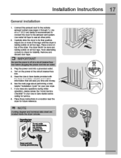
... are located inside the dryercc:rude. r Domtunder ;Awls** 14/ . 9muleV/Perill L %CO Place a level on all otner joints. 2 Canefully slide the dryer to the outside exhaust system (see pages 5 through 7). The diyer MUST be level and resting solidly on the power at thecituft breaker/fuse box. 5 Read... the Use & Care Guide provided with the dryer. Remove and discern door tape. Use of the dryer. use motet fog tape to seal all tourlegs. It contains valLable and helpful tot information that will save you lime...
... are located inside the dryercc:rude. r Domtunder ;Awls** 14/ . 9muleV/Perill L %CO Place a level on all otner joints. 2 Canefully slide the dryer to the outside exhaust system (see pages 5 through 7). The diyer MUST be level and resting solidly on the power at thecituft breaker/fuse box. 5 Read... the Use & Care Guide provided with the dryer. Remove and discern door tape. Use of the dryer. use motet fog tape to seal all tourlegs. It contains valLable and helpful tot information that will save you lime...
Installation Instructions
Page 18
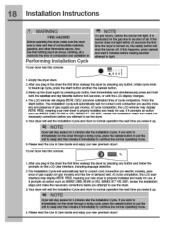
... Cyclewill automatically test to touch up . Ai• 0 1.Empty the dryer arum. 2.Atter you plug in the dryer tne first time: wake m the dryer Dy pressing any button, rotate cycle knob to ' correct cord connection (at electric MCCIGIS), presence ot gas supply (on . The installation Cycle will display ...awake Ta 3 minutes alter the installation Cycles t pu wish to sleep and then rewalm it Performing Installation Cycle If your dryer has this console: r, NOTE on electric mod- If pu wish to immecilwely run tre cry& through a crying cycle, press the cancel Dutton to put tne...
... Cyclewill automatically test to touch up . Ai• 0 1.Empty the dryer arum. 2.Atter you plug in the dryer tne first time: wake m the dryer Dy pressing any button, rotate cycle knob to ' correct cord connection (at electric MCCIGIS), presence ot gas supply (on . The installation Cycle will display ...awake Ta 3 minutes alter the installation Cycles t pu wish to sleep and then rewalm it Performing Installation Cycle If your dryer has this console: r, NOTE on electric mod- If pu wish to immecilwely run tre cry& through a crying cycle, press the cancel Dutton to put tne...
Installation Instructions
Page 19
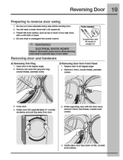
... course-thread, panheed screw. Removing door and hardware Tools healed: Scrwedrivers with a soft cloth or towel. 4 Be sure dryer Is unplucged from power source) th WARNING ELECTRICAL SHOCK HkZARD Failureto disconnect power source Iatom savicIng could result in persona injury or eve death. B)Removing Door from dear. 3...before reversing door 2 You will need a screw driver with a t2 square bit. 3 Protect flat woik surface, such as top of dryer or11)or near dryer, with square straight bit A) Removing Trim Ring 1 Open door to 90 degree angle. 2 Remove 2 shdrt, coursathread, panhead screws.
... course-thread, panheed screw. Removing door and hardware Tools healed: Scrwedrivers with a soft cloth or towel. 4 Be sure dryer Is unplucged from power source) th WARNING ELECTRICAL SHOCK HkZARD Failureto disconnect power source Iatom savicIng could result in persona injury or eve death. B)Removing Door from dear. 3...before reversing door 2 You will need a screw driver with a t2 square bit. 3 Protect flat woik surface, such as top of dryer or11)or near dryer, with square straight bit A) Removing Trim Ring 1 Open door to 90 degree angle. 2 Remove 2 shdrt, coursathread, panhead screws.
Installation Instructions
Page 20
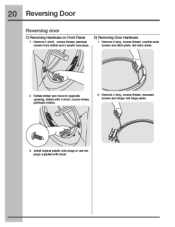
counter-surd( screws and latch plate. recessed screws and hinge. Set hinge aside. 3 Install nal plastic hole plugs or use new plugs suppliedwith dryer. Set latch aside. 2 Rotate striker and movetooppsite opening. couise-trireai, pannead scams. 2 Remove 4 Iamb course-thread. Iy D) Removing Door Hardware 1 Remove 2 Iamb course-thread. 20 Reversing Door Reversing door C) Reversing Hardware on Front Panel 1 Remove 2 slut, course-thread, panhead screws trom sinker and 2 plastic hole plugs. Mt:at-Iwith 2 short.
counter-surd( screws and latch plate. recessed screws and hinge. Set hinge aside. 3 Install nal plastic hole plugs or use new plugs suppliedwith dryer. Set latch aside. 2 Rotate striker and movetooppsite opening. couise-trireai, pannead scams. 2 Remove 4 Iamb course-thread. Iy D) Removing Door Hardware 1 Remove 2 Iamb course-thread. 20 Reversing Door Reversing door C) Reversing Hardware on Front Panel 1 Remove 2 slut, course-thread, panhead screws trom sinker and 2 plastic hole plugs. Mt:at-Iwith 2 short.
Installation Instructions
Page 23
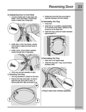
... ciccievise approximately W. 2 Install other 2 short. Opening In ring should be on the tack 2 Remove trim ring cove' plate. lb a remove plate titim rigrr. Plug in dryer and cant nue operation. M Reinstalling Trim Ring 1 Close door. 2 orient trim 30 12 pcobai b oppicalmutely W to ao degreemg*. 2 Install trim plug with 1 icng, course-thread...
... ciccievise approximately W. 2 Install other 2 short. Opening In ring should be on the tack 2 Remove trim ring cove' plate. lb a remove plate titim rigrr. Plug in dryer and cant nue operation. M Reinstalling Trim Ring 1 Close door. 2 orient trim 30 12 pcobai b oppicalmutely W to ao degreemg*. 2 Install trim plug with 1 icng, course-thread...


