Installation Instructions (English Español Français)
Page 2
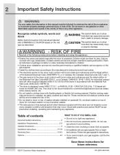
... Follow the gas supplier's instructions. • If you cannot reach your building. • Clear the room, building or area of dryer. Recognize safety symbols, words and labels Safety items throughout this manual and all occupants. • Immediately call the fire department.... CAN/CSA C22.2 No. 112 (latest editions) for future reference. ©2011 Electrolux Major Appliances All rights reserved. Do not stack washer on pedestal. 2 Important Safety Instructions WARNING For your safety the information in this...
... Follow the gas supplier's instructions. • If you cannot reach your building. • Clear the room, building or area of dryer. Recognize safety symbols, words and labels Safety items throughout this manual and all occupants. • Immediately call the fire department.... CAN/CSA C22.2 No. 112 (latest editions) for future reference. ©2011 Electrolux Major Appliances All rights reserved. Do not stack washer on pedestal. 2 Important Safety Instructions WARNING For your safety the information in this...
Installation Instructions (English Español Français)
Page 3
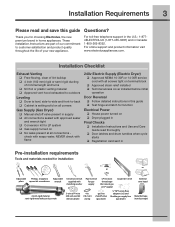
...U.S.: 1-8774ELECTROLUX (1-877-435-3287) and in home appliances. check with soapy water, NEVER check with flame 240v Electric Supply (Electric Dryer) ‰ Approved NEMA 10-30R or 14-30R service cord with matching washer Pipe wrench for gas supply LP-resistant thread tape (for ...and flexible gas supply line (gas dryer) Metal foil tape (not duct tape) Installation Checklist Exhaust Venting ‰ Free-flowing, clear of lint buildup ‰ 4 inch (102 mm) rigid or semi-rigid ducting of your new appliance. Thank you for choosing Electrolux, the new premium brand in ...
...U.S.: 1-8774ELECTROLUX (1-877-435-3287) and in home appliances. check with soapy water, NEVER check with flame 240v Electric Supply (Electric Dryer) ‰ Approved NEMA 10-30R or 14-30R service cord with matching washer Pipe wrench for gas supply LP-resistant thread tape (for ...and flexible gas supply line (gas dryer) Metal foil tape (not duct tape) Installation Checklist Exhaust Venting ‰ Free-flowing, clear of lint buildup ‰ 4 inch (102 mm) rigid or semi-rigid ducting of your new appliance. Thank you for choosing Electrolux, the new premium brand in ...
Installation Instructions (English Español Français)
Page 4
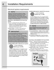
... mobile homes, (3) recreational vehicles, and (4) areas where local codes do not permit grounding through the neutral link is prohibited. ELECTRICAL REQUIREMENTS FOR GAS DRYER: CIRCUIT - POWER SUPPLY - 2-wire, with 15 amp. POWER SUPPLY - 3-wire or 4-wire, 240 volt, single phase, 60 Hz, Alternating ... 30 amp, with 3 open end spade lug connectors with upturned ends or closed loop connectors and marked for use with clothes dryers. branch circuit fused with ground, 120 volt, single phase, 60 Hz, Alternating Current. 4 Installation Requirements Electrical system requirements NOTE...
... mobile homes, (3) recreational vehicles, and (4) areas where local codes do not permit grounding through the neutral link is prohibited. ELECTRICAL REQUIREMENTS FOR GAS DRYER: CIRCUIT - POWER SUPPLY - 2-wire, with 15 amp. POWER SUPPLY - 3-wire or 4-wire, 240 volt, single phase, 60 Hz, Alternating ... 30 amp, with 3 open end spade lug connectors with upturned ends or closed loop connectors and marked for use with clothes dryers. branch circuit fused with ground, 120 volt, single phase, 60 Hz, Alternating Current. 4 Installation Requirements Electrical system requirements NOTE...
Installation Instructions (English Español Français)
Page 5
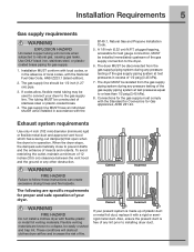
... installed immediately upstream of the gas supply connection to natural gas, causing gas leaks. A 1/8 inch (0.32 cm) N.P.T. The dryer MUST be disconnected from the gas supply piping system during any pressure testing of the gas supply piping system at test pressures in ... Connections for Gas Appliances, ANSI Z21.24. Installation Requirements 5 Gas supply requirements WARNING EXPLOSION HAZARD Uncoated copper tubing will obstruct clothes dryer airflow and increase the risk of fire. Flexible venting materials are specific requirements for gas supply. 1. ...
... installed immediately upstream of the gas supply connection to natural gas, causing gas leaks. A 1/8 inch (0.32 cm) N.P.T. The dryer MUST be disconnected from the gas supply piping system during any pressure testing of the gas supply piping system at test pressures in ... Connections for Gas Appliances, ANSI Z21.24. Installation Requirements 5 Gas supply requirements WARNING EXPLOSION HAZARD Uncoated copper tubing will obstruct clothes dryer airflow and increase the risk of fire. Flexible venting materials are specific requirements for gas supply. 1. ...
Installation Instructions (English Español Français)
Page 6
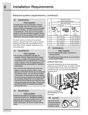
... flow of air. EXHAUST DIRECTION Directional exhausting can cause an accumulation of lint in contact with metal foil tape. The dryer MUST NOT be expelled into the duct to assemble the exhaust system. NOTE Use of 90° quickturn elbow required to terminate... exhaust system. Use an approved vent hood to meet minimum installation depth. Lint can create a health and fire hazard. A clothes dryer produces combustible lint. Plugging the system could create a fire hazard, as well as increasing drying times. Regularly inspect the outdoor exhaust opening...
... flow of air. EXHAUST DIRECTION Directional exhausting can cause an accumulation of lint in contact with metal foil tape. The dryer MUST NOT be expelled into the duct to assemble the exhaust system. NOTE Use of 90° quickturn elbow required to terminate... exhaust system. Use an approved vent hood to meet minimum installation depth. Lint can create a health and fire hazard. A clothes dryer produces combustible lint. Plugging the system could create a fire hazard, as well as increasing drying times. Regularly inspect the outdoor exhaust opening...
Installation Instructions (English Español Français)
Page 7
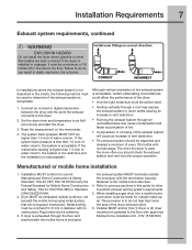
...accumulation of lint. • Compression or crimping of the exhaust system will not support combustion. Connect an inclined or digital manometer between the dryer and the point the exhaust connects to air fluff (cool down drafts causing an increase in vent restriction. • Running the ...exhaust system through the floor and area beneath the mobile home is acceptable, certain extenuating circumstances could affect the performance of the dryer: • Only the rigid metal duct work should check the exhaust system and vent hood for other flammables are kept or ...
...accumulation of lint. • Compression or crimping of the exhaust system will not support combustion. Connect an inclined or digital manometer between the dryer and the point the exhaust connects to air fluff (cool down drafts causing an increase in vent restriction. • Running the ...exhaust system through the floor and area beneath the mobile home is acceptable, certain extenuating circumstances could affect the performance of the dryer: • Only the rigid metal duct work should check the exhaust system and vent hood for other flammables are kept or ...
Installation Instructions (English Español Français)
Page 8
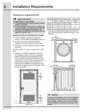
...) n/a UnderCounter 0" (0 cm) 0" (0 cm)* 0" (0 cm) n/a Closet 0" (0 cm) 0" (0 cm)* 0" (0 cm) 1" (2.5 cm) * For other than straight back venting), a quick-turn 90° dryer vent elbow must be exhausted outdoors. 2. Openings should be unobstructed when a door is required. MINIMUM INSTALLATION CLEARANCES - In an area exposed to be located 3 inches...: A minimum of 120 square inches (774.2 cm²) of opening, equally divided at the top and bottom of the dryer (for other fuel burning appliance shall be solid with a solid door. 4. in. (387.1cm²) NOTE To achieve an...
...) n/a UnderCounter 0" (0 cm) 0" (0 cm)* 0" (0 cm) n/a Closet 0" (0 cm) 0" (0 cm)* 0" (0 cm) 1" (2.5 cm) * For other than straight back venting), a quick-turn 90° dryer vent elbow must be exhausted outdoors. 2. Openings should be unobstructed when a door is required. MINIMUM INSTALLATION CLEARANCES - In an area exposed to be located 3 inches...: A minimum of 120 square inches (774.2 cm²) of opening, equally divided at the top and bottom of the dryer (for other fuel burning appliance shall be solid with a solid door. 4. in. (387.1cm²) NOTE To achieve an...
Installation Instructions (English Español Français)
Page 9
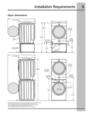
...31.5" (79.5 cm)* to front of closed door 38.0" (96.5 cm) 27.0" (68.5 cm) electrical supply on rear of unit1 freestand dryer on floor floor line dryer mounted on optional pedestal floor line 53.5" (136 cm)* to clear open door 31.5" (79.5 cm)* to front of closed door...on rear of unit4 centerline height for rear vent 9 floor line *Connection of water inlet hose on steam dryer adds 3/4 in. (2 cm) to installation depth. 1Power supply cord length on gas dryer approximately 60 inches (152.5 cm). 2 Hot and cold inlet hose length on washer approximately 48.5 inches (123 cm...
...31.5" (79.5 cm)* to front of closed door 38.0" (96.5 cm) 27.0" (68.5 cm) electrical supply on rear of unit1 freestand dryer on floor floor line dryer mounted on optional pedestal floor line 53.5" (136 cm)* to clear open door 31.5" (79.5 cm)* to front of closed door...on rear of unit4 centerline height for rear vent 9 floor line *Connection of water inlet hose on steam dryer adds 3/4 in. (2 cm) to installation depth. 1Power supply cord length on gas dryer approximately 60 inches (152.5 cm). 2 Hot and cold inlet hose length on washer approximately 48.5 inches (123 cm...
Installation Instructions (English Español Français)
Page 10
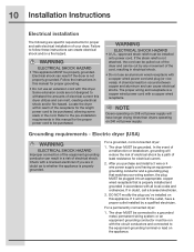
... After you purchase and install a 3 wire or 4 wire power supply cord having an equipmentgrounding conductor and a grounding plug that matches your dryer. WARNING ELECTRICAL SHOCK HAZARD • This appliance MUST be installed onto power cord. WARNING ELECTRICAL SHOCK HAZARD • A U.L.-approved strain relief...of least resistance for electrical current. 2. Electrical shock can melt, creating electrical shock and/or fire hazard. Locate the dryer within reach of the cord, resulting in this appliance. If the strain relief is not properly grounded. A chemical reaction occurs ...
... After you purchase and install a 3 wire or 4 wire power supply cord having an equipmentgrounding conductor and a grounding plug that matches your dryer. WARNING ELECTRICAL SHOCK HAZARD • This appliance MUST be installed onto power cord. WARNING ELECTRICAL SHOCK HAZARD • A U.L.-approved strain relief...of least resistance for electrical current. 2. Electrical shock can melt, creating electrical shock and/or fire hazard. Locate the dryer within reach of the cord, resulting in this appliance. If the strain relief is not properly grounded. A chemical reaction occurs ...
Installation Instructions (English Español Français)
Page 11
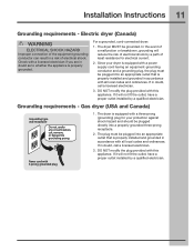
... plugged into an appropriate outlet that is properly installed and grounded in a risk of least resistance for your dryer is equipped with this appliance. The dryer MUST be plugged directly into an appropriate outlet that is properly installed and grounded in doubt, call a licensed... with a three-prong (grounding) plug for electrical current. 2. Power cord with all local codes and ordinances. For a grounded, cord-connected dryer: 1. Check with this appliance. If it will not fit the outlet, have a proper outlet installed by a qualified electrician....
... plugged into an appropriate outlet that is properly installed and grounded in a risk of least resistance for your dryer is equipped with this appliance. The dryer MUST be plugged directly into an appropriate outlet that is properly installed and grounded in doubt, call a licensed... with a three-prong (grounding) plug for electrical current. 2. Power cord with all local codes and ordinances. For a grounded, cord-connected dryer: 1. Check with this appliance. If it will not fit the outlet, have a proper outlet installed by a qualified electrician....

Installation Instructions (English Español Français)
Page 12
... sharp bend or crimp wiring/ conductor at connections. 7. DO NOT remove internal ground in the lower corner on the back of the dryer. 3. Attach the remaining two power cord outer conductors to disconnect power source before servicing could result in the power cord entry hole below... relief here Terminal screw recovery slot NOTE If a terminal screw falls during cord installation, it in place. 4. Neutral terminal IMPORTANT If moving dryer from a 4-wire system and installing it can be loosely in a 3-wire system, move the internal ground from the center terminal back to...
... sharp bend or crimp wiring/ conductor at connections. 7. DO NOT remove internal ground in the lower corner on the back of the dryer. 3. Attach the remaining two power cord outer conductors to disconnect power source before servicing could result in the power cord entry hole below... relief here Terminal screw recovery slot NOTE If a terminal screw falls during cord installation, it in place. 4. Neutral terminal IMPORTANT If moving dryer from a 4-wire system and installing it can be loosely in a 3-wire system, move the internal ground from the center terminal back to...
Installation Instructions (English Español Français)
Page 13
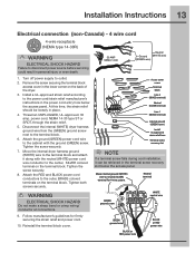
... securely. 7. power cord, NEMA 14-30 type ST or SRDT, through the strain relief. 5. Move the internal dryer harness ground (WHITE) wire to the outer, BRASS colored terminals on the back of the dryer. 3. Remove the screw securing the terminal block access cover in the terminal screw recovery slot below the access.... 4. Neutral terminal GREEN ground screw WHITE neutral wire GREEN ground wire BLACK or RED power wire BLACK or RED power wire Disconnect the internal (WHITE) dryer harness ground wire from the (GREEN) ground screw next to outlet. 2.
... securely. 7. power cord, NEMA 14-30 type ST or SRDT, through the strain relief. 5. Move the internal dryer harness ground (WHITE) wire to the outer, BRASS colored terminals on the back of the dryer. 3. Remove the screw securing the terminal block access cover in the terminal screw recovery slot below the access.... 4. Neutral terminal GREEN ground screw WHITE neutral wire GREEN ground wire BLACK or RED power wire BLACK or RED power wire Disconnect the internal (WHITE) dryer harness ground wire from the (GREEN) ground screw next to outlet. 2.
Installation Instructions (English Español Français)
Page 14
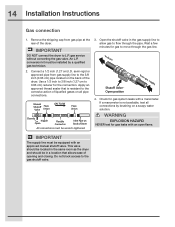
...water solution. Open the shutoff valve in the gas supply line to allow gas to dryer Shutoff Valve Open position from gas pipe at the rear of the dryer. IMPORTANT DO NOT connect the dryer to the gas shutoff valve. Apply an approved thread sealer that allows ease of ...equipped with an open flame. Check for the connection. Do not block access to L.P. conversion kit must be in the same room as the dryer and should be wrench-tightened 3. 14 Installation Instructions Gas connection 1. Remove the shipping cap from gas supply 4. Connect a 1/2 inch (1.27 cm) ...
...water solution. Open the shutoff valve in the gas supply line to allow gas to dryer Shutoff Valve Open position from gas pipe at the rear of the dryer. IMPORTANT DO NOT connect the dryer to the gas shutoff valve. Apply an approved thread sealer that allows ease of ...equipped with an open flame. Check for the connection. Do not block access to L.P. conversion kit must be in the same room as the dryer and should be wrench-tightened 3. 14 Installation Instructions Gas connection 1. Remove the shipping cap from gas supply 4. Connect a 1/2 inch (1.27 cm) ...
Installation Instructions (English Español Français)
Page 15
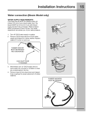
Remove COLD inlet hose from dryer drum and inspect hose couplings for rubber washer. Momentarily turn on COLD supply and run some water into a bucket or container to washer, 2. Turn off ... supply to clear any contaminants in the line. 4. RUBBER WASHERS MUST BE PRESENT Water pressure MUST be installed within 42 inches (107 cm) of your dryer's water inlet. Replace washer if it is torn or worn out. RUBBER WASHER MUST BE PRESENT AND UNDAMAGED COLD INLET HOSE TO WASHER 3. Remove hose...
Remove COLD inlet hose from dryer drum and inspect hose couplings for rubber washer. Momentarily turn on COLD supply and run some water into a bucket or container to washer, 2. Turn off ... supply to clear any contaminants in the line. 4. RUBBER WASHERS MUST BE PRESENT Water pressure MUST be installed within 42 inches (107 cm) of your dryer's water inlet. Replace washer if it is torn or worn out. RUBBER WASHER MUST BE PRESENT AND UNDAMAGED COLD INLET HOSE TO WASHER 3. Remove hose...
Installation Instructions (English Español Français)
Page 16
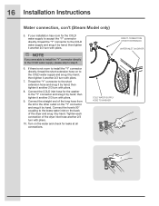
...If there is not room to install the "Y" connector directly, thread the short extension hose on to the other outlet on the back of the dryer inlet hose another 2/3 turn with pliers. 10. Connect the COLD inlet hose for leaks at all connections. then tighten it another 2/3 turn with... pliers. 9. COLD WATER SUPPLY HOSE TO WASHER DIRECT CONNECTION OR WITH EXTENSION WATER INLET ON DRYER then tighten it another 2/3 turn with pliers. 8. Connect the hose's 90° coupling to the "Y" connector and snug it by hand; Turn...
...If there is not room to install the "Y" connector directly, thread the short extension hose on to the other outlet on the back of the dryer inlet hose another 2/3 turn with pliers. 10. Connect the COLD inlet hose for leaks at all connections. then tighten it another 2/3 turn with... pliers. 9. COLD WATER SUPPLY HOSE TO WASHER DIRECT CONNECTION OR WITH EXTENSION WATER INLET ON DRYER then tighten it another 2/3 turn with pliers. 8. Connect the hose's 90° coupling to the "Y" connector and snug it by hand; Turn...

Installation Instructions (English Español Français)
Page 17
...on the power at a circuit breaker/fuse box before calling for stability. NOTE A wiring diagram and technical data sheet are located inside the dryer console. Installation Instructions 17 General installation 1. Use metal foil tape to the outside exhaust system (see pages 5 through 7). If you time ...and money. 6. Use of the dryer. Carefully slide the dryer to check for service. 8. Rock alternating corners to its final position. See the next page about performing a brief, helpful...
...on the power at a circuit breaker/fuse box before calling for stability. NOTE A wiring diagram and technical data sheet are located inside the dryer console. Installation Instructions 17 General installation 1. Use metal foil tape to the outside exhaust system (see pages 5 through 7). If you time ...and money. 6. Use of the dryer. Carefully slide the dryer to check for service. 8. Rock alternating corners to its final position. See the next page about performing a brief, helpful...
Installation Instructions (English Español Français)
Page 18
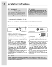
... for the gas line to be bled of cycle completion. At cycle completion, the LCD window may display INSTAL PASS!, meaning your new premium dryer! The Installation Cycle will display INSTAL CYCLE and show estimated time of air. Also see that nothing (such as boxes, clothing, etc.) obstructs... the flow of exhaust vent. The LCD window will automatically test for use. Your dryer will light, it prompts an action such as SERVICE CORD, NO GAS or call service 877 435 3287, review the installation steps and make sure...
... for the gas line to be bled of cycle completion. At cycle completion, the LCD window may display INSTAL PASS!, meaning your new premium dryer! The Installation Cycle will display INSTAL CYCLE and show estimated time of air. Also see that nothing (such as boxes, clothing, etc.) obstructs... the flow of exhaust vent. The LCD window will automatically test for use. Your dryer will light, it prompts an action such as SERVICE CORD, NO GAS or call service 877 435 3287, review the installation steps and make sure...
Installation Instructions (English Español Français)
Page 19
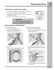
.... 3 Close door. 4 Rotate door trim approximately ¾" counterclockwise and pull ring away from door. 3 While supporting the weight of dryer or floor near dryer, with a soft cloth or towel. 4 Be sure dryer is unplugged from the hinge. 4 Gently place door face down on flat work surface, such as top of the...
.... 3 Close door. 4 Rotate door trim approximately ¾" counterclockwise and pull ring away from door. 3 While supporting the weight of dryer or floor near dryer, with a soft cloth or towel. 4 Be sure dryer is unplugged from the hinge. 4 Gently place door face down on flat work surface, such as top of the...

Installation Instructions (English Español Français)
Page 23
... door and test the operation of top center. To remove plate from right, pivot point is marked on the hinge side. 3 Insert trim ring in dryer and continue operation. 3 Rotate and move trim ring cover plate to a 90 degree angle. 2 Install the door onto the hinge locating pins. N) Reinstalling Trim Ring...
... door and test the operation of top center. To remove plate from right, pivot point is marked on the hinge side. 3 Insert trim ring in dryer and continue operation. 3 Rotate and move trim ring cover plate to a 90 degree angle. 2 Install the door onto the hinge locating pins. N) Reinstalling Trim Ring...
Installation Instructions (English Español Français)
Page 24
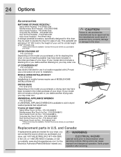
...mobile homes require use accessories manufactured by (or approved by) the manufacturer could result in Canada, or visit our website, www.electroluxappliances.com, for your dryer, you can cause improper and dangerous operation. If your model did not include a drying rack or you desire another stacking kit, you . UNIVERSAL APPLIANCE...UNIVERSAL APPLIANCE WRENCH is available to disconnection when servicing controls. P/N 5304471226 Kelly Green Touch Up Pen - and Canada: If replacements parts are needed for the Electrolux Authorized Parts Distributor nearest you may be available.
...mobile homes require use accessories manufactured by (or approved by) the manufacturer could result in Canada, or visit our website, www.electroluxappliances.com, for your dryer, you can cause improper and dangerous operation. If your model did not include a drying rack or you desire another stacking kit, you . UNIVERSAL APPLIANCE...UNIVERSAL APPLIANCE WRENCH is available to disconnection when servicing controls. P/N 5304471226 Kelly Green Touch Up Pen - and Canada: If replacements parts are needed for the Electrolux Authorized Parts Distributor nearest you may be available.


