
PDF Spec Sheet
Page 1
... possible variable power switching The EVGA Z68 motherboards have a backup, compare BIOS versions or use 3 separate profiles! Intel® Smart Response Technology implements a storage I/O caching system to 16GB) • 2 1394 Ports (firewire, one rear panel, one onboard) • 6 PCI Express 2.0 Graphics Expansion Slots • 2 Gigabit Ethernet Ports (10/100/1000) • 10 USB 2.0 Ports (six rear panel, four onboard) • 8 Channel High Definition Audio • EATX Form Factor EVGA E-LEET Tuning Utility Enthusiast software for adjusting overclocking in CPU pins, lower...
... possible variable power switching The EVGA Z68 motherboards have a backup, compare BIOS versions or use 3 separate profiles! Intel® Smart Response Technology implements a storage I/O caching system to 16GB) • 2 1394 Ports (firewire, one rear panel, one onboard) • 6 PCI Express 2.0 Graphics Expansion Slots • 2 Gigabit Ethernet Ports (10/100/1000) • 10 USB 2.0 Ports (six rear panel, four onboard) • 8 Channel High Definition Audio • EATX Form Factor EVGA E-LEET Tuning Utility Enthusiast software for adjusting overclocking in CPU pins, lower...
PDF Spec Sheet
Page 2
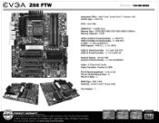
...6.0Gb/s Ports/Controller - 2 / Z68 PCH E-SATA - 2 / Marvell 88SE6121 RAID Support - For more details please visit www.evga.com/warranty/ 623 CHIPSET Z68 inside ' 741 111/IDIA IBBI=0301111 1C1107 CORE'" 17 CORE- PCIE XI 41. I . ft PCIE X0_3 :on iffs 3- : . Intel° Core'"" i5 and Corer" i7 Socket 1155 Socket Type - RAID 0, 1, 5, 10, JBOD USB 2.0 Ports/Controller - 10 / Intel° Z68 PCH USB 3.0 Ports/Controller - 4 / VLI VL800-Q8 Network Speed - 10/100/1000 Network Ports/Controller - 2 / Marvell 88E8057 Audio - 8 Channel HD Audio Audio Controller - AMI / UEFI Software...
...6.0Gb/s Ports/Controller - 2 / Z68 PCH E-SATA - 2 / Marvell 88SE6121 RAID Support - For more details please visit www.evga.com/warranty/ 623 CHIPSET Z68 inside ' 741 111/IDIA IBBI=0301111 1C1107 CORE'" 17 CORE- PCIE XI 41. I . ft PCIE X0_3 :on iffs 3- : . Intel° Core'"" i5 and Corer" i7 Socket 1155 Socket Type - RAID 0, 1, 5, 10, JBOD USB 2.0 Ports/Controller - 10 / Intel° Z68 PCH USB 3.0 Ports/Controller - 4 / VLI VL800-Q8 Network Speed - 10/100/1000 Network Ports/Controller - 2 / Marvell 88E8057 Audio - 8 Channel HD Audio Audio Controller - AMI / UEFI Software...
User Guide
Page 5
This board is based off of the new Intel Z68/P67 chipset with the added bonus of EVGA's industry leading 24/7 technical support in case you need it. As always this board comes with native support for SATA III/6G for purchasing the EVGA Z68/P67 Motherboard. EVGA Z68/P67 Motherboard Thank you for the performance you demand, delivered when you ever have any issues or questions.
This board is based off of the new Intel Z68/P67 chipset with the added bonus of EVGA's industry leading 24/7 technical support in case you need it. As always this board comes with native support for SATA III/6G for purchasing the EVGA Z68/P67 Motherboard. EVGA Z68/P67 Motherboard Thank you for the performance you demand, delivered when you ever have any issues or questions.

User Guide
Page 6
... processor PCI Express Graphics Card Power Supply EVGA assumes you will need many of the cables. If however, you are building a PC, you with the motherboard and all the hardware necessary to make the motherboard functional. Intel Socket 1155 Processor DDR3 System Memory Socket 775 or 1155/1156 CPU cooler for proper system functionality. EVGA Z68/P67 Motherboard This kit contains all connecting cables necessary to install...
... processor PCI Express Graphics Card Power Supply EVGA assumes you will need many of the cables. If however, you are building a PC, you with the motherboard and all the hardware necessary to make the motherboard functional. Intel Socket 1155 Processor DDR3 System Memory Socket 775 or 1155/1156 CPU cooler for proper system functionality. EVGA Z68/P67 Motherboard This kit contains all connecting cables necessary to install...
User Guide
Page 7
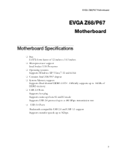
EVGA Z68/P67 Motherboard Size EATX form factor of DDR3 memory. USB 2.0 Ports Supports hot plug Supports wake-up from S1 and S3 mode Supports USB 2.0 protocol up to a 480 Mbps transmission rate USB 3.0 Ports Backwards compatible USB 2.0 and USB 1.1 support Supports transfer speeds up to 5Gbps Officially supports up to 16GBs of 12 inches x 10.3 inches Microprocessor support Intel Socket 1155 Processor Operating systems: Supports Windows XP/Vista/7 32 and 64 bit Contains...
EVGA Z68/P67 Motherboard Size EATX form factor of DDR3 memory. USB 2.0 Ports Supports hot plug Supports wake-up from S1 and S3 mode Supports USB 2.0 protocol up to a 480 Mbps transmission rate USB 3.0 Ports Backwards compatible USB 2.0 and USB 1.1 support Supports transfer speeds up to 5Gbps Officially supports up to 16GBs of 12 inches x 10.3 inches Microprocessor support Intel Socket 1155 Processor Operating systems: Supports Windows XP/Vista/7 32 and 64 bit Contains...

User Guide
Page 8
EVGA Z68/P67 Motherboard SATA ports up to 3.0 Gb/s (300 M/s) data transfer rate SATA ports up to 6.0 Gb/s (600 M/s) data transfer rate Support for RAID 0, RAID 1, RAID 0+1, RAID5 and RAID 10 ESATA (optional) Onboard LAN Supports 10/100/1000 Mbit/sec Ethernet Onboard IEEE 1394a (Firewire) Supports hot plug Onboard Audio Realtek High-Definition audio Supports 8-channel audio Supports Jack-Sensing function PCI-E Support PCI-E 2.0 Slots Low power consumption and power management features Green Function Supports ACPI (Advanced Configuration ...
EVGA Z68/P67 Motherboard SATA ports up to 3.0 Gb/s (300 M/s) data transfer rate SATA ports up to 6.0 Gb/s (600 M/s) data transfer rate Support for RAID 0, RAID 1, RAID 0+1, RAID5 and RAID 10 ESATA (optional) Onboard LAN Supports 10/100/1000 Mbit/sec Ethernet Onboard IEEE 1394a (Firewire) Supports hot plug Onboard Audio Realtek High-Definition audio Supports 8-channel audio Supports Jack-Sensing function PCI-E Support PCI-E 2.0 Slots Low power consumption and power management features Green Function Supports ACPI (Advanced Configuration ...
User Guide
Page 10
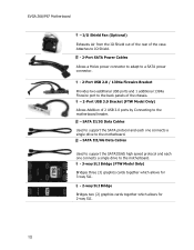
EVGA Z68/P67 Motherboard - I/O Shield Fan (Optional) Exhausts Air from the IO Shield out of the rear of 2 USB 3.0 ports by Connecting to the back panels of the chassis. - 2-Port USB 3.0 Bracket (FTW Model Only) Allows Addition of the case. Attaches to IO Shield. - 2-Port SATA Power Cables Allows a Molex power connector to adapt to a SATA power connector. - 2-Port USB 2.0 / 1394a Firewire Bracket Provides two additional USB ports and 1 additional 1394a Firewire port to the motherboard header. - SATA III/6G Data Cables Used to support the...
EVGA Z68/P67 Motherboard - I/O Shield Fan (Optional) Exhausts Air from the IO Shield out of the rear of 2 USB 3.0 ports by Connecting to the back panels of the chassis. - 2-Port USB 3.0 Bracket (FTW Model Only) Allows Addition of the case. Attaches to IO Shield. - 2-Port SATA Power Cables Allows a Molex power connector to adapt to a SATA power connector. - 2-Port USB 2.0 / 1394a Firewire Bracket Provides two additional USB ports and 1 additional 1394a Firewire port to the motherboard header. - SATA III/6G Data Cables Used to support the...
User Guide
Page 11
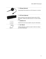
ECP Panel (Optional) Allows monitoring of post codes and remote control of PCIe slot disable, voltages and CMOS reset all on one bay mounted panel. - EVGauge (Optional) Analog Gauge that represents your EVGA Motherboard. Installation CD Contains drivers and soare needed to setup the motherboard. - User Manual Contains Information needed to properly install and configure your CPU frequency in real time. - EVGA Z68/P67 Motherboard -
ECP Panel (Optional) Allows monitoring of post codes and remote control of PCIe slot disable, voltages and CMOS reset all on one bay mounted panel. - EVGauge (Optional) Analog Gauge that represents your EVGA Motherboard. Installation CD Contains drivers and soare needed to setup the motherboard. - User Manual Contains Information needed to properly install and configure your CPU frequency in real time. - EVGA Z68/P67 Motherboard -
User Guide
Page 14
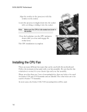
... for Socket 775 heatsinks. Close the load plate over the CPU and press down into the socket with notches on the socket. Align notches with out tilting or sliding it into the socket. Be sure that came with this motherboard. The other holes are labeled. Follow the instruction that the fan orientation is complete. Please note that can be used. EVGA Z68/P67 Motherboard...
... for Socket 775 heatsinks. Close the load plate over the CPU and press down into the socket with notches on the socket. Align notches with out tilting or sliding it into the socket. Be sure that came with this motherboard. The other holes are labeled. Follow the instruction that the fan orientation is complete. Please note that can be used. EVGA Z68/P67 Motherboard...

User Guide
Page 16
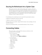
... make all the connections. EVGA Z68/P67 Motherboard The sequence of installing the motherboard into a system case depends on the chassis you are replacing an existing motherboard or working with the vents on the system case being used to block radio frequency transmissions, protects internal components from the chassis supplier. Also Note that is aligned with an empty system case. Note: Be sure that the CPU fan assembly has...
... make all the connections. EVGA Z68/P67 Motherboard The sequence of installing the motherboard into a system case depends on the chassis you are replacing an existing motherboard or working with the vents on the system case being used to block radio frequency transmissions, protects internal components from the chassis supplier. Also Note that is aligned with an empty system case. Note: Be sure that the CPU fan assembly has...
User Guide
Page 17
... the motherboard to be secured to the chassis and help to prevent short circuits. This will include: Power Connections 24-pin ATX power (PW1) 8-pin ATX 12V power (PW12-1 & PW12-2) Internal Headers Front Panel Header IEEE 1394a Header USB Headers Audio Header SATA II SATA III Chassis Fans USB 2.0 EVGA Z68/P67 Motherboard Most system cases have a base with the stand offs. 3. Ensure that stud to the fan assembly instruction. 5. Secure the motherboard with the chassis vents...
... the motherboard to be secured to the chassis and help to prevent short circuits. This will include: Power Connections 24-pin ATX power (PW1) 8-pin ATX 12V power (PW12-1 & PW12-2) Internal Headers Front Panel Header IEEE 1394a Header USB Headers Audio Header SATA II SATA III Chassis Fans USB 2.0 EVGA Z68/P67 Motherboard Most system cases have a base with the stand offs. 3. Ensure that stud to the fan assembly instruction. 5. Secure the motherboard with the chassis vents...

User Guide
Page 19
... used to provide power to the right of the PC speaker on . The addition of 3 physical BIOS chips on the mainboard allows for usage of three completely different bios versions or saving of profiles to the connector and press firmly until seated. Align the pins to differentiate between bench sessions and regular 24/7 usage. EVGA Z68/P67 Motherboard PW12-1 & PW12-2, the 8-pin ATX 12V power connection, is powered...
... used to provide power to the right of the PC speaker on . The addition of 3 physical BIOS chips on the mainboard allows for usage of three completely different bios versions or saving of profiles to the connector and press firmly until seated. Align the pins to differentiate between bench sessions and regular 24/7 usage. EVGA Z68/P67 Motherboard PW12-1 & PW12-2, the 8-pin ATX 12V power connection, is powered...
User Guide
Page 20
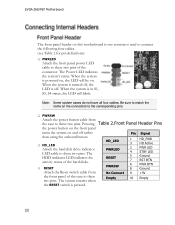
... Attach the Reset switch cable from the case to these two pins. When the system is off rather than using the onboard button. HD_LED Attach the hard disk drive indicator LED cable to these two pins. Note: Some system cases do not have all four cables. Be sure to match the name on and off . EVGA Z68/P67 Motherboard The front panel header on this motherboard is one connector used to connect the following...
... Attach the Reset switch cable from the case to these two pins. When the system is off rather than using the onboard button. HD_LED Attach the hard disk drive indicator LED cable to these two pins. Note: Some system cases do not have all four cables. Be sure to match the name on and off . EVGA Z68/P67 Motherboard The front panel header on this motherboard is one connector used to connect the following...

User Guide
Page 26
... constant power. Debug LED with CPU Temperature Monitor Theses LEDs indicate the system's status. POWER LED (Green): When the System is powered on: This LED is on. DIMM LED (Yellow): When the Memory slot is functional: This LED is on. STANDBY LED (Blue): When the System is in Standby Mode: This LED is on as long as the motherboard is useful during troubleshooting situations. EVGA Z68/P67 Motherboard Provides two-digit POST codes...
... constant power. Debug LED with CPU Temperature Monitor Theses LEDs indicate the system's status. POWER LED (Green): When the System is powered on: This LED is on. DIMM LED (Yellow): When the Memory slot is functional: This LED is on. STANDBY LED (Blue): When the System is in Standby Mode: This LED is on as long as the motherboard is useful during troubleshooting situations. EVGA Z68/P67 Motherboard Provides two-digit POST codes...

User Guide
Page 27
... that before installing the driver CD that contains utilities, drivers, and additional soare. The kit comes with the EVGA Z68/P67 Motherboard contains the following software and drivers: Chipset Drivers Audio Drivers RAID Drivers LAN Drivers Matrix Storage USB 3.0 Drivers EVGA E-LEET User's Manual 1. The CD will autorun, install the drivers and utilities listed on the CD to open. The motherboard supports Windows XP , Vista and Windows 7 both 32 and 64 Bit. EVGA Z68/P67 Motherboard Note...
... that before installing the driver CD that contains utilities, drivers, and additional soare. The kit comes with the EVGA Z68/P67 Motherboard contains the following software and drivers: Chipset Drivers Audio Drivers RAID Drivers LAN Drivers Matrix Storage USB 3.0 Drivers EVGA E-LEET User's Manual 1. The CD will autorun, install the drivers and utilities listed on the CD to open. The motherboard supports Windows XP , Vista and Windows 7 both 32 and 64 Bit. EVGA Z68/P67 Motherboard Note...
User Guide
Page 28
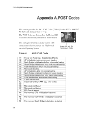
... is started The POST Codes are displayed on . Pre-memory CPU initialization is started 14 15- AMI POST Code 01 Power on the Debug LED readout located directly onboard the motherboard. This Debug LED will also display current CPU temperatures after microcode loading 0B Cache initialization 0C- Debug LED with CPU Temperature Monitor Table 6. Reserved for the EVGA Z68/P67 Motherboard during system boot up. EVGA Z68/P67 Motherboard This section provides the AMI POST Codes (Table 6) for future AMI SEC error codes 0D...
... is started The POST Codes are displayed on . Pre-memory CPU initialization is started 14 15- AMI POST Code 01 Power on the Debug LED readout located directly onboard the motherboard. This Debug LED will also display current CPU temperatures after microcode loading 0B Cache initialization 0C- Debug LED with CPU Temperature Monitor Table 6. Reserved for the EVGA Z68/P67 Motherboard during system boot up. EVGA Z68/P67 Motherboard This section provides the AMI POST Codes (Table 6) for future AMI SEC error codes 0D...
User Guide
Page 29
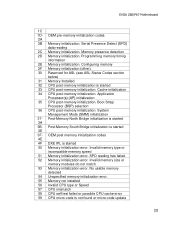
... Memory initialization. EVGA Z68/P67 Motherboard 1C 1D- Invalid memory size or memory modules do not match. 53 Memory initialization error. Programming memory timing information 2E Memory initialization. Application Processor(s) (AP) initialization 35 CPU post-memory initialization. Invalid memory type or incompatible memory speed 51 Memory initialization error. No usable memory detected 54 Unspecified memory initialization error. 55 Memory not installed 56 Invalid CPU type or Speed 57 CPU mismatch 58 CPU self test failed or possible CPU cache error 59 CPU micro-code is started...
... Memory initialization. EVGA Z68/P67 Motherboard 1C 1D- Invalid memory size or memory modules do not match. 53 Memory initialization error. Programming memory timing information 2E Memory initialization. Application Processor(s) (AP) initialization 35 CPU post-memory initialization. Invalid memory type or incompatible memory speed 51 Memory initialization error. No usable memory detected 54 Unspecified memory initialization error. 55 Memory not installed 56 Invalid CPU type or Speed 57 CPU mismatch 58 CPU self test failed or possible CPU cache error 59 CPU micro-code is started...
User Guide
Page 31
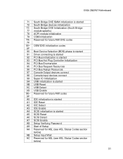
... module specific) 78 ACPI module initialization 79 CSM initialization 7A- Reserved for future AMI codes 9F A0 IDE initialization is started A1 IDE Reset A2 IDE Detect A3 IDE Enable A4 SCSI initialization is started 9B USB Reset 9C USB Detect 9D USB Enable 9E- OEM DXE initialization codes 8F 90 Boot Device Selection (BDS) phase is started 91 Driver connecting is started 92 PCI Bus initialization is started 93 PCI Bus Hot Plug Controller Initialization 94 PCI Bus Enumeration 95 PCI Bus Request...
... module specific) 78 ACPI module initialization 79 CSM initialization 7A- Reserved for future AMI codes 9F A0 IDE initialization is started A1 IDE Reset A2 IDE Detect A3 IDE Enable A4 SCSI initialization is started 9B USB Reset 9C USB Detect 9D USB Enable 9E- OEM DXE initialization codes 8F 90 Boot Device Selection (BDS) phase is started 91 Driver connecting is started 92 PCI Bus initialization is started 93 PCI Bus Hot Plug Controller Initialization 94 PCI Bus Enumeration 95 PCI Bus Request...

User Guide
Page 32
... Resources D5 No Space for future AMI codes BF C0- EVGA Z68/P67 Motherboard AD Ready To Boot event AE Legacy Boot event AF Exit Boot Services event B0 Runtime Set Virtual Address MAP Begin B1 Runtime Set Virtual Address MAP End B2 Legacy Option ROM Initialization B3 System Reset B4 USB hot plug B5 PCI bus hot plug B6 Clean-up of NVRAM B7 Configuration Reset (reset of the Architectural Protocols are found D7...
... Resources D5 No Space for future AMI codes BF C0- EVGA Z68/P67 Motherboard AD Ready To Boot event AE Legacy Boot event AF Exit Boot Services event B0 Runtime Set Virtual Address MAP Begin B1 Runtime Set Virtual Address MAP End B2 Legacy Option ROM Initialization B3 System Reset B4 USB hot plug B5 PCI bus hot plug B6 Clean-up of NVRAM B7 Configuration Reset (reset of the Architectural Protocols are found D7...

User Guide
Page 35
... Digital Interconnect Format SPP - Universal Serial Bus VDroop - Red Green Blue SATA - Split Frame Rendering SLI - Serial Presence Detect SPDIF - Peripheral Component Interconnect PCIe - OEM - Serial Advanced Technology Attachment SB - Solid State Drive TCP/IP - Power on Self Test PWM - Video Graphics Array EVGA Z68/P67 Motherboard Peripheral Component Interconnect Extended POST - Quick Path Interconnect RAID - Southbridge SCSI - Transmission Control Protocol/Internet Protocol USB - Parallel Advanced Technology Attachment PCB - Printed Circuit...
... Digital Interconnect Format SPP - Universal Serial Bus VDroop - Red Green Blue SATA - Split Frame Rendering SLI - Serial Presence Detect SPDIF - Peripheral Component Interconnect PCIe - OEM - Serial Advanced Technology Attachment SB - Solid State Drive TCP/IP - Power on Self Test PWM - Video Graphics Array EVGA Z68/P67 Motherboard Peripheral Component Interconnect Extended POST - Quick Path Interconnect RAID - Southbridge SCSI - Transmission Control Protocol/Internet Protocol USB - Parallel Advanced Technology Attachment PCB - Printed Circuit...


