
User Guide
Page 2
... of Contents Before You Begin 4 Motherboard Specifications 5 Unpacking and Parts Descriptions 6-7 Equipment ...8-9 Hardware Installation 10 Installing the CPU 11-12 Installing the Cooling Device 13 Installing DIMMs 13 Installing the Motherboard 14 Motherboard I/O Panel 14 Securing the Motherboard into the Chassis 15 Connecting Cables and Setting Switches 16 24-pin ATX Power (PW1 16 8-pin ATX 12V Power (PW12-P0-1, PW12-P1-1 17 Connecting Serial ATA Cables 18 Front Panel Header 19 USB Headers ...20 Audio Header...21 Fan Connections 22 Expansion Slots 23 PCI-E x16 Slots 24 2
... of Contents Before You Begin 4 Motherboard Specifications 5 Unpacking and Parts Descriptions 6-7 Equipment ...8-9 Hardware Installation 10 Installing the CPU 11-12 Installing the Cooling Device 13 Installing DIMMs 13 Installing the Motherboard 14 Motherboard I/O Panel 14 Securing the Motherboard into the Chassis 15 Connecting Cables and Setting Switches 16 24-pin ATX Power (PW1 16 8-pin ATX 12V Power (PW12-P0-1, PW12-P1-1 17 Connecting Serial ATA Cables 18 Front Panel Header 19 USB Headers ...20 Audio Header...21 Fan Connections 22 Expansion Slots 23 PCI-E x16 Slots 24 2

User Guide
Page 3
EVGA Classified SR-X Motherboard Onboard Buttons 25 Post Port Debug LED and LED Status Indicators 26 PCIE-E Disable Swtiches 27 CPU1 Disable Swtiches 28 DIMM Disable Swtiches 29 Voltage Measure Point 30 Installing Drivers and Software 31 POST Codes 32-33 EVGA Glossary of Terms 34-36 Compliance Information 37 3
EVGA Classified SR-X Motherboard Onboard Buttons 25 Post Port Debug LED and LED Status Indicators 26 PCIE-E Disable Swtiches 27 CPU1 Disable Swtiches 28 DIMM Disable Swtiches 29 Voltage Measure Point 30 Installing Drivers and Software 31 POST Codes 32-33 EVGA Glossary of Terms 34-36 Compliance Information 37 3

User Guide
Page 5
...-Channel DDR3 1600MHz+ (Up to install the motherboard into a PC case. If you are replacing a motherboard, you with the motherboard and all connecting cables necessary to 96GB) PCI Express 3.0 Ready 7 PCI Express Graphics Expansion Slots 10 USB 2.0 Ports (four rear panel, six onboard) 6 USB 3.0 Ports (four rear panel, two onboard) Supports Bluetooth 2 SATA III/6G Ports (2-ESATA) 4 SATA II/3G Ports 2 Mini SAS Ports 1 1394b Header (Firewire, One Onboard) 2 Gigabit Ethernet Ports...
...-Channel DDR3 1600MHz+ (Up to install the motherboard into a PC case. If you are replacing a motherboard, you with the motherboard and all connecting cables necessary to 96GB) PCI Express 3.0 Ready 7 PCI Express Graphics Expansion Slots 10 USB 2.0 Ports (four rear panel, six onboard) 6 USB 3.0 Ports (four rear panel, two onboard) Supports Bluetooth 2 SATA III/6G Ports (2-ESATA) 4 SATA II/3G Ports 2 Mini SAS Ports 1 1394b Header (Firewire, One Onboard) 2 Gigabit Ethernet Ports...
User Guide
Page 7
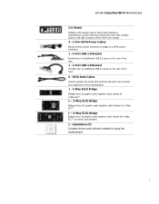
... (2) additional USB 3.0 ports on select card models) 1 - EVGA Classified SR-X Motherboard I/O Shield Installs in the system case to block radio frequency transmissions, protect internal components from dust, foreign objects, and aids in proper airflow within the chassis. 3 - 2-Port SATA Power Cables Allows a Molex power connector to adapt to a SATA power connector. 1 - 4-Port USB 2.0 Bracket Provides four (4) additional USB 2.0 ports on the rear of the case. 6 - SATA Data Cables Used to support the Serial ATA protocol and each one connects to setup the motherboard. 7
... (2) additional USB 3.0 ports on select card models) 1 - EVGA Classified SR-X Motherboard I/O Shield Installs in the system case to block radio frequency transmissions, protect internal components from dust, foreign objects, and aids in proper airflow within the chassis. 3 - 2-Port SATA Power Cables Allows a Molex power connector to adapt to a SATA power connector. 1 - 4-Port USB 2.0 Bracket Provides four (4) additional USB 2.0 ports on the rear of the case. 6 - SATA Data Cables Used to support the Serial ATA protocol and each one connects to setup the motherboard. 7

User Guide
Page 8
...(SATA) connectors 11. CMOS clear button 18. Front panel connector 13. USB headers 15. 6 Pin power for PCI-E slots 16. PC Speaker 21. CPU Fan headers 5. Fan headers 8. EZ voltage read points 17. Power button 7 6 10 13 8 9 11 12 7 19 18 17 19. Front panel Audio connector 25. CPU1 disable switch 8 Primary CPU socket 2. Mini-SAS connectors 4 22 23 7 3 20 5 14 10. Reset button 20. EVGA Classified SR-X Motherboard Figure 1. Intel® C606 Chipset 6. 24-pin ATX power connector 7. USB 3.0 header 12. Debug LED Display 14. PCI-E 3.0 slots 22. 8-pin ATX_12V...
...(SATA) connectors 11. CMOS clear button 18. Front panel connector 13. USB headers 15. 6 Pin power for PCI-E slots 16. PC Speaker 21. CPU Fan headers 5. Fan headers 8. EZ voltage read points 17. Power button 7 6 10 13 8 9 11 12 7 19 18 17 19. Front panel Audio connector 25. CPU1 disable switch 8 Primary CPU socket 2. Mini-SAS connectors 4 22 23 7 3 20 5 14 10. Reset button 20. EVGA Classified SR-X Motherboard Figure 1. Intel® C606 Chipset 6. 24-pin ATX power connector 7. USB 3.0 header 12. Debug LED Display 14. PCI-E 3.0 slots 22. 8-pin ATX_12V...
User Guide
Page 13
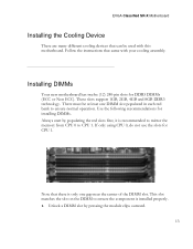
... technology. Use the following recommendations for CPU 1. EVGA Classified SR-X Motherboard Installing the Cooling Device There are many different cooling devices that can be at least one gap near the center of the DIMM slot. Note that came with this motherboard. Installing DIMMs Your new motherboard has twelve (12) 240-pin slots for DDR3 DIMMs (ECC or Non ECC). Follow the instructions that there is installed...
... technology. Use the following recommendations for CPU 1. EVGA Classified SR-X Motherboard Installing the Cooling Device There are many different cooling devices that can be at least one gap near the center of the DIMM slot. Note that came with this motherboard. Installing DIMMs Your new motherboard has twelve (12) 240-pin slots for DDR3 DIMMs (ECC or Non ECC). Follow the instructions that there is installed...

User Guide
Page 14
... install the I /O shield that the CPU fan assembly has enough clearance for the expansion cards. Also make sure the CPU Fan assembly is aligned with the vents on the chassis you are replacing an existing motherboard or working with an I /O shield and secure the motherboard into place and for the chassis covers to secure the motherboard first. It is used to make all the connections...
... install the I /O shield that the CPU fan assembly has enough clearance for the expansion cards. Also make sure the CPU Fan assembly is aligned with the vents on the chassis you are replacing an existing motherboard or working with an I /O shield and secure the motherboard into place and for the chassis covers to secure the motherboard first. It is used to make all the connections...
User Guide
Page 16
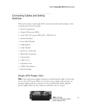
...Headers Audio Header SATA II / SATA III Mini-SAS Connectors Chassis Fans USB 2.0/3.0 Expansion slots CMOS Clear Button Switch Settings 24-pin ATX Power (PW1) PW1 is secure. EVGA Classified SR-X Motherboard Connecting Cables and Setting Switches This section takes you through all the connections and switch settings on the motherboard. Make sure that the power supply cable and pins are properly aligned with the connector on the motherboard. PW1 connector 16 Plug power cable from system power supply to the SATA ports...
...Headers Audio Header SATA II / SATA III Mini-SAS Connectors Chassis Fans USB 2.0/3.0 Expansion slots CMOS Clear Button Switch Settings 24-pin ATX Power (PW1) PW1 is secure. EVGA Classified SR-X Motherboard Connecting Cables and Setting Switches This section takes you through all the connections and switch settings on the motherboard. Make sure that the power supply cable and pins are properly aligned with the connector on the motherboard. PW1 connector 16 Plug power cable from system power supply to the SATA ports...

User Guide
Page 17
It is an ATX 12V differential output, and not a PCI-E power connector. 17 Before installing these plugs be ensure that the 8-pin connector is not necessary or required as the motherboard will function perfectly with just one connector in the extra 6 pin PCI-E power connectors (optional) if you need them for extreme overclocking. EVGA Classified SR-X Motherboard Table 1. You can plug in each 8 pin socket. PW1 Pin Assignments Connector Pin Signal Board edg1e +3.3V 24 13...
It is an ATX 12V differential output, and not a PCI-E power connector. 17 Before installing these plugs be ensure that the 8-pin connector is not necessary or required as the motherboard will function perfectly with just one connector in the extra 6 pin PCI-E power connectors (optional) if you need them for extreme overclocking. EVGA Classified SR-X Motherboard Table 1. You can plug in each 8 pin socket. PW1 Pin Assignments Connector Pin Signal Board edg1e +3.3V 24 13...
User Guide
Page 18
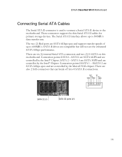
... (6) internal Serial ATA connectors and two (2) E-SATA on this motherboard. SATA1 are SATA 6GPS and are compatible but will not see the enhanced SATA 6Gbps performance. RX+ TX- These connectors support the thin Serial ATA II cables for primary storage devices. Connection points SATA0 - SATA II drives are controlled by the Intel® Chipset. RX- TX+ GND GND GND SATA II 2-5 SATA III ports 0/1 18 EVGA Classified SR-X Motherboard Connecting Serial ATA Cables The Serial ATA II connector is used...
... (6) internal Serial ATA connectors and two (2) E-SATA on this motherboard. SATA1 are SATA 6GPS and are compatible but will not see the enhanced SATA 6Gbps performance. RX+ TX- These connectors support the thin Serial ATA II cables for primary storage devices. Connection points SATA0 - SATA II drives are controlled by the Intel® Chipset. RX- TX+ GND GND GND SATA II 2-5 SATA III ports 0/1 18 EVGA Classified SR-X Motherboard Connecting Serial ATA Cables The Serial ATA II connector is used...
User Guide
Page 19
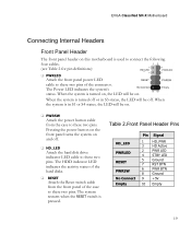
... Pressing the power button on the front panel turns the system on and off . When the system is turned on, the LED will be on. EVGA Classified SR-X Motherboard Connecting Internal Headers Front Panel Header The front panel header on this motherboard is used to connect the following four cables. (see Table 2 for pin definitions): PWRLED Attach the front panel power LED cable to these two pins. The system restarts when the RESET switch is pressed...
... Pressing the power button on the front panel turns the system on and off . When the system is turned on, the LED will be on. EVGA Classified SR-X Motherboard Connecting Internal Headers Front Panel Header The front panel header on this motherboard is used to connect the following four cables. (see Table 2 for pin definitions): PWRLED Attach the front panel power LED cable to these two pins. The system restarts when the RESET switch is pressed...

User Guide
Page 20
... rear panel of the USB cable to the USB 2.0/3.0 headers on the motherboard. It also contains one 19-pin onboard header that can be used to connect an optional external bracket containing (2) USB 3.0 ports that are exposed on the back panel which can be used to connect an optional external bracket containing six (6) USB 2.0 ports. Connect the end of your chassis. 2. EVGA Classified SR-X Motherboard USB Headers This motherboard contains four (4) USB 2.0 ports that are backwards compatible with USB 2.0. 1. USB 2.0 Header Pins Connector USB 2.0 Header Connector Pin Signal...
... rear panel of the USB cable to the USB 2.0/3.0 headers on the motherboard. It also contains one 19-pin onboard header that can be used to connect an optional external bracket containing (2) USB 3.0 ports that are exposed on the back panel which can be used to connect an optional external bracket containing six (6) USB 2.0 ports. Connect the end of your chassis. 2. EVGA Classified SR-X Motherboard USB Headers This motherboard contains four (4) USB 2.0 ports that are backwards compatible with USB 2.0. 1. USB 2.0 Header Pins Connector USB 2.0 Header Connector Pin Signal...

User Guide
Page 27
... turned off, NOT while it is in. EVGA Classified SR-X Motherboard Jumper Settings PCI-E Disable Switches For the ease of your graphics cards but simply disable the slot the particular card is running! 27 In default shipping configurations, all slots are located right above diagram. JPE1 JPE2 JPE3 JPE4 JPE5 JPE6 JPE7 You see the location of the 7 switches in the left position. From top to the right position. To disable a PCI-E slot...
... turned off, NOT while it is in. EVGA Classified SR-X Motherboard Jumper Settings PCI-E Disable Switches For the ease of your graphics cards but simply disable the slot the particular card is running! 27 In default shipping configurations, all slots are located right above diagram. JPE1 JPE2 JPE3 JPE4 JPE5 JPE6 JPE7 You see the location of the 7 switches in the left position. From top to the right position. To disable a PCI-E slot...

User Guide
Page 28
EVGA Classified SR-X Motherboard CPU1 Disable Switch For the ease of the switch in the above diagram. In default shipping configuration CPU 1 is located at the top middle of the board. To disable it move it is turned off, NOT while it to disable it. You see the location of troubleshooting Dual CPUs, EVGA has implemented one switch you can use to disable CPU1. Do this when the PC is running! 28 It is enabled. You don't need to remove the CPU to the right position.
EVGA Classified SR-X Motherboard CPU1 Disable Switch For the ease of the switch in the above diagram. In default shipping configuration CPU 1 is located at the top middle of the board. To disable it move it is turned off, NOT while it to disable it. You see the location of troubleshooting Dual CPUs, EVGA has implemented one switch you can use to disable CPU1. Do this when the PC is running! 28 It is enabled. You don't need to remove the CPU to the right position.
User Guide
Page 31
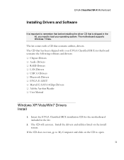
Install the drivers and utilities listed on the CD to load your EVGA Classified SR-X motherboard contains the following software and drivers: Chipset Drivers Audio Drivers RAID Drivers LAN Drivers USB 3.0 Drivers Bluetooth Drivers EVGA E-LEET Marvell E-SATA 6Gbps Drivers Adobe Acrobat Reader User Manual Windows XP/Vista/Win7 Drivers Install 1. EVGA Classified SR-X Motherboard Installing Drivers and Software It is important to remember that before installing the driver CD that is shipped in the kit...
Install the drivers and utilities listed on the CD to load your EVGA Classified SR-X motherboard contains the following software and drivers: Chipset Drivers Audio Drivers RAID Drivers LAN Drivers USB 3.0 Drivers Bluetooth Drivers EVGA E-LEET Marvell E-SATA 6Gbps Drivers Adobe Acrobat Reader User Manual Windows XP/Vista/Win7 Drivers Install 1. EVGA Classified SR-X Motherboard Installing Drivers and Software It is important to remember that before installing the driver CD that is shipped in the kit...

User Guide
Page 32
... of CPU Set up boot strap processor information Set up boot strap processor for POST Enumerate and set up application processors Re-enable cache for boot strap processor Early CPU initialization exit Initialize keyboard controller Detect Mouse Detect Keyboard Test input devices Early POST initialization of chipset registers Relocate System Management interrupt vector Uncompress and initialize BIOS module Initialize devices primary Initialize devices secondary Initialize output devices Allocate memory for ADM module Initialize silent boot module Display...
... of CPU Set up boot strap processor information Set up boot strap processor for POST Enumerate and set up application processors Re-enable cache for boot strap processor Early CPU initialization exit Initialize keyboard controller Detect Mouse Detect Keyboard Test input devices Early POST initialization of chipset registers Relocate System Management interrupt vector Uncompress and initialize BIOS module Initialize devices primary Initialize devices secondary Initialize output devices Allocate memory for ADM module Initialize silent boot module Display...
User Guide
Page 33
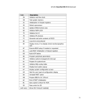
... Update CMOS memory size Initialize NUM-LOCK Initialize Int-13 Initialize IPL devices Generate and write contents of ESCD Log errors encountered Display errors, if no display check monitor/graphics card Execute BIOS setup if needed or requested Late POST initialization of chipset registers Build ACPI tables Program peripheral parameters Initialize system management interrupt Prepare for system boot Initialize IRQ routing table Display boot option popup Display system configuration screen Wait for user input at configuration display...
... Update CMOS memory size Initialize NUM-LOCK Initialize Int-13 Initialize IPL devices Generate and write contents of ESCD Log errors encountered Display errors, if no display check monitor/graphics card Execute BIOS setup if needed or requested Late POST initialization of chipset registers Build ACPI tables Program peripheral parameters Initialize system management interrupt Prepare for system boot Initialize IRQ routing table Display boot option popup Display system configuration screen Wait for user input at configuration display...

User Guide
Page 34
... Lighting HPET - High Precision Event Timer 34 Basic Input Output System CD-ROM - Advanced Configuration and Power Interface BCLK - Floppy Disk Controller FSB - Direct Memory Interface DRAM - Alternate Frame Rendering APIC - For the Win! Hard Disk Drive HDMI - Advanced Programmable Interrupt Controller ACPI - Gigahertz GPU - Alternating Current ACPI - Advanced Configuration and Power Interface AFR - Dual In-line Memory Module DMI - Graphics Processing Unit HDD - Front Side Bus FTW - Complementary Metal-Oxide Semiconductor CPU - Base Clock (or operating frequency...
... Lighting HPET - High Precision Event Timer 34 Basic Input Output System CD-ROM - Advanced Configuration and Power Interface BCLK - Floppy Disk Controller FSB - Direct Memory Interface DRAM - Alternate Frame Rendering APIC - For the Win! Hard Disk Drive HDMI - Advanced Programmable Interrupt Controller ACPI - Gigahertz GPU - Alternating Current ACPI - Advanced Configuration and Power Interface AFR - Dual In-line Memory Module DMI - Graphics Processing Unit HDD - Front Side Bus FTW - Complementary Metal-Oxide Semiconductor CPU - Base Clock (or operating frequency...

User Guide
Page 36
... Interface SFR - Serial Presence Detect SPDIF - System Platform Processors SSD - Universal Serial Bus VDroop - Voltage Regulator 1337 - EVGA Classified SR-X Motherboard POST - This is reserved for the EVGA Elite! 36 Pulse Width Modulation QDR - Redundant Array of Inexpensive Disks RAM - Red Green Blue SATA - Serial Attached SCSI SB - Solid State Drive TCP/IP - Southbridge SCSI - Symmetric Multiprocessing SPD - Transmission Control Protocol/Internet Protocol USB - Video Graphics Array VREG - Quad...
... Interface SFR - Serial Presence Detect SPDIF - System Platform Processors SSD - Universal Serial Bus VDroop - Voltage Regulator 1337 - EVGA Classified SR-X Motherboard POST - This is reserved for the EVGA Elite! 36 Pulse Width Modulation QDR - Redundant Array of Inexpensive Disks RAM - Red Green Blue SATA - Serial Attached SCSI SB - Solid State Drive TCP/IP - Southbridge SCSI - Symmetric Multiprocessing SPD - Transmission Control Protocol/Internet Protocol USB - Video Graphics Array VREG - Quad...

User Guide
Page 37
... right to terminate this document and the software itself (together and separately) is owned, controlled by, licensed to, or used in a particular installation. These limits are subject to ensure compliance with FCC Rules Part 15. EVGA Classified SR-X Motherboard Compliance Information FCC Compliance Information This device complies with FCC regulations. All specifications mentioned in this equipment does cause harmful...
... right to terminate this document and the software itself (together and separately) is owned, controlled by, licensed to, or used in a particular installation. These limits are subject to ensure compliance with FCC Rules Part 15. EVGA Classified SR-X Motherboard Compliance Information FCC Compliance Information This device complies with FCC regulations. All specifications mentioned in this equipment does cause harmful...


