User Guide
Page 3
... SLI Motherboard 1 Before You Begin...7 Parts NOT in the Kit 7 EVGA P55 SLI Motherboard 8 Motherboard Specifications 8 Hardware Installation 10 Safety Instructions 10 Preparing the Motherboard 11 Installing the CPU 11 Installing the CPU Fan 12 Installing System Memory (DIMMs 13 Installing the Motherboard 13 Installing the I/O Shield 14 Securing the Motherboard into a System Case 15 Connecting Cables 15 24-pin ATX Power (PW1 16 8-pin ATX 12V Power (PW12 16 Connecting Serial ATA Cables 16 Connecting Internal Headers 18 Front Panel Header 18 IEEE1394a (Firewire 19 USB Headers...
... SLI Motherboard 1 Before You Begin...7 Parts NOT in the Kit 7 EVGA P55 SLI Motherboard 8 Motherboard Specifications 8 Hardware Installation 10 Safety Instructions 10 Preparing the Motherboard 11 Installing the CPU 11 Installing the CPU Fan 12 Installing System Memory (DIMMs 13 Installing the Motherboard 13 Installing the I/O Shield 14 Securing the Motherboard into a System Case 15 Connecting Cables 15 24-pin ATX Power (PW1 16 8-pin ATX 12V Power (PW12 16 Connecting Serial ATA Cables 16 Connecting Internal Headers 18 Front Panel Header 18 IEEE1394a (Firewire 19 USB Headers...

User Guide
Page 4
...PCI Express x1 Slots 22 PCI Express x16/x8/x4 Slots 22 Onboard Buttons ...23 Clear CMOS Button 23 RESET and POWER Button 23 Post Port Debug LED and LED Status Indicators 24 Post Port Debug LED 24 LED Status Indicators 24 Configuring the BIOS 25 Enter BIOS Setup 26 Main Menu...26 Standard BIOS Features Menu 28 System Time / System Date 29 Advanced BIOS Features 29 IDE Configuration 30 Boot Settings Configuration 30 AHCI Configuration 30 Intel VT-d Configuration 31 USB Configuration 31 Advanced Chipset Features 31 North Bridge Configuration 31 PCI Express Configuration 32 PCI...
...PCI Express x1 Slots 22 PCI Express x16/x8/x4 Slots 22 Onboard Buttons ...23 Clear CMOS Button 23 RESET and POWER Button 23 Post Port Debug LED and LED Status Indicators 24 Post Port Debug LED 24 LED Status Indicators 24 Configuring the BIOS 25 Enter BIOS Setup 26 Main Menu...26 Standard BIOS Features Menu 28 System Time / System Date 29 Advanced BIOS Features 29 IDE Configuration 30 Boot Settings Configuration 30 AHCI Configuration 30 Intel VT-d Configuration 31 USB Configuration 31 Advanced Chipset Features 31 North Bridge Configuration 31 PCI Express Configuration 32 PCI...
User Guide
Page 5
EVGA P55 SLI Motherboard Palette Snooping 35 PCI IDE BusMaster 35 OffBoard PCI/ISA IDE Card 35 Boot Configuration Features 36 Boot Device Priority 36 Hard Disk Drives 36 Power Management Features 37 ACPI Configuration 37 SLP_S4# Min. POST Codes for the EVGA P55 SLI Motherboard 42 Assertion Width 38 Restore on AC Power Loss 38 Hardware Health Configure 38 H/W Health Function 38 CPU Fan Mode Setting 39 Frequency/Voltage Control Menu 39 Memory Configure 39 CPU Configuration 40 Installing Drivers and Software 41 Windows XP/Vista/7 Driver Installation 41 Appendix A.
EVGA P55 SLI Motherboard Palette Snooping 35 PCI IDE BusMaster 35 OffBoard PCI/ISA IDE Card 35 Boot Configuration Features 36 Boot Device Priority 36 Hard Disk Drives 36 Power Management Features 37 ACPI Configuration 37 SLP_S4# Min. POST Codes for the EVGA P55 SLI Motherboard 42 Assertion Width 38 Restore on AC Power Loss 38 Hardware Health Configure 38 H/W Health Function 38 CPU Fan Mode Setting 39 Frequency/Voltage Control Menu 39 Memory Configure 39 CPU Configuration 40 Installing Drivers and Software 41 Windows XP/Vista/7 Driver Installation 41 Appendix A.
User Guide
Page 7
... This kit contains all the necessary parts needed to make the motherboard functional. Intel Socket 1156 Processor DDR3 System Memory Socket 1156 or Socket 775 Cooling fan PCI Express or PCI Graphics Card Power Supply EVGA assumes you will need to reinstall an operating system even though the current hard disk may already have purchased all the hardware necessary to install and connect your new EVGA P55 SLI Motherboard.
... This kit contains all the necessary parts needed to make the motherboard functional. Intel Socket 1156 Processor DDR3 System Memory Socket 1156 or Socket 775 Cooling fan PCI Express or PCI Graphics Card Power Supply EVGA assumes you will need to reinstall an operating system even though the current hard disk may already have purchased all the hardware necessary to install and connect your new EVGA P55 SLI Motherboard.
User Guide
Page 8
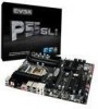
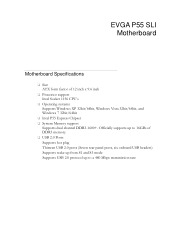
EVGA P55 SLI Motherboard Motherboard Specifications Size ATX form factor of DDR3 memory. USB 2.0 Ports Supports hot plug Thirteen USB 2.0 ports (Seven rear panel ports, six onboard USB headers) Supports wake-up from S1 and S3 mode Supports USB 2.0 protocol up to a 480 Mbps transmission rate Officially supports up to 16GBs of 12 inch x 9.6 inch Processor support Intel Socket 1156 CPU's Operating systems: Supports Windows XP 32bit/64bit, Windows Vista 32bit/64bit, and Windows 7 32bit/64bit Intel P55 Express Chipset System Memory support ...
EVGA P55 SLI Motherboard Motherboard Specifications Size ATX form factor of DDR3 memory. USB 2.0 Ports Supports hot plug Thirteen USB 2.0 ports (Seven rear panel ports, six onboard USB headers) Supports wake-up from S1 and S3 mode Supports USB 2.0 protocol up to a 480 Mbps transmission rate Officially supports up to 16GBs of 12 inch x 9.6 inch Processor support Intel Socket 1156 CPU's Operating systems: Supports Windows XP 32bit/64bit, Windows Vista 32bit/64bit, and Windows 7 32bit/64bit Intel P55 Express Chipset System Memory support ...
User Guide
Page 15
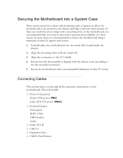
... motherboard using a minimum of nine (9) spacers and screws. 1. Connecting Cables This section takes you remove that the fan assembly is recommended to the I/O shield. 4. Carefully place the motherboard onto the stand offs located inside the chassis. 2. This will include: Power Connections 24-pin ATX power (PW1) 8-pin ATX 12V power (PW12) Internal Headers Front panel IEEE 1394a USB Headers Audio Serial ATA II USB 2.0 Expansion slots CMOS Clear Button Securing the Motherboard into a System Case...
... motherboard using a minimum of nine (9) spacers and screws. 1. Connecting Cables This section takes you remove that the fan assembly is recommended to the I/O shield. 4. Carefully place the motherboard onto the stand offs located inside the chassis. 2. This will include: Power Connections 24-pin ATX power (PW1) 8-pin ATX 12V power (PW12) Internal Headers Front panel IEEE 1394a USB Headers Audio Serial ATA II USB 2.0 Expansion slots CMOS Clear Button Securing the Motherboard into a System Case...
User Guide
Page 18
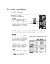
Connecting Internal Headers Front Panel Header The front panel header on this motherboard is one connector used to connect the following four cables. (see Table 2 for pin definitions): PWRLED Attach the front panel power LED cable to these two pins of the case to these two pins. When the system is turned on, the LED is on the connectors to the corresponding pins. PWRSW Attach the power button cable from the front panel of the connector. The HDD indicator...
Connecting Internal Headers Front Panel Header The front panel header on this motherboard is one connector used to connect the following four cables. (see Table 2 for pin definitions): PWRLED Attach the front panel power LED cable to these two pins of the case to these two pins. When the system is turned on, the LED is on the connectors to the corresponding pins. PWRSW Attach the power button cable from the front panel of the connector. The HDD indicator...
User Guide
Page 22
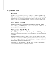
... the chassis back panel with the screw used to accommodate PCIe x1 cards, such as a LAN card, USB card, SCSI card and other cards that comply with PCI specifications. PCI Express x1 Slots There is one PCI Express x1 slot that it is very important to hold the blank cover. For SLI use only slots PCI Express Slots 1 and 2 (primary and secondary) for Graphic Cards and PCI Express x1 and x4 devices. The design of this motherboard supports multiple Graphic Card technology. If the card is...
... the chassis back panel with the screw used to accommodate PCIe x1 cards, such as a LAN card, USB card, SCSI card and other cards that comply with PCI specifications. PCI Express x1 Slots There is one PCI Express x1 slot that it is very important to hold the blank cover. For SLI use only slots PCI Express Slots 1 and 2 (primary and secondary) for Graphic Cards and PCI Express x1 and x4 devices. The design of this motherboard supports multiple Graphic Card technology. If the card is...

User Guide
Page 26
... to select from the list of the screen during the Power On Self Test (POST). Display System Information... Pressing Del takes you to the previous menu, press Esc. To go back to the AMI BIOS CMOS Setup Utility. keys to scroll through the options or press Enter to enter Setup. CMOS Setup Utility - Press F2 to Load Defaults, DEL to display the associated submenu. Use the + and - Enter BIOS Setup The BIOS is critical to maintain...
... to select from the list of the screen during the Power On Self Test (POST). Display System Information... Pressing Del takes you to the previous menu, press Esc. To go back to the AMI BIOS CMOS Setup Utility. keys to scroll through the options or press Enter to enter Setup. CMOS Setup Utility - Press F2 to Load Defaults, DEL to display the associated submenu. Use the + and - Enter BIOS Setup The BIOS is critical to maintain...
User Guide
Page 27
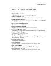
... Chipset Features Use this menu to set up onboard peripherals such as IDE, RAID, USB, LAN, and MAC control. PCI/PNP Resource Management Use this menu to configure resource management. Boot Configuration Features Use this menu to modify the system's boot configuration. Power Management Features Use this menu to modify power management, power on, and sleep features. Hardware Health Configure Use this menu to view system vitals. Frequency/Voltage Control Use this menu to optimize system performance and configure clocks, voltages, memory timings...
... Chipset Features Use this menu to set up onboard peripherals such as IDE, RAID, USB, LAN, and MAC control. PCI/PNP Resource Management Use this menu to configure resource management. Boot Configuration Features Use this menu to modify the system's boot configuration. Power Management Features Use this menu to modify power management, power on, and sleep features. Hardware Health Configure Use this menu to view system vitals. Frequency/Voltage Control Use this menu to optimize system performance and configure clocks, voltages, memory timings...

User Guide
Page 30
... Removable Boot Device Priority Move Enter:Select +/-/:Value F10:Save ESC:Exit F1:General Help F5:Previous Values F7:Optimized Defaults Figure 4. Please note for new system installations. AHCI Configuration This menu will allow you to change advanced AHCI settings, such as Bootup Num-Lock status, Quiet Boot and other advanced features. Advanced BIOS Features IDE Configuration Use this option to enable RAID or switch between IDE and AHCI mode. status and more. Boot Settings Configuration Use this...
... Removable Boot Device Priority Move Enter:Select +/-/:Value F10:Save ESC:Exit F1:General Help F5:Previous Values F7:Optimized Defaults Figure 4. Please note for new system installations. AHCI Configuration This menu will allow you to change advanced AHCI settings, such as Bootup Num-Lock status, Quiet Boot and other advanced features. Advanced BIOS Features IDE Configuration Use this option to enable RAID or switch between IDE and AHCI mode. status and more. Boot Settings Configuration Use this...

User Guide
Page 31
... Controller [Enabled] LAN2 Controller [Enabled] LAN Boot [Disabled] ESATA Controller [Enabled] ESATA Boot [Disabled] PE1 Slot [Auto] P80 Show CPU Temperature Slot[Enabled] ME Subsystem Configuration [Press Enter] Move Enter:Select +/-/:Value F10:Save ESC:Exit F1:General Help F5:Previous Values F7:Optimized Defaults Figure 5. Advanced Chipset Settings WARNING: Setting wrong values in below sections may cause system to enable Legacy USB support, force USB 1.1 mode and more . Advanced Chipset Features Select Advanced Chipset Features from the CMOS Setup Utility menu...
... Controller [Enabled] LAN2 Controller [Enabled] LAN Boot [Disabled] ESATA Controller [Enabled] ESATA Boot [Disabled] PE1 Slot [Auto] P80 Show CPU Temperature Slot[Enabled] ME Subsystem Configuration [Press Enter] Move Enter:Select +/-/:Value F10:Save ESC:Exit F1:General Help F5:Previous Values F7:Optimized Defaults Figure 5. Advanced Chipset Settings WARNING: Setting wrong values in below sections may cause system to enable Legacy USB support, force USB 1.1 mode and more . Advanced Chipset Features Select Advanced Chipset Features from the CMOS Setup Utility menu...

User Guide
Page 32
... Network Controller, such as Payload size. It is enabled the onboard Post Port LED will allow you to set the onboard audio function. PCI Express Configuration This option menu will allow you to enable/disable the Intel VT-d feature. Intel VT-d Configuration This option will display the CPU temperature. It is recommended to leave this enabled, unless you are as follows: HD Audio Controller Use this function to set advanced PCI Express options, such as an EVGA Killer Xeno card. ESATA Controller...
... Network Controller, such as Payload size. It is enabled the onboard Post Port LED will allow you to set the onboard audio function. PCI Express Configuration This option menu will allow you to enable/disable the Intel VT-d feature. Intel VT-d Configuration This option will display the CPU temperature. It is recommended to leave this enabled, unless you are as follows: HD Audio Controller Use this function to set advanced PCI Express options, such as an EVGA Killer Xeno card. ESATA Controller...

User Guide
Page 34
... the CMOS Setup Utility menu and press Enter to PCI VGA Palette Snooping PCI IDE BusMaster OffBoard PCI/ISA IDE Card IRQ3 IRQ4 IRQ5 IRQ7 IRQ9 IRQ10 [No] [No] [64] [Yes] [Disabled] [Enabled] [Auto] [Available] [Available] [Available] [Available] [Available] [Available] Move Enter:Select +/-/:Value F10:Save ESC:Exit F1:General Help F5:Previous Values F7:Optimized Defaults Figure 6. Clear NVRAM Plug & Play O/S PCI Latency Timer Allocate IRQ to display the advanced settings. PCI...
... the CMOS Setup Utility menu and press Enter to PCI VGA Palette Snooping PCI IDE BusMaster OffBoard PCI/ISA IDE Card IRQ3 IRQ4 IRQ5 IRQ7 IRQ9 IRQ10 [No] [No] [64] [Yes] [Disabled] [Enabled] [Auto] [Available] [Available] [Available] [Available] [Available] [Available] Move Enter:Select +/-/:Value F10:Save ESC:Exit F1:General Help F5:Previous Values F7:Optimized Defaults Figure 6. Clear NVRAM Plug & Play O/S PCI Latency Timer Allocate IRQ to display the advanced settings. PCI...

User Guide
Page 36
Boot Configuration Features Select Boot Configuration Features from the CMOS Setup Utility menu and press Enter to display the settings. Boot Device Priority Hard Disk Drives CD/DVD Drives [Press Enter] [Press Enter] [Press Enter] Help Item Specifies the Boot Device Priority sequence. Boot Configuration Features Boot Device Priority This option menu will allow specification of the Hard Disk boot priority sequence. Move Enter:Select +/-/:Value F10:Save ESC:Exit F1:General Help F5:Previous Values F7:Optimized Defaults Move Enter:Select +/-/PU/PD...
Boot Configuration Features Select Boot Configuration Features from the CMOS Setup Utility menu and press Enter to display the settings. Boot Device Priority Hard Disk Drives CD/DVD Drives [Press Enter] [Press Enter] [Press Enter] Help Item Specifies the Boot Device Priority sequence. Boot Configuration Features Boot Device Priority This option menu will allow specification of the Hard Disk boot priority sequence. Move Enter:Select +/-/:Value F10:Save ESC:Exit F1:General Help F5:Previous Values F7:Optimized Defaults Move Enter:Select +/-/PU/PD...

User Guide
Page 37
.../DVD boot priority sequence. Assertion Width [4 to display the settings. Configuring the BIOS CD/DVD Drives This option menu allows you specification of Advanced ACPI configurations. Power Management Features Select Power Management Features from the CMOS Setup Utility menu and press Enter to 5 seconds] Restore on AC Power Loss [Power Off] Help Item Section for Advanced ACPI Configuration. Move Enter:Select +/-/:Value F10:Save ESC:Exit F1:General Help F5:Previous Values F7:Optimized Defaults...
.../DVD boot priority sequence. Assertion Width [4 to display the settings. Configuring the BIOS CD/DVD Drives This option menu allows you specification of Advanced ACPI configurations. Power Management Features Select Power Management Features from the CMOS Setup Utility menu and press Enter to 5 seconds] Restore on AC Power Loss [Power Off] Help Item Section for Advanced ACPI Configuration. Move Enter:Select +/-/:Value F10:Save ESC:Exit F1:General Help F5:Previous Values F7:Optimized Defaults...

User Guide
Page 38
... width. Hardware Health Configure H/W Health Function [Enabled] CPU Temperature Sensor VREG Temperature Sensor System Temperature Sensor :34C/93F :48C/118F :34C/93F CPU Fan Speed Power Fan Speed Chassis Fan Speed :3264 RPM :1337 RPM :3864 RPM VCore Memory CPU VTT PCH +5V :1.337 V :1.481 V :1.021 V :1.031 V :4.961 V Help Item Enables Hardware Health Monitoring Device. Hardware Health Configure H/W Health Function This will enable or disable Hardware Health Monitoring. SLP_S4# Min. Move Enter:Select +/-/:Value F10...
... width. Hardware Health Configure H/W Health Function [Enabled] CPU Temperature Sensor VREG Temperature Sensor System Temperature Sensor :34C/93F :48C/118F :34C/93F CPU Fan Speed Power Fan Speed Chassis Fan Speed :3264 RPM :1337 RPM :3864 RPM VCore Memory CPU VTT PCH +5V :1.337 V :1.481 V :1.021 V :1.031 V :4.961 V Help Item Enables Hardware Health Monitoring Device. Hardware Health Configure H/W Health Function This will enable or disable Hardware Health Monitoring. SLP_S4# Min. Move Enter:Select +/-/:Value F10...
User Guide
Page 39
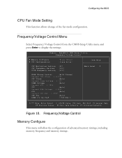
... PCH Voltage : 1.050V PCH [Auto] Current CPU PLL : 1.800V CPU PLL [Auto] DIMM 1/2 DQ Vref [ 849 KHz ] Item Help Main Level Move Enter:Select +/-/PU/PD:Value F10:Save ESC:Exit F1:General Help F5:Previous Values F6:Fail-Safe Defaults F7:Optimized Defaults Figure 10. Frequency/Voltage Control Memory Configure This menu will allow the configuration of the fan mode configuration. Frequency/Voltage Control Menu Select Frequency/Voltage Control from the CMOS Setup Utility menu and press Enter to display the settings.
... PCH Voltage : 1.050V PCH [Auto] Current CPU PLL : 1.800V CPU PLL [Auto] DIMM 1/2 DQ Vref [ 849 KHz ] Item Help Main Level Move Enter:Select +/-/PU/PD:Value F10:Save ESC:Exit F1:General Help F5:Previous Values F6:Fail-Safe Defaults F7:Optimized Defaults Figure 10. Frequency/Voltage Control Memory Configure This menu will allow the configuration of the fan mode configuration. Frequency/Voltage Control Menu Select Frequency/Voltage Control from the CMOS Setup Utility menu and press Enter to display the settings.
User Guide
Page 41
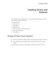
Configuring the BIOS Installing Drivers and Software The CD that has been shipped with the EVGA P55 SLI Motherboard contains the following software and drivers: Chipset Drivers Audio drivers LAN Drivers RAID Drivers EVGA E-LEET Overclocking Utility Adobe Acrobat Reader User's Manual Windows XP/Vista/7 Driver Installation 5. Insert the Intel P55 installation CD for the motherboard included in the kit. 6. The CD will autorun, install the drivers and utilities listed on the CD to My Computer and click...
Configuring the BIOS Installing Drivers and Software The CD that has been shipped with the EVGA P55 SLI Motherboard contains the following software and drivers: Chipset Drivers Audio drivers LAN Drivers RAID Drivers EVGA E-LEET Overclocking Utility Adobe Acrobat Reader User's Manual Windows XP/Vista/7 Driver Installation 5. Insert the Intel P55 installation CD for the motherboard included in the kit. 6. The CD will autorun, install the drivers and utilities listed on the CD to My Computer and click...
User Guide
Page 42
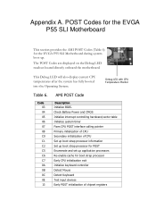
... EVGA P55 SLI Motherboard during system boot up application processors Re-enable cache for POST Enumerate and set up . Debug LED with CPU Temperature Monitor Table 6. Check Battery Power and CMOS Initialize interrupt controlling hardware/vector table Initialize system timer Fixes CPU POST interface calling pointer Primary initialization of CPU Secondary initialization of CPU Set up boot strap processor information Set up boot strap processor for boot strap processor Early CPU initialization exit Initialize keyboard controller Detect Mouse Detect Keyboard Test input devices Early POST...
... EVGA P55 SLI Motherboard during system boot up application processors Re-enable cache for POST Enumerate and set up . Debug LED with CPU Temperature Monitor Table 6. Check Battery Power and CMOS Initialize interrupt controlling hardware/vector table Initialize system timer Fixes CPU POST interface calling pointer Primary initialization of CPU Secondary initialization of CPU Set up boot strap processor information Set up boot strap processor for boot strap processor Early CPU initialization exit Initialize keyboard controller Detect Mouse Detect Keyboard Test input devices Early POST...


