Owner's Manual
Page 5
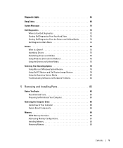
Diagnostic Lights 66 Beep Codes 69 System Messages 70 Dell Diagnostics 72 When to Use Dell Diagnostics 72 Starting Dell Diagnostics From Your Hard Drive 72 Starting Dell Diagnostics From the Drivers and Utilities Media 73 Dell Diagnostics Main Menu 74 Drivers 75 What Is a Driver 75 ... Operating System 78 Using Microsoft Windows System Restore 78 Using Dell PC Restore and Dell Factory Image Restore 79 Using the Operating System Media 82 Troubleshooting Software and Hardware Problems 83 5 Removing and Installing Parts 85 Before You Begin 85 Recommended Tools 85 Preparing to...
Diagnostic Lights 66 Beep Codes 69 System Messages 70 Dell Diagnostics 72 When to Use Dell Diagnostics 72 Starting Dell Diagnostics From Your Hard Drive 72 Starting Dell Diagnostics From the Drivers and Utilities Media 73 Dell Diagnostics Main Menu 74 Drivers 75 What Is a Driver 75 ... Operating System 78 Using Microsoft Windows System Restore 78 Using Dell PC Restore and Dell Factory Image Restore 79 Using the Operating System Media 82 Troubleshooting Software and Hardware Problems 83 5 Removing and Installing Parts 85 Before You Begin 85 Recommended Tools 85 Preparing to...

Owner's Manual
Page 53
...157). Troubleshooting Solving Problems Follow these tips when you troubleshoot your Dell™ computer to the Windows Classic view. Discard used batteries according to the manufacturer's instructions. R E P L A C E T H E B A T T E R Y - Windows XP: • Click Start and click My Computer. Troubleshooting 53... CAUTION: Before you added or removed a part before the problem started, review the installation procedures and ensure that the part is correctly installed. • If a peripheral device does not work properly, contact Dell (see "Replacing the Battery" on the ...
...157). Troubleshooting Solving Problems Follow these tips when you troubleshoot your Dell™ computer to the Windows Classic view. Discard used batteries according to the manufacturer's instructions. R E P L A C E T H E B A T T E R Y - Windows XP: • Click Start and click My Computer. Troubleshooting 53... CAUTION: Before you added or removed a part before the problem started, review the installation procedures and ensure that the part is correctly installed. • If a peripheral device does not work properly, contact Dell (see "Replacing the Battery" on the ...
Owner's Manual
Page 74
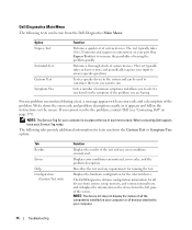
... test and any error conditions encountered. If you are having. Displays error conditions encountered, error codes, and the problem description. The Dell Diagnostics obtains configuration information for all devices attached to 20 minutes and requires no interaction on your Service Tag ready. Performs a thorough...The test typically takes 10 to your computer. 74 Troubleshooting For any requirements for the selected device. When contacting Dell support, have your part. NOTE: The device list may not display the names of the problem you cannot resolve the problem, contact...
... test and any error conditions encountered. If you are having. Displays error conditions encountered, error codes, and the problem description. The Dell Diagnostics obtains configuration information for all devices attached to 20 minutes and requires no interaction on your Service Tag ready. Performs a thorough...The test typically takes 10 to your computer. 74 Troubleshooting For any requirements for the selected device. When contacting Dell support, have your part. NOTE: The device list may not display the names of the problem you cannot resolve the problem, contact...
Owner's Manual
Page 85
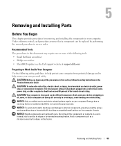
... component can be replaced by its metal mounting bracket. Removing and Installing Parts 85 NOTICE: Handle components and cards with care. Unless otherwise noted, each procedure assumes that is not authorized by Dell is heavy and can be difficult to internal components, ground yourself by ...To avoid electrostatic discharge and damage to maneuver. Do not touch the components or contacts on your computer. Removing and Installing Parts Before You Begin This chapter provides procedures for removing and installing the components in reverse order. The total ampere rating of ...
... component can be replaced by its metal mounting bracket. Removing and Installing Parts 85 NOTICE: Handle components and cards with care. Unless otherwise noted, each procedure assumes that is not authorized by Dell is heavy and can be difficult to internal components, ground yourself by ...To avoid electrostatic discharge and damage to maneuver. Do not touch the components or contacts on your computer. Removing and Installing Parts Before You Begin This chapter provides procedures for removing and installing the components in reverse order. The total ampere rating of ...

Owner's Manual
Page 86
... position. 6 With the help of cable, press inward on the cover release latch. 86 Removing and Installing Parts Removing the Computer Cover CAUTION: Before you shut down the operating system: • In Windows XP, click Start→ Turn Off Computer→ Turn off after the operating system shutdown process is complete. 3 Ensure...
... position. 6 With the help of cable, press inward on the cover release latch. 86 Removing and Installing Parts Removing the Computer Cover CAUTION: Before you shut down the operating system: • In Windows XP, click Start→ Turn Off Computer→ Turn off after the operating system shutdown process is complete. 3 Ensure...

Owner's Manual
Page 87
Removing and Installing Parts 87 NOTICE: Ensure that sufficient space exists to support the removed cover-at least 30 centimeters (1 foot) of desktop space. 1 2 3 4 1 computer cover 4 stabilizing feet (closed) 2 cover release latch 3 cover hinge tabs 3 With the cover release latch pulled back, grip the sides of the cover, then pivot the top of the cover up and away from the computer. 4 Slide the cover forward and up to remove it from the hinge slots, then set it aside in a secure and protected location.
Removing and Installing Parts 87 NOTICE: Ensure that sufficient space exists to support the removed cover-at least 30 centimeters (1 foot) of desktop space. 1 2 3 4 1 computer cover 4 stabilizing feet (closed) 2 cover release latch 3 cover hinge tabs 3 With the cover release latch pulled back, grip the sides of the cover, then pivot the top of the cover up and away from the computer. 4 Slide the cover forward and up to remove it from the hinge slots, then set it aside in a secure and protected location.

Owner's Manual
Page 88
Inside View of Your Computer 3 2 1 5 1 optical drive bays (4) 4 card fan 4 2 floppy drive/media card reader 5 front fan 3 hard drive bays (4) 88 Removing and Installing Parts
Inside View of Your Computer 3 2 1 5 1 optical drive bays (4) 4 card fan 4 2 floppy drive/media card reader 5 front fan 3 hard drive bays (4) 88 Removing and Installing Parts
Owner's Manual
Page 89
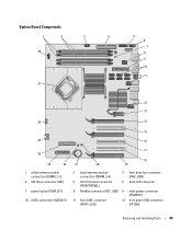
System Board Components 1 2 3 4 28 27 5 6 7 8 9 10 11 12 13 26 14 15 25 16 24 23 22 1 white memory module connectors (DIMM_1-2) 4 IDE drive connector (IDE) 7 power button (PWR_BT) 10 SATA connectors (SATA0-5) 17 21 20 18 19 2 black memory module connectors (DIMM_3-4) 3 hard drive fan connector (FAN_HDD) 5 front I/O panel connector (FRONTPANEL) 6 back LED connector 8 FlexBay connector (INT_USB) 9 main power connector (POWER1) 11 front USB connector (FRNT_USB) 12 front panel 1394 connector (FP1394) Removing and Installing Parts 89
System Board Components 1 2 3 4 28 27 5 6 7 8 9 10 11 12 13 26 14 15 25 16 24 23 22 1 white memory module connectors (DIMM_1-2) 4 IDE drive connector (IDE) 7 power button (PWR_BT) 10 SATA connectors (SATA0-5) 17 21 20 18 19 2 black memory module connectors (DIMM_3-4) 3 hard drive fan connector (FAN_HDD) 5 front I/O panel connector (FRONTPANEL) 6 back LED connector 8 FlexBay connector (INT_USB) 9 main power connector (POWER1) 11 front USB connector (FRNT_USB) 12 front panel 1394 connector (FP1394) Removing and Installing Parts 89
Owner's Manual
Page 90
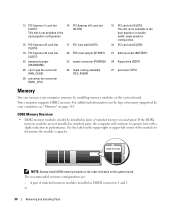
... Memory Overview • DDR2 memory modules should be installed in pairs of matched memory modules installed in DIMM connectors 1 and 2 or 90 Removing and Installing Parts
... Memory Overview • DDR2 memory modules should be installed in pairs of matched memory modules installed in DIMM connectors 1 and 2 or 90 Removing and Installing Parts
Owner's Manual
Page 91
... A matched pair of modules in any new modules that you install modules in DIMM connectors 1 B matched pair of memory. NOTE: Memory purchased from Dell. If you are using a 64-bit operating system, your computer will support a maximum of 4 GB of memory modules in DIMM and 2 (white ... a single memory module in DIMM connector 1, the connector closest to the processor, before you may not start properly. Removing and Installing Parts 91 A pair of matched memory modules installed in DIMM connectors 1 and 2 and another matched pair installed in DIMM connectors 1 and 2 or ...
... A matched pair of modules in any new modules that you install modules in DIMM connectors 1 B matched pair of memory. NOTE: Memory purchased from Dell. If you are using a 64-bit operating system, your computer will support a maximum of 4 GB of memory modules in DIMM and 2 (white ... a single memory module in DIMM connector 1, the connector closest to the processor, before you may not start properly. Removing and Installing Parts 91 A pair of matched memory modules installed in DIMM connectors 1 and 2 and another matched pair installed in DIMM connectors 1 and 2 or ...

Owner's Manual
Page 92
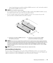
... notch on the bottom of the procedures in this section, follow the safety instructions in the connector. 3 2 1 1 cutouts (2) 4 crossbar 2 memory module 92 Removing and Installing Parts 4 3 notch Installing Memory CAUTION: Before you begin any of the module with the crossbar in the Product Information Guide.
... notch on the bottom of the procedures in this section, follow the safety instructions in the connector. 3 2 1 1 cutouts (2) 4 crossbar 2 memory module 92 Removing and Installing Parts 4 3 notch Installing Memory CAUTION: Before you begin any of the module with the crossbar in the Product Information Guide.

Owner's Manual
Page 93
.... NOTICE: To connect a network cable, first plug the cable into the network port or device and then plug it from the connector. Removing and Installing Parts 93 NOTICE: To avoid electrostatic discharge and damage to internal components, ground yourself by using a wrist grounding strap or by periodically touching an unpainted metal...
.... NOTICE: To connect a network cable, first plug the cable into the network port or device and then plug it from the connector. Removing and Installing Parts 93 NOTICE: To avoid electrostatic discharge and damage to internal components, ground yourself by using a wrist grounding strap or by periodically touching an unpainted metal...

Owner's Manual
Page 94
... use. 1 2 5 3 1 PCI card 4 PCI Express x1 card slot 2 PCI Express x16 card 5 PCI Express x1 card 4 3 PCI Express x16 card slot 94 Removing and Installing Parts Cards CAUTION: Before you begin any of the PCI Express x16 card slots in the Product Information Guide.
... use. 1 2 5 3 1 PCI card 4 PCI Express x1 card slot 2 PCI Express x16 card 5 PCI Express x1 card 4 3 PCI Express x16 card slot 94 Removing and Installing Parts Cards CAUTION: Before you begin any of the PCI Express x16 card slots in the Product Information Guide.

Owner's Manual
Page 95
... "Removing a PCI Express Graphics Card from a Dual Configuration" on page 100 to the card. 1 2 3 1 release tab 4 fan bracket 4 2 card retainer 3 alignment guide Removing and Installing Parts 95 however, the card is not necessary when installing additional graphics cards; Removing PCI and PCI Express Cards NOTICE: To avoid electrostatic discharge and damage...
... "Removing a PCI Express Graphics Card from a Dual Configuration" on page 100 to the card. 1 2 3 1 release tab 4 fan bracket 4 2 card retainer 3 alignment guide Removing and Installing Parts 95 however, the card is not necessary when installing additional graphics cards; Removing PCI and PCI Express Cards NOTICE: To avoid electrostatic discharge and damage...

Owner's Manual
Page 96
... system board connector as you removed a sound card or a network adapter, see "Network Adapter and Sound Card Settings" on page 105. 96 Removing and Installing Parts NOTICE: Do not route card cables over the installed cards and snap it into place, ensure that lays over or behind the cards. NOTE: If...
... system board connector as you removed a sound card or a network adapter, see "Network Adapter and Sound Card Settings" on page 105. 96 Removing and Installing Parts NOTICE: Do not route card cables over the installed cards and snap it into place, ensure that lays over or behind the cards. NOTE: If...

Owner's Manual
Page 97
... the appropriate card slot and pivot the card retainer back through the chassis wall. 1 2 3 1 release tab 4 fan bracket 4 2 card retainer 3 alignment guide Removing and Installing Parts 97
... the appropriate card slot and pivot the card retainer back through the chassis wall. 1 2 3 1 release tab 4 fan bracket 4 2 card retainer 3 alignment guide Removing and Installing Parts 97

Owner's Manual
Page 98
... that you may damage the system board. 8 Gently pull the securing tab (if present) and place the card in the slot. 98 Removing and Installing Parts If the card is full length, insert the card guide into the alignment slot on the fan bracket. 1 2 3 1 PCI Express x16 card 2 securing tab 3 PCI...
... that you may damage the system board. 8 Gently pull the securing tab (if present) and place the card in the slot. 98 Removing and Installing Parts If the card is full length, insert the card guide into the alignment slot on the fan bracket. 1 2 3 1 PCI Express x16 card 2 securing tab 3 PCI...

Owner's Manual
Page 99
... flush with the alignment bar and the notch in degraded graphics performance. 9 Connect any cables that lays over or behind the cards. Removing and Installing Parts 99 2 3 1 6 4 5 1 card connector (seated) 4 bracket improperly aligned outside of slot 2 card connector (not seated) 5 alignment bar 3 bracket properly aligned within slot 6 alignment guide NOTICE: Do...
... flush with the alignment bar and the notch in degraded graphics performance. 9 Connect any cables that lays over or behind the cards. Removing and Installing Parts 99 2 3 1 6 4 5 1 card connector (seated) 4 bracket improperly aligned outside of slot 2 card connector (not seated) 5 alignment bar 3 bracket properly aligned within slot 6 alignment guide NOTICE: Do...

Owner's Manual
Page 100
13 Install any other hand by pulling it aside. 1 2 3 1 graphics card bridge 2 power connectors (2) 3 dual-PCI Express graphics cards 100 Removing and Installing Parts NOTE: If you installed a sound card or a network adapter, see "Removing PCI and PCI Express Cards" on page 95. 1 Follow the procedures in the card ...
13 Install any other hand by pulling it aside. 1 2 3 1 graphics card bridge 2 power connectors (2) 3 dual-PCI Express graphics cards 100 Removing and Installing Parts NOTE: If you installed a sound card or a network adapter, see "Removing PCI and PCI Express Cards" on page 95. 1 Follow the procedures in the card ...

Owner's Manual
Page 101
NOTE: If the card is full length, press the release tab on the end of the alignment guides on the system board connector as you grasp the card by its top corners, and then ease the card out of the card retainer at the appropriate card slot and pivot the card retainer back through the chassis wall. 1 2 3 1 release tab 4 fan bracket 4 2 card retainer 3 alignment guide 7 Press the release tab (if present) on the fan bracket. Removing and Installing Parts 101 5 Disconnect any cables connected to the card. 6 Press down the tab on the top of the connector.
NOTE: If the card is full length, press the release tab on the end of the alignment guides on the system board connector as you grasp the card by its top corners, and then ease the card out of the card retainer at the appropriate card slot and pivot the card retainer back through the chassis wall. 1 2 3 1 release tab 4 fan bracket 4 2 card retainer 3 alignment guide 7 Press the release tab (if present) on the fan bracket. Removing and Installing Parts 101 5 Disconnect any cables connected to the card. 6 Press down the tab on the top of the connector.


