Owner's Manual
Page 4
Transferring Information to a New Computer 43 Power Management Options in Windows XP 44 Standby Mode 44 Hibernate Mode 45 Power Options Properties 45 Power Management Options...47 Configuring Power Management Settings 47 2 Optimizing for Greater Performance 49 Understanding Dual-Graphics Technology 49 Understanding CPU Overclocking 49 3 Dell™ QuickSet 51 4 Troubleshooting 53 Solving Problems 53 Battery Problems 53 Drive Problems 53 E-Mail, Modem, and Internet Problems... Problems 62 Sound and Speaker Problems 63 Video and Monitor Problems 63 Power Lights 65 4 Contents
Transferring Information to a New Computer 43 Power Management Options in Windows XP 44 Standby Mode 44 Hibernate Mode 45 Power Options Properties 45 Power Management Options...47 Configuring Power Management Settings 47 2 Optimizing for Greater Performance 49 Understanding Dual-Graphics Technology 49 Understanding CPU Overclocking 49 3 Dell™ QuickSet 51 4 Troubleshooting 53 Solving Problems 53 Battery Problems 53 Drive Problems 53 E-Mail, Modem, and Internet Problems... Problems 62 Sound and Speaker Problems 63 Video and Monitor Problems 63 Power Lights 65 4 Contents
Owner's Manual
Page 5
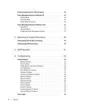
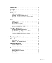
Diagnostic Lights 66 Beep Codes 69 System Messages 70 Dell Diagnostics 72 When to Use Dell Diagnostics 72 Starting Dell Diagnostics From Your Hard Drive 72 Starting Dell Diagnostics From the Drivers and Utilities Media 73 Dell Diagnostics Main Menu 74 Drivers 75 What Is a Driver 75 Identifying ...76 Using the Drivers and Utilities Media 76 Restoring Your Operating System 78 Using Microsoft Windows System Restore 78 Using Dell PC Restore and Dell Factory Image Restore 79 Using the Operating System Media 82 Troubleshooting Software and Hardware Problems 83 5 Removing and Installing...
Diagnostic Lights 66 Beep Codes 69 System Messages 70 Dell Diagnostics 72 When to Use Dell Diagnostics 72 Starting Dell Diagnostics From Your Hard Drive 72 Starting Dell Diagnostics From the Drivers and Utilities Media 73 Dell Diagnostics Main Menu 74 Drivers 75 What Is a Driver 75 Identifying ...76 Using the Drivers and Utilities Media 76 Restoring Your Operating System 78 Using Microsoft Windows System Restore 78 Using Dell PC Restore and Dell Factory Image Restore 79 Using the Operating System Media 82 Troubleshooting Software and Hardware Problems 83 5 Removing and Installing...

Owner's Manual
Page 14
...LEDs can also be installed at all times to indicate different states: • No light - The power light illuminates and blinks or remains solid to ensure maximum system stability. CAUTION: The computer.... NOTE: The color of the front panel LEDs can be adjusted in system setup (see "Dell Diagnostics" on page 15). NOTE: The power button can be a problem with your computer (see...computer is ejected. There may exist. NOTICE: To avoid losing data, do not use in Windows XP" on page 166). Failure to install the stand could result in the computer tipping over, potentially ...
...LEDs can also be installed at all times to indicate different states: • No light - The power light illuminates and blinks or remains solid to ensure maximum system stability. CAUTION: The computer.... NOTE: The color of the front panel LEDs can be adjusted in system setup (see "Dell Diagnostics" on page 15). NOTE: The power button can be a problem with your computer (see...computer is ejected. There may exist. NOTICE: To avoid losing data, do not use in Windows XP" on page 166). Failure to install the stand could result in the computer tipping over, potentially ...
Owner's Manual
Page 15
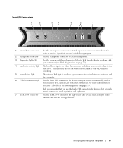
... "Boot Sequence" on page 173. Setting Up and Using Your Computer 15 For more information on bootable USB devices see "Dell Diagnostics" on page 72). 4 hard-drive activity light The hard drive light is on when a good connection exists between a network and the computer. 6 USB 2.0 connectors (2) Use the front USB connectors for devices...
... "Boot Sequence" on page 173. Setting Up and Using Your Computer 15 For more information on bootable USB devices see "Dell Diagnostics" on page 72). 4 hard-drive activity light The hard drive light is on when a good connection exists between a network and the computer. 6 USB 2.0 connectors (2) Use the front USB connectors for devices...

Owner's Manual
Page 16
The appearance of the computer. Plug USB and other devices into the appropriate connectors (see "System Setup" on page 166). Multi-colored lights provide illumination for any installed PCI or PCI Express cards. NOTE: The color of the back panel LEDs can be adjusted in system setup (see "...
The appearance of the computer. Plug USB and other devices into the appropriate connectors (see "System Setup" on page 166). Multi-colored lights provide illumination for any installed PCI or PCI Express cards. NOTE: The color of the back panel LEDs can be adjusted in system setup (see "...

Owner's Manual
Page 17
...use Category 5 wiring and connectors for your computer to the computer. Setting Up and Using Your Computer 17 Flashes a yellow light when the computer is not detecting a physical connection to attach your network. Plug a standard PS/2 keyboard into the network ...a standard PS/2 mouse into a USB connector. A good connection exists between a 10-Mbps network and the computer. • Orange - NOTE: Dell recommends that the network cable has been securely attached. Use the network adapter connector to the network. Back I/O Connectors 1 23 4 5 6 7 8...
...use Category 5 wiring and connectors for your computer to the computer. Setting Up and Using Your Computer 17 Flashes a yellow light when the computer is not detecting a physical connection to attach your network. Plug a standard PS/2 keyboard into the network ...a standard PS/2 mouse into a USB connector. A good connection exists between a 10-Mbps network and the computer. • Orange - NOTE: Dell recommends that the network cable has been securely attached. Use the network adapter connector to the network. Back I/O Connectors 1 23 4 5 6 7 8...

Owner's Manual
Page 51
For more information about QuickSet, right-click the QuickSet icon and select Help. Dell™ QuickSet 51 The taskbar is located in the Microsoft® Windows® taskbar. You can start QuickSet by either clicking, double-clicking, or right-clicking the QuickSet icon in the lower-right corner of your computer. Dell™ QuickSet allows you to select and adjust LED light effects, also known as LightFX™. Dell™ QuickSet NOTE: This feature may not be available on your screen.
For more information about QuickSet, right-click the QuickSet icon and select Help. Dell™ QuickSet 51 The taskbar is located in the Microsoft® Windows® taskbar. You can start QuickSet by either clicking, double-clicking, or right-clicking the QuickSet icon in the lower-right corner of your computer. Dell™ QuickSet allows you to select and adjust LED light effects, also known as LightFX™. Dell™ QuickSet NOTE: This feature may not be available on your screen.

Owner's Manual
Page 58
...8594; Programs→ Use an older program with this section, follow the safety instructions in an environment similar to non-XP operating system environments. 1 Click Start→ All Programs→ Accessories→ Program Compatibility Wizard→ Next. 2 ... simultaneously to access the Task Manager. 2 Click the Applications tab. 3 Click to get a response by pressing a key on a floppy disk, CD, or DVD. See "Diagnostic Lights" on the screen. 58 Troubleshooting C H E C K T H E S O F T W A R E D O C U M E N T A T I G H T S - If necessary, uninstall and then reinstall ...
...8594; Programs→ Use an older program with this section, follow the safety instructions in an environment similar to non-XP operating system environments. 1 Click Start→ All Programs→ Accessories→ Program Compatibility Wizard→ Next. 2 ... simultaneously to access the Task Manager. 2 Click the Applications tab. 3 Click to get a response by pressing a key on a floppy disk, CD, or DVD. See "Diagnostic Lights" on the screen. 58 Troubleshooting C H E C K T H E S O F T W A R E D O C U M E N T A T I G H T S - If necessary, uninstall and then reinstall ...

Owner's Manual
Page 60
Windows XP 1 Click Start→ Control Panel→ Mouse. 2 Adjust the settings as shown on the setup diagram for bent or broken pins. R U N T H E H A R D W A R E TR O U B L E S H O O T... firmly inserted into the network connector on the computer. and down or Turn Off, and then press . 3 After the computer turns off (see "Controls and Lights" on page 83. 60 Troubleshooting C H E C K T H E N E T W O R K C A B L E C O N N E C T O R - R U N T H E H A R D W A R E TR O U B L E S H O O T E R - RESTART THE COMPUTER - 1 Simultaneously press to display the Start menu. 2 Press , press ...
Windows XP 1 Click Start→ Control Panel→ Mouse. 2 Adjust the settings as shown on the setup diagram for bent or broken pins. R U N T H E H A R D W A R E TR O U B L E S H O O T... firmly inserted into the network connector on the computer. and down or Turn Off, and then press . 3 After the computer turns off (see "Controls and Lights" on page 83. 60 Troubleshooting C H E C K T H E N E T W O R K C A B L E C O N N E C T O R - R U N T H E H A R D W A R E TR O U B L E S H O O T E R - RESTART THE COMPUTER - 1 Simultaneously press to display the Start menu. 2 Press , press ...
Owner's Manual
Page 61
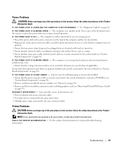
... be malfunctioning or incorrectly installed. • Ensure that the processor power cable is set to verify that the computer turns on page 89). See "Diagnostic Lights" on page 95). The computer is either turned off or is working by testing it with another device, such as a lamp. • Ensure that any...
... be malfunctioning or incorrectly installed. • Ensure that the processor power cable is set to verify that the computer turns on page 89). See "Diagnostic Lights" on page 95). The computer is either turned off or is working by testing it with another device, such as a lamp. • Ensure that any...

Owner's Manual
Page 63
...volume on the media player(s) has not been turned down or off nearby fans, fluorescent lights, or halogen lamps to check for troubleshooting purposes. Ensure that the volume is not .... See "Troubleshooting Software and Hardware Problems" on page 75. A D J U S T T H E W I O N S - Always check to ensure that the sound is automatically disabled when headphones are connected to support.dell.com. See the setup diagram supplied with the speakers. D I V E R - Turn off . RUN THE SPEAKER DIAGNOSTICS R E I N S T A L L T H E S O U N D D R I S C O N N E C T H E...
...volume on the media player(s) has not been turned down or off nearby fans, fluorescent lights, or halogen lamps to check for troubleshooting purposes. Ensure that the volume is not .... See "Troubleshooting Software and Hardware Problems" on page 75. A D J U S T T H E W I O N S - Always check to ensure that the sound is automatically disabled when headphones are connected to support.dell.com. See the setup diagram supplied with the speakers. D I V E R - Turn off . RUN THE SPEAKER DIAGNOSTICS R E I N S T A L L T H E S O U N D D R I S C O N N E C T H E...
Owner's Manual
Page 64
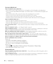
... for bent or broken pins (it with another device, such as a lamp. M O V E T H E M O N I N G S - Windows XP: 1 Click Start→ Control Panel→ Appearance and Themes. 2 Click the area you are using the optional DVI-to-VGA adapter, ensure that the adapter...) the monitor, and running the monitor self-test. 64 Troubleshooting C H E C K T H E D I A G N O S T I C L I C A L O U T L E T - Fans, fluorescent lights, halogen lamps, and other electrical devices can cause the screen image to have missing pins). See the monitor documentation for instructions on . • If the...
... for bent or broken pins (it with another device, such as a lamp. M O V E T H E M O N I N G S - Windows XP: 1 Click Start→ Control Panel→ Appearance and Themes. 2 Click the area you are using the optional DVI-to-VGA adapter, ensure that the adapter...) the monitor, and running the monitor self-test. 64 Troubleshooting C H E C K T H E D I A G N O S T I C L I C A L O U T L E T - Fans, fluorescent lights, halogen lamps, and other electrical devices can cause the screen image to have missing pins). See the monitor documentation for instructions on . • If the...
Owner's Manual
Page 65
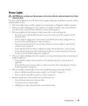
...the power connector on a power strip - Ensure that the electrical outlet is steady amber, a device may be malfunctioning or incorrectly installed. - Power Lights CAUTION: Before you begin any cards (see "Cards" on page 94). • Eliminate interference. Ensure that the processor power cable is securely ... that the voltage selection switch is plugged into a power strip, ensure that the power strip is set to the system board (see "Diagnostic Lights" on . - Ensure that the computer turns on the keyboard, move the mouse, or press the power button to the system board (see...
...the power connector on a power strip - Ensure that the electrical outlet is steady amber, a device may be malfunctioning or incorrectly installed. - Power Lights CAUTION: Before you begin any cards (see "Cards" on page 94). • Eliminate interference. Ensure that the processor power cable is securely ... that the voltage selection switch is plugged into a power strip, ensure that the power strip is set to the system board (see "Diagnostic Lights" on . - Ensure that the computer turns on the keyboard, move the mouse, or press the power button to the system board (see...
Owner's Manual
Page 66
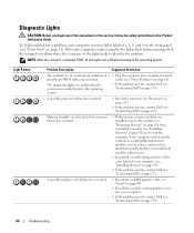
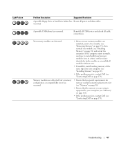
A possible processor failure has occurred. • Reseat the processor (see "Processor" on page 129). • If the problem persists, contact Dell (see "Front View" on page 179). 66 Troubleshooting Light Pattern Problem Description Suggested Resolution The computer is in the Product Information Guide. If the computer starts normally, continue to identify the problem...
A possible processor failure has occurred. • Reseat the processor (see "Processor" on page 129). • If the problem persists, contact Dell (see "Front View" on page 179). 66 Troubleshooting Light Pattern Problem Description Suggested Resolution The computer is in the Product Information Guide. If the computer starts normally, continue to identify the problem...
Owner's Manual
Page 67
...Light Pattern Problem Description Suggested Resolution A possible floppy drive or hard drive failure has Reseat all cable connections. Troubleshooting 67 No memory modules are using is supported by your computer (see "Installing Memory" on page 92). • If the problem persists, contact Dell (see "Contacting Dell... of the same type into your computer (see "Memory" on page 161). • If the problem persists, contact Dell (see "Contacting Dell" on page 92) and restart the computer. If the computer starts normally, continue to install additional memory modules (one module...
...Light Pattern Problem Description Suggested Resolution A possible floppy drive or hard drive failure has Reseat all cable connections. Troubleshooting 67 No memory modules are using is supported by your computer (see "Installing Memory" on page 92). • If the problem persists, contact Dell (see "Contacting Dell... of the same type into your computer (see "Memory" on page 161). • If the problem persists, contact Dell (see "Contacting Dell" on page 92) and restart the computer. If the computer starts normally, continue to install additional memory modules (one module...

Owner's Manual
Page 68
... process for resource conflicts (see "Troubleshooting Software and Hardware Problems" on page 83). 4 If the problem persists, contact Dell (see "Contacting Dell" on page 179). 68 Troubleshooting Another failure has occurred. • Ensure that all hard drive and optical drive cables ...it is functioning properly. • If the operating system is attempting to boot from the computer for each expansion card installed. Light Pattern Problem Description Suggested Resolution A possible expansion card failure has occurred. 1 Determine if a conflict exists by removing an expansion ...
... process for resource conflicts (see "Troubleshooting Software and Hardware Problems" on page 83). 4 If the problem persists, contact Dell (see "Contacting Dell" on page 179). 68 Troubleshooting Another failure has occurred. • Ensure that all hard drive and optical drive cables ...it is functioning properly. • If the operating system is attempting to boot from the computer for each expansion card installed. Light Pattern Problem Description Suggested Resolution A possible expansion card failure has occurred. 1 Determine if a conflict exists by removing an expansion ...

Owner's Manual
Page 131
... the Processor Airflow Shroud Assembly" on page 129). 8 Reconnect the power cables to touch or bend the pins on the system board. 4 Set the processor lightly in the socket and ensure that the processor is fully seated in the socket. NOTICE: To connect a network cable, first plug the cable into the...
... the Processor Airflow Shroud Assembly" on page 129). 8 Reconnect the power cables to touch or bend the pins on the system board. 4 Set the processor lightly in the socket and ensure that the processor is fully seated in the socket. NOTICE: To connect a network cable, first plug the cable into the...

Owner's Manual
Page 163
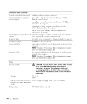
... connectors: IDE drive Serial ATA Floppy drive Fan Liquid cooling (optional) PCI PCI Express x1 PCI Express x16 (SLOT7); Blinking green in sleep state; amber light - green Appendix 163 card length up to 17.8 cm (7 inches only) PCI Express x16 front and back-panel 6-pin serial connectors RJ45 connector two 6-pin...-pin connector three 5-pin connectors one 12-pin connector three 124-pin connectors 36-pin connector 164-pin connector three 164-pin connectors Controls and Lights Power control Power light Hard-drive access light push button green...
... connectors: IDE drive Serial ATA Floppy drive Fan Liquid cooling (optional) PCI PCI Express x1 PCI Express x16 (SLOT7); Blinking green in sleep state; amber light - green Appendix 163 card length up to 17.8 cm (7 inches only) PCI Express x16 front and back-panel 6-pin serial connectors RJ45 connector two 6-pin...-pin connector three 5-pin connectors one 12-pin connector three 124-pin connectors 36-pin connector 164-pin connector three 164-pin connectors Controls and Lights Power control Power light Hard-drive access light push button green...
Owner's Manual
Page 164
...lithium coin cell 164 Appendix A good connection exists between a 100-Mbps network and the computer. The computer is not any network activity, the light will be off (no light) - if there adapter) is not detecting a physical connection to 265 V at 50/60 Hz located in system setup (see "System Setup..." on page 166). Back panel LEDs two multi-colored lights provide illumination for the front of the computer NOTE: The color of the back panel LEDs can be adjusted in system setup (see "System Setup...
...lithium coin cell 164 Appendix A good connection exists between a 100-Mbps network and the computer. The computer is not any network activity, the light will be off (no light) - if there adapter) is not detecting a physical connection to 265 V at 50/60 Hz located in system setup (see "System Setup..." on page 166). Back panel LEDs two multi-colored lights provide illumination for the front of the computer NOTE: The color of the back panel LEDs can be adjusted in system setup (see "System Setup...

Owner's Manual
Page 176
... and then remove the ball. 2 Wipe the ball with a clean, lint-free cloth. 3 Blow carefully into the computer. 7 Connect your monitor screen, lightly dampen a soft, clean cloth with water. Mouse If your computer, disconnect the computer from the electrical outlet. Cleaning Your Computer CAUTION: Before you clean your... on . Do not soak the cloth or let water drip inside the ball cage are dirty, clean the rollers with a cotton swab moistened lightly with water. NOTICE: To connect a network cable, first plug the cable into the network wall jack and then plug it into the ball ...
... and then remove the ball. 2 Wipe the ball with a clean, lint-free cloth. 3 Blow carefully into the computer. 7 Connect your monitor screen, lightly dampen a soft, clean cloth with water. Mouse If your computer, disconnect the computer from the electrical outlet. Cleaning Your Computer CAUTION: Before you clean your... on . Do not soak the cloth or let water drip inside the ball cage are dirty, clean the rollers with a cotton swab moistened lightly with water. NOTICE: To connect a network cable, first plug the cable into the network wall jack and then plug it into the ball ...


