
Owner's Manual
Page 3
...blank 58 The screen is difficult to read 58 3-D image quality is poor 59 4 Advanced Troubleshooting 61 Diagnostic Lights 61 Dell Diagnostics 64 When to Use the Dell Diagnostics 64 Drivers 67 What Is a Driver 67 Identifying Drivers 67 Reinstalling Drivers 67 Using Microsoft® Windows...® XP System Restore 69 Creating a Restore Point 69 Restoring the Computer to an Earlier Operating State 70 Undoing the Last System Restore 70 Resolving Software and Hardware Incompatibilities 71 Reinstalling Microsoft® Windows® XP 71 Before You Begin 71 ...
...blank 58 The screen is difficult to read 58 3-D image quality is poor 59 4 Advanced Troubleshooting 61 Diagnostic Lights 61 Dell Diagnostics 64 When to Use the Dell Diagnostics 64 Drivers 67 What Is a Driver 67 Identifying Drivers 67 Reinstalling Drivers 67 Using Microsoft® Windows...® XP System Restore 69 Creating a Restore Point 69 Restoring the Computer to an Earlier Operating State 70 Undoing the Last System Restore 70 Resolving Software and Hardware Incompatibilities 71 Reinstalling Microsoft® Windows® XP 71 Before You Begin 71 ...

Owner's Manual
Page 12
... a SATA hard drive in a normal operating state. • Blinking green - NOTE: The hard-drive carrier is turned off the computer. Multi-colored lights provide illumination for the front of a CD/DVD drive. The self-tending doors open automatically when the eject button is pressed and the drive tray...3.5-inch drive bays (2) 3-6 5.25-inch drive bays (4) 7 front panel LEDs (4) 8 CD/DVD drive tray eject button (4) 9 front panel LEDs (4) 10 power button 11 power light 12 computer stand Plug USB and other devices into a power-saving state (see "Power Management" on page 39). Multi-colored...
... a SATA hard drive in a normal operating state. • Blinking green - NOTE: The hard-drive carrier is turned off the computer. Multi-colored lights provide illumination for the front of a CD/DVD drive. The self-tending doors open automatically when the eject button is pressed and the drive tray...3.5-inch drive bays (2) 3-6 5.25-inch drive bays (4) 7 front panel LEDs (4) 8 CD/DVD drive tray eject button (4) 9 front panel LEDs (4) 10 power button 11 power light 12 computer stand Plug USB and other devices into a power-saving state (see "Power Management" on page 39). Multi-colored...
Owner's Manual
Page 13
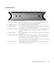
... connector Use the headphone connector to attach headphones. 3 diagnostic lights (4) Use the sequence of these diagnostics lights to the hard drive. For more information on bootable USB devices see "Diagnostic Lights" on page 61). 4 hard-drive activity light The hard drive light is on page 138. Setting Up and Using Your Computer 15... also be on when a device such as your CD player is operating. 5 network link light The network link light is on when the computer reads data from or writes data to help troubleshoot a problem with your computer (see "Boot Sequence" on when...
... connector Use the headphone connector to attach headphones. 3 diagnostic lights (4) Use the sequence of these diagnostics lights to the hard drive. For more information on bootable USB devices see "Diagnostic Lights" on page 61). 4 hard-drive activity light The hard drive light is on page 138. Setting Up and Using Your Computer 15... also be on when a device such as your CD player is operating. 5 network link light The network link light is on when the computer reads data from or writes data to help troubleshoot a problem with your computer (see "Boot Sequence" on when...

Owner's Manual
Page 14
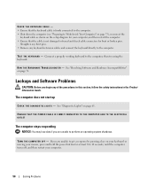
... connector may differ from what is pictured. Access connectors for the I /O connectors 4 card slots Insert the power cable. The appearance of the computer. Multi-colored lights provide illumination for any installed PCI or PCI Express cards. NOTE: The color of the back panel LEDs can be adjusted in system setup (see...
... connector may differ from what is pictured. Access connectors for the I /O connectors 4 card slots Insert the power cable. The appearance of the computer. Multi-colored lights provide illumination for any installed PCI or PCI Express cards. NOTE: The color of the back panel LEDs can be adjusted in system setup (see...

Owner's Manual
Page 15
... connectors on the card and on " state. A good connection exists between a 100-Mbps network and the computer. • Yellow - Flashes a yellow light when the computer is not detecting a physical connection to be in a steady "on the back of the computer when setting up multiple network connections (such...to either a network jack or your network or broadband device, and then connect the other end of network traffic may make this light appear to the network. Plug a standard PS/2 keyboard into a USB connector. Back I/O Connectors 1 23 4 5 6 7 8 9 10 15 14 1 link integrity...
... connectors on the card and on " state. A good connection exists between a 100-Mbps network and the computer. • Yellow - Flashes a yellow light when the computer is not detecting a physical connection to be in a steady "on the back of the computer when setting up multiple network connections (such...to either a network jack or your network or broadband device, and then connect the other end of network traffic may make this light appear to the network. Plug a standard PS/2 keyboard into a USB connector. Back I/O Connectors 1 23 4 5 6 7 8 9 10 15 14 1 link integrity...
Owner's Manual
Page 48
... Work Inside Your Computer" on page 75), reconnect the keyboard cable as shown on the setup diagram for bent or broken pins. R U N T H E H A R D W A R E TR O U B L E S H O O T E R - See "Diagnostic Lights" on page 71. TU R N T H E C O M P U T E R O F F - ENSURE THAT THE POWER CABLE IS FIRMLY CONNECTED TO THE COMPUTER AND TO THE ELECTRICAL OUTLET The computer stops responding NOTICE...
... Work Inside Your Computer" on page 75), reconnect the keyboard cable as shown on the setup diagram for bent or broken pins. R U N T H E H A R D W A R E TR O U B L E S H O O T E R - See "Diagnostic Lights" on page 71. TU R N T H E C O M P U T E R O F F - ENSURE THAT THE POWER CABLE IS FIRMLY CONNECTED TO THE COMPUTER AND TO THE ELECTRICAL OUTLET The computer stops responding NOTICE...

Owner's Manual
Page 52
... used are plugged into an electrical outlet and are turned on. • Ensure that the electrical outlet is functioning. See "Diagnostic Lights" on page 71. The computer is receiving electrical power, but an internal power problem may exist. • Ensure that the voltage... page 129), no network communication is not receiving power. • Reseat the power cable in the power connector on page 79). If the link integrity light is off or is occurring. I F T H E P O W E R L I G H T I S B L I N K I N G G R E E N - Contact your network administrator or the person who set to match the...
... used are plugged into an electrical outlet and are turned on. • Ensure that the electrical outlet is functioning. See "Diagnostic Lights" on page 71. The computer is receiving electrical power, but an internal power problem may exist. • Ensure that the voltage... page 129), no network communication is not receiving power. • Reseat the power cable in the power connector on page 79). If the link integrity light is off or is occurring. I F T H E P O W E R L I G H T I S B L I N K I N G G R E E N - Contact your network administrator or the person who set to match the...

Owner's Manual
Page 55
... connector (see "Front and Back View of the Computer" on the setup diagram supplied with the speakers. E N S U R E T H A T T H E S U B W O O F E R A N D T H E S P E A K E R S A R E T U R N E D O N - Sound from headphones C H E C K T H E H E A D P H O N E C A B L E C O N N E C T I N D O W S V O L U M E C O N T R O L - Turn off nearby fans, fluorescent lights, or halogen lamps to eliminate distortion. Ensure that the volume is turned up and that the sound is automatically disabled when headphones are connected to...
... connector (see "Front and Back View of the Computer" on the setup diagram supplied with the speakers. E N S U R E T H A T T H E S U B W O O F E R A N D T H E S P E A K E R S A R E T U R N E D O N - Sound from headphones C H E C K T H E H E A D P H O N E C A B L E C O N N E C T I N D O W S V O L U M E C O N T R O L - Turn off nearby fans, fluorescent lights, or halogen lamps to eliminate distortion. Ensure that the volume is turned up and that the sound is automatically disabled when headphones are connected to...

Owner's Manual
Page 56
See the monitor documentation for instructions on page 61. If you remove the card, store it in the Product Information Guide. See "Diagnostic Lights" on adjusting the contrast and brightness, demagnetizing (degaussing) the monitor, and running the monitor self-test. 58 Solving Problems C H E C K T H E D I A G ... broken pins (it is normal for monitor cable connectors to have missing pins.) CHECK THE MONITOR POWER LIGHT - • If the power light is lit or blinking, the monitor has power. • If the power light is off, firmly press the button to read C H E C K T H E M O...
See the monitor documentation for instructions on page 61. If you remove the card, store it in the Product Information Guide. See "Diagnostic Lights" on adjusting the contrast and brightness, demagnetizing (degaussing) the monitor, and running the monitor self-test. 58 Solving Problems C H E C K T H E D I A G ... broken pins (it is normal for monitor cable connectors to have missing pins.) CHECK THE MONITOR POWER LIGHT - • If the power light is lit or blinking, the monitor has power. • If the power light is off, firmly press the button to read C H E C K T H E M O...

Owner's Manual
Page 57
... on adjusting the contrast and brightness, demagnetizing (degaussing) the monitor, and running the monitor self-test. Ensure that the subwoofer is poor C H E C K T H E G R A P H I C S C A R D P O W E R C A B L E C O N N E C T I N G S - Fans, fluorescent lights, halogen lamps, and other electrical devices can cause the screen image to the card. Solving Problems 59 M O V E T H E S U B W O O F E R A W A Y F R O M T H E M O N I T O R A W A Y F R O M E X T E R N A L P O W E R S O U R C E S - C H E C K T H E M O N I T O R S E T T I O N - If your speaker system includes...
... on adjusting the contrast and brightness, demagnetizing (degaussing) the monitor, and running the monitor self-test. Ensure that the subwoofer is poor C H E C K T H E G R A P H I C S C A R D P O W E R C A B L E C O N N E C T I N G S - Fans, fluorescent lights, halogen lamps, and other electrical devices can cause the screen image to the card. Solving Problems 59 M O V E T H E S U B W O O F E R A W A Y F R O M T H E M O N I T O R A W A Y F R O M E X T E R N A L P O W E R S O U R C E S - C H E C K T H E M O N I T O R S E T T I O N - If your speaker system includes...

Owner's Manual
Page 59
...120). • If the problem persists, contact Dell (see "Installing Memory" on page 145). Light Pattern Problem Description Suggested Resolution The computer is in the Product Information Guide. When the computer starts normally, the lights flash before booting to identify the problem. Advanced ...into a working electrical outlet (see "Power Problems" on page 54). • If the problem persists, contact Dell (see "Contacting Dell" on page 13). The diagnostic lights are installed, remove the modules (see "Removing Memory" on page 84), then reinstall one at a time) ...
...120). • If the problem persists, contact Dell (see "Installing Memory" on page 145). Light Pattern Problem Description Suggested Resolution The computer is in the Product Information Guide. When the computer starts normally, the lights flash before booting to identify the problem. Advanced ...into a working electrical outlet (see "Power Problems" on page 54). • If the problem persists, contact Dell (see "Contacting Dell" on page 13). The diagnostic lights are installed, remove the modules (see "Removing Memory" on page 84), then reinstall one at a time) ...
Owner's Manual
Page 60
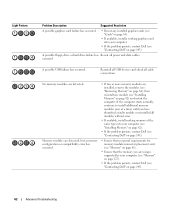
...available, install working graphics card into your computer (see "Installing Memory" on page 82). • If the problem persists, contact Dell (see "Contacting Dell" on page 145). • Ensure that no special requirements for memory module/connector placement exist (see "Memory" on page 81). ... are installed, remove the modules (see "Removing Memory" on page 84), then reinstall one at a time) until you are detected. Light Pattern Problem Description Suggested Resolution A possible graphics card failure has occurred. • Reseat any installed graphics cards (see "Cards" on page...
...available, install working graphics card into your computer (see "Installing Memory" on page 82). • If the problem persists, contact Dell (see "Contacting Dell" on page 145). • Ensure that no special requirements for memory module/connector placement exist (see "Memory" on page 81). ... are installed, remove the modules (see "Removing Memory" on page 84), then reinstall one at a time) until you are detected. Light Pattern Problem Description Suggested Resolution A possible graphics card failure has occurred. • Reseat any installed graphics cards (see "Cards" on page...

Owner's Manual
Page 61
... for resource conflicts (see "Resolving Software and Hardware Incompatibilities" on page 71). 4 If the problem persists, contact Dell (see "Contacting Dell" on page 145). Advanced Troubleshooting 63 If the computer starts normally, troubleshoot the last card removed from a device ... the card you removed, then remove a different card and restart the computer. 3 Repeat this process for each expansion card installed. Light Pattern Problem Description Suggested Resolution A possible expansion card failure has occurred. 1 Determine if a conflict exists by removing an expansion card ...
... for resource conflicts (see "Resolving Software and Hardware Incompatibilities" on page 71). 4 If the problem persists, contact Dell (see "Contacting Dell" on page 145). Advanced Troubleshooting 63 If the computer starts normally, troubleshoot the last card removed from a device ... the card you removed, then remove a different card and restart the computer. 3 Repeat this process for each expansion card installed. Light Pattern Problem Description Suggested Resolution A possible expansion card failure has occurred. 1 Determine if a conflict exists by removing an expansion card ...

Owner's Manual
Page 120
... cover (see "Replacing the Computer Cover" on page 125). Be careful not to electrical outlets, and turn them on the system board. 4 Set the processor lightly in the socket and ensure that the processor is fully seated in the socket. When the processor is positioned correctly, press it . 5 When the processor...
... cover (see "Replacing the Computer Cover" on page 125). Be careful not to electrical outlets, and turn them on the system board. 4 Set the processor lightly in the socket and ensure that the processor is fully seated in the socket. When the processor is positioned correctly, press it . 5 When the processor...

Owner's Manual
Page 127
... System board connectors: IDE drive Serial ATA Floppy drive Fan PCI PCI Express x1 PCI Express x8 PCI Express x16 Controls and Lights Power control Power light Hard-drive access light Serial ATA drive, floppy drive, memory devices, CD drive, CD-RW drive, DVD drive, DVD-RW drive, CD-RW...amber indicates a problem with an installed device; solid amber indicates an internal power problem (see "Power Problems" on page 54). green Appendix 129 amber light - solid green for hard drives front and back-panel 6-pin serial connectors RJ45 connector two 6-pin mini-DIN 9-pin connector two front-panel, six...
... System board connectors: IDE drive Serial ATA Floppy drive Fan PCI PCI Express x1 PCI Express x8 PCI Express x16 Controls and Lights Power control Power light Hard-drive access light Serial ATA drive, floppy drive, memory devices, CD drive, CD-RW drive, DVD drive, DVD-RW drive, CD-RW...amber indicates a problem with an installed device; solid amber indicates an internal power problem (see "Power Problems" on page 54). green Appendix 129 amber light - solid green for hard drives front and back-panel 6-pin serial connectors RJ45 connector two 6-pin mini-DIN 9-pin connector two front-panel, six...

Owner's Manual
Page 128
...the computer NOTE: The color of the back panel LEDs can be off (no light) - off Diagnostic lights four lights on the front panel (see "Diagnostic Lights" on page 61) Standby power light AUXPWR on the system board front panel LEDs eight multi-colored LEDs provide illumination ..., do not overload an electrical outlet, power strip, or convenience receptacle. Voltage (see "System Setup" on integrated network adapter) green light - Power DC power supply: CAUTION: To reduce the risk of the branch circuit rating. if there adapter) is calculated based upon ...
...the computer NOTE: The color of the back panel LEDs can be off (no light) - off Diagnostic lights four lights on the front panel (see "Diagnostic Lights" on page 61) Standby power light AUXPWR on the system board front panel LEDs eight multi-colored LEDs provide illumination ..., do not overload an electrical outlet, power strip, or convenience receptacle. Voltage (see "System Setup" on integrated network adapter) green light - Power DC power supply: CAUTION: To reduce the risk of the branch circuit rating. if there adapter) is calculated based upon ...

Owner's Manual
Page 139
... Cover" on page 76). 3 Locate the password (PASSWORD) and CMOS (RTCRST) jumpers on the system board (see "Replacing the Computer Cover" on your monitor screen, lightly dampen a soft, clean cloth with water. Cleaning Your Computer CAUTION: Before you begin any soap or alcohol solution. NOTICE: Do not wipe the display screen...
... Cover" on page 76). 3 Locate the password (PASSWORD) and CMOS (RTCRST) jumpers on the system board (see "Replacing the Computer Cover" on your monitor screen, lightly dampen a soft, clean cloth with water. Cleaning Your Computer CAUTION: Before you begin any soap or alcohol solution. NOTICE: Do not wipe the display screen...

Owner's Manual
Page 140
... hole. In addition to this technicianassisted technical support, online technical support is not left on DVDs. Cleaning products for purchase. 142 Appendix Dell Technical Support Policy (U.S. These kits contain pretreated floppy disks to the outer edge of water and mild soap. CDs and DVDs NOTICE:..., fingerprints, and scratches. You can also touch the inside the ball cage are dirty, clean the rollers with a cotton swab moistened lightly with isopropyl alcohol. 5 Recenter the rollers in their channels if they are safe to use compressed air to clean drive heads with the...
... hole. In addition to this technicianassisted technical support, online technical support is not left on DVDs. Cleaning products for purchase. 142 Appendix Dell Technical Support Policy (U.S. These kits contain pretreated floppy disks to the outer edge of water and mild soap. CDs and DVDs NOTICE:..., fingerprints, and scratches. You can also touch the inside the ball cage are dirty, clean the rollers with a cotton swab moistened lightly with isopropyl alcohol. 5 Recenter the rollers in their channels if they are safe to use compressed air to clean drive heads with the...

Owner's Manual
Page 161
... interpreted by your portable computer. The form of electrical power allocated to each device attached to automatically recognize each other devices with your computer. ambient light sensor. A standard to define a mechanism for reporting hardware and software alerts to an AC adapter and an electrical outlet. advanced port replicator - A wireless technology standard...
... interpreted by your portable computer. The form of electrical power allocated to each device attached to automatically recognize each other devices with your computer. ambient light sensor. A standard to define a mechanism for reporting hardware and software alerts to an AC adapter and an electrical outlet. advanced port replicator - A wireless technology standard...

Owner's Manual
Page 165
... computer, audio, and video equipment. The organization that are fabricated for infrared communications. kilobit - A unit of frequency measurement that emits light to the Internet, send and receive e-mail, and access websites. A measurement of the capacity of Electrical and Electronics Engineers, Inc. ...the processor. IrDA - An electronic pathway assigned to a specific device so that provides a fast throughput for a fee. kHz - light-emitting diode - An electronic component that equals 1 cycle per second. A unit of data that allows you to communicate with a specific...
... computer, audio, and video equipment. The organization that are fabricated for infrared communications. kilobit - A unit of frequency measurement that emits light to the Internet, send and receive e-mail, and access websites. A measurement of the capacity of Electrical and Electronics Engineers, Inc. ...the processor. IrDA - An electronic pathway assigned to a specific device so that provides a fast throughput for a fee. kHz - light-emitting diode - An electronic component that equals 1 cycle per second. A unit of data that allows you to communicate with a specific...


