Owner's Manual
Page 93
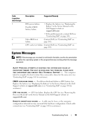
... hardware configuration. Check cable connections (see the documentation for assistance). C M O S C H E C K S U M E R R O R - Replace the battery (see "Replacing the Battery" in the table, see "Contacting Dell" on page 141). Replace the CPU fan (see "Removing the Processor Heatsink" in the Service Manual on page 141 for assistance). ALERT! The computer failed to complete the boot routine...
... hardware configuration. Check cable connections (see the documentation for assistance). C M O S C H E C K S U M E R R O R - Replace the battery (see "Replacing the Battery" in the table, see "Contacting Dell" on page 141). Replace the CPU fan (see "Removing the Processor Heatsink" in the Service Manual on page 141 for assistance). ALERT! The computer failed to complete the boot routine...
Service Manual
Page 17
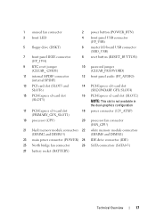
1 unused fan connector 2 power button (POWER_BTN) 3 front LED 4 front panel USB connector (FP_USB) 5 floppy drive (DSKT) 6 master I/O board USB connector (MIO_USB) 7 front panel IEEE connector (FP_1394) 8 reset ...) NOTE: This slot is not available in the dual-graphics configuration 17 PCI-Express x16 card slot (PRIMARY_GFX_SLOT1) 18 power connector (12V_ATXP) 19 processor (CPU) 20 processor fan connector (FAN_CPU) 21 black memory module connectors 22 white memory module connectors (DIMM2 and DIMM 3) (DIMM0 and DIMM1) 23 main power connector (POWER) 24...
1 unused fan connector 2 power button (POWER_BTN) 3 front LED 4 front panel USB connector (FP_USB) 5 floppy drive (DSKT) 6 master I/O board USB connector (MIO_USB) 7 front panel IEEE connector (FP_1394) 8 reset ...) NOTE: This slot is not available in the dual-graphics configuration 17 PCI-Express x16 card slot (PRIMARY_GFX_SLOT1) 18 power connector (12V_ATXP) 19 processor (CPU) 20 processor fan connector (FAN_CPU) 21 black memory module connectors 22 white memory module connectors (DIMM2 and DIMM 3) (DIMM0 and DIMM1) 23 main power connector (POWER) 24...


