
Owner's Manual
Page 7
CD/DVD Drive 108 Removing a CD/DVD Drive 109 Installing a CD/DVD Drive 110 Processor Airflow Shroud 112 Removing the Processor Airflow Shroud 112 Installing the Processor Airflow Shroud 113 Processor 113 Removing the Processor 113 Installing the Processor 117 Front Panel 120 Removing the Front Panel 120 Replacing the Front Panel 120 Drive Door 121 Removing...
CD/DVD Drive 108 Removing a CD/DVD Drive 109 Installing a CD/DVD Drive 110 Processor Airflow Shroud 112 Removing the Processor Airflow Shroud 112 Installing the Processor Airflow Shroud 113 Processor 113 Removing the Processor 113 Installing the Processor 117 Front Panel 120 Removing the Front Panel 120 Replacing the Front Panel 120 Drive Door 121 Removing...

Owner's Manual
Page 12
...operating system and support for your Dell computer. Online discussion with technical support • Reference - DSS provides critical updates for Dell 3.5-inch USB floppy drives, Intel® Pentium® M processors, optical drives, and USB devices. support.dell.com NOTE: Select your computer... information, service call status and support history, service contract, and online discussions with other Dell NOTE: Corporate, government, and education customers customers can also use Windows XP Windows Help and Support Center 1 Click the Start button, then click Help and Support....
...operating system and support for your Dell computer. Online discussion with technical support • Reference - DSS provides critical updates for Dell 3.5-inch USB floppy drives, Intel® Pentium® M processors, optical drives, and USB devices. support.dell.com NOTE: Select your computer... information, service call status and support history, service contract, and online discussions with other Dell NOTE: Corporate, government, and education customers customers can also use Windows XP Windows Help and Support Center 1 Click the Start button, then click Help and Support....
Owner's Manual
Page 37
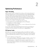
...the Microsoft® Windows® XP Service Pack 1 (SP1) or later operating system because Windows XP is listed twice. Multiple PCI cards installed in a PCI card slot). If Hyper-Threading is enabled, the processor is optimized to Processors. It is recommended that can enhance... overall computer performance by allowing one direction at support.dell.com. Optimizing Performance...
...the Microsoft® Windows® XP Service Pack 1 (SP1) or later operating system because Windows XP is listed twice. Multiple PCI cards installed in a PCI card slot). If Hyper-Threading is enabled, the processor is optimized to Processors. It is recommended that can enhance... overall computer performance by allowing one direction at support.dell.com. Optimizing Performance...
Owner's Manual
Page 49
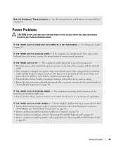
... computer turns on properly. • Ensure that the electrical outlet is working by testing it with another device, such as a lamp. • Ensure that the processor power cable is securely connected to match the AC power at your location (if applicable). I F T H E P O W E R L I G H T I S B L I N K I S S T E A D Y A M B E R - A device might exist. • Ensure that the power strip is...
... computer turns on properly. • Ensure that the electrical outlet is working by testing it with another device, such as a lamp. • Ensure that the processor power cable is securely connected to match the AC power at your location (if applicable). I F T H E P O W E R L I G H T I S B L I N K I S S T E A D Y A M B E R - A device might exist. • Ensure that the power strip is...
Owner's Manual
Page 55
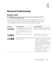
... • If you troubleshoot a problem, your computer (see "Installing Memory" on page 80). • If the problem persists, contact Dell (see "Contacting Dell" on page 142). After the computer starts, all modules without error. • If available, install properly working electrical a possible pre-BIOS ...and restart the computer. Continue until you have two or more memory modules installed, remove the modules, reinstall one module (see "Processor" on page 72). If the computer malfunctions, the color and sequence of the lights identify the problem. If the computer starts ...
... • If you troubleshoot a problem, your computer (see "Installing Memory" on page 80). • If the problem persists, contact Dell (see "Contacting Dell" on page 142). After the computer starts, all modules without error. • If available, install properly working electrical a possible pre-BIOS ...and restart the computer. Continue until you have two or more memory modules installed, remove the modules, reinstall one module (see "Processor" on page 72). If the computer malfunctions, the color and sequence of the lights identify the problem. If the computer starts ...
Owner's Manual
Page 70
...NOTICE: Before touching anything inside the computer. 1 Turn off your computer, ground yourself by touching an unpainted metal surface, such as a processor by its edges, not by its metal mounting bracket. NOTICE: To avoid damaging the computer, perform the following safety guidelines to help ensure... of the computer. Also, before you begin working inside your computer (see "Opening the Computer Cover" on page 76). www.dell.com | support.dell.com Before Working Inside Your Computer Use the following steps before opening the cover. 4 Open the computer cover (see "Turning Off...
...NOTICE: Before touching anything inside the computer. 1 Turn off your computer, ground yourself by touching an unpainted metal surface, such as a processor by its edges, not by its metal mounting bracket. NOTICE: To avoid damaging the computer, perform the following safety guidelines to help ensure... of the computer. Also, before you begin working inside your computer (see "Opening the Computer Cover" on page 76). www.dell.com | support.dell.com Before Working Inside Your Computer Use the following steps before opening the cover. 4 Open the computer cover (see "Turning Off...
Owner's Manual
Page 73
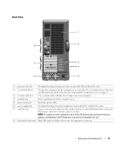
Back View 1 2 8 7 3 4 6 5 1 processor fans (2) For optimal cooling, two processor fans are provided. Do not block the vents. 7 card slots (6) Access connectors for use. 8 back panel connectors Plug USB, audio, and other PCI cards (three ...
Back View 1 2 8 7 3 4 6 5 1 processor fans (2) For optimal cooling, two processor fans are provided. Do not block the vents. 7 card slots (6) Access connectors for use. 8 back panel connectors Plug USB, audio, and other PCI cards (three ...

Owner's Manual
Page 77
Inside View of Your Computer floppy drive CD/DVD drive processor airflow shroud hard drive shroud PCI card shroud and fan processor fan power supply fans (2) system board power supply Removing and Installing Parts 77
Inside View of Your Computer floppy drive CD/DVD drive processor airflow shroud hard drive shroud PCI card shroud and fan processor fan power supply fans (2) system board power supply Removing and Installing Parts 77

Owner's Manual
Page 78
...) PCI card connectors (PCI SLOT 4, PCI SLOT 5, PCI SLOT 6) 78 Removing and Installing Parts www.dell.com | support.dell.com System Board Components password jumper (PASSWORD) main power connector (POWER) memory module connectors (2, 4) memory module connectors (1, 3) processor and heat-sink connector power connector (POWER12V) optical drive connector (IDE) floppy-drive connector (FLOPPY) front...
...) PCI card connectors (PCI SLOT 4, PCI SLOT 5, PCI SLOT 6) 78 Removing and Installing Parts www.dell.com | support.dell.com System Board Components password jumper (PASSWORD) main power connector (POWER) memory module connectors (2, 4) memory module connectors (1, 3) processor and heat-sink connector power connector (POWER12V) optical drive connector (IDE) floppy-drive connector (FLOPPY) front...

Owner's Manual
Page 79
... memory configurations are not installed in matched pairs, the computer will continue to operate, but with a slight reduction in pairs of the module to the processor, before you install modules in the other connectors.
... memory configurations are not installed in matched pairs, the computer will continue to operate, but with a slight reduction in pairs of the module to the processor, before you install modules in the other connectors.

Owner's Manual
Page 81
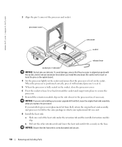
memory connector closest to each end of the module with the crossbar in the connector. Removing and Installing Parts 81 If you insert the module correctly, the securing clips snap into the connector while you apply equal force to processor securing clips (2) connector 4 Align the notch on the bottom of the module. notch memory module cutouts (2) crossbar NOTICE: To avoid damage to the memory module, press the module straight down into the cutouts at each end of the module. 5 Insert the module into the connector until the module snaps into position.
memory connector closest to each end of the module with the crossbar in the connector. Removing and Installing Parts 81 If you insert the module correctly, the securing clips snap into the connector while you apply equal force to processor securing clips (2) connector 4 Align the notch on the bottom of the module. notch memory module cutouts (2) crossbar NOTICE: To avoid damage to the memory module, press the module straight down into the cutouts at each end of the module. 5 Insert the module into the connector until the module snaps into position.

Owner's Manual
Page 112
...You can do not slide the shroud too quickly. www.dell.com | support.dell.com 11 Verify that your computer works correctly by running the Dell Diagnostics (see "Dell Diagnostics" on the computer chassis. Processor Airflow Shroud CAUTION: Before you touch any of your computer...'s electronic components. Removing the Processor Airflow Shroud 1 Follow the procedures in the Product Information ...
...You can do not slide the shroud too quickly. www.dell.com | support.dell.com 11 Verify that your computer works correctly by running the Dell Diagnostics (see "Dell Diagnostics" on the computer chassis. Processor Airflow Shroud CAUTION: Before you touch any of your computer...'s electronic components. Removing the Processor Airflow Shroud 1 Follow the procedures in the Product Information ...

Owner's Manual
Page 113
... Attach both fan power cables to the connectors on the system board. 2 Align the anchor tabs with hardware removal and replacement. Processor NOTICE: Do not perform the following steps unless you begin any of the procedures in this section, follow the safety instructions located... connectors (see "System Board Components" on page 78) on the system board. 3 Disconnect the power cable from the POWER12V connector (see "Dell Technical Support Policy (U.S. Only)" on the system board. 4 Remove the airflow shroud. Removing and Installing Parts 113 Performing these steps incorrectly could ...
... Attach both fan power cables to the connectors on the system board. 2 Align the anchor tabs with hardware removal and replacement. Processor NOTICE: Do not perform the following steps unless you begin any of the procedures in this section, follow the safety instructions located... connectors (see "System Board Components" on page 78) on the system board. 3 Disconnect the power cable from the POWER12V connector (see "Dell Technical Support Policy (U.S. Only)" on the system board. 4 Remove the airflow shroud. Removing and Installing Parts 113 Performing these steps incorrectly could ...

Owner's Manual
Page 115
... the heat sink: NOTICE: After the heat sink has been removed, lay the heat sink down on its side to remove it out of the processor.
... the heat sink: NOTICE: After the heat sink has been removed, lay the heat sink down on its side to remove it out of the processor.
Owner's Manual
Page 116
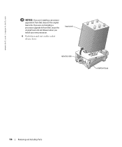
heat sink retention tab retention base 116 Removing and Installing Parts If you install your new processor. 6 Push down and out on the socket release lever. www.dell.com | support.dell.com NOTICE: If you are not installing a processor upgrade kit from Dell, reuse the original heat sink and blower when you are installing a processor upgrade kit from Dell, discard the original heat sink.
heat sink retention tab retention base 116 Removing and Installing Parts If you install your new processor. 6 Push down and out on the socket release lever. www.dell.com | support.dell.com NOTICE: If you are not installing a processor upgrade kit from Dell, reuse the original heat sink and blower when you are installing a processor upgrade kit from Dell, discard the original heat sink.

Owner's Manual
Page 117
...the socket is not fully extended, move it to that position. processor cover processor socket release lever 8 Remove the processor from the socket. Leave the release lever extended in the socket to avoid permanent damage to the processor and the computer when you turn on the computer. 2 If the... release lever on the back of the computer. 1 Unpack the new processor. Removing and Installing Parts 117 Installing the Processor NOTICE: Ground yourself by touching an unpainted ...
...the socket is not fully extended, move it to that position. processor cover processor socket release lever 8 Remove the processor from the socket. Leave the release lever extended in the socket to avoid permanent damage to the processor and the computer when you turn on the computer. 2 If the... release lever on the back of the computer. 1 Unpack the new processor. Removing and Installing Parts 117 Installing the Processor NOTICE: Ground yourself by touching an unpainted ...
Owner's Manual
Page 118
... to seat it. 5 When the processor is aligned properly with minimal pressure to the processor fan, if necessary. If you installed a processor replacement kit from Dell, reuse the original heat sink assembly when you install the processor. NOTICE: Ensure that the processor is fully seated in the socket. www.dell.com | support.dell.com 3 Align the pin-1 corner...
... to seat it. 5 When the processor is aligned properly with minimal pressure to the processor fan, if necessary. If you installed a processor replacement kit from Dell, reuse the original heat sink assembly when you install the processor. NOTICE: Ensure that the processor is fully seated in the socket. www.dell.com | support.dell.com 3 Align the pin-1 corner...

Owner's Manual
Page 127
... levels BIOS chip (NVRAM) NIC System clock Video Type Intel® Pentium® 4 Extreme Edition with HT Technology or dualcore processing NOTE: Not all Pentium 4 processors support Hyper-Threading technology or dual-core processing. 1 MB or 2 MB 533- F0000h Nvidia nForce4 SLI X16 MCP five 24 4 Mb integrated network interface capable... DDR2 unbuffered SDRAM four 256 MB, 512 MB, 1 GB, or 2 GB non-ECC 512 MB 2 GB or 8 GB NOTE: See "Addressing Memory Configurations" on your processor) PCI Express Appendix 127
... levels BIOS chip (NVRAM) NIC System clock Video Type Intel® Pentium® 4 Extreme Edition with HT Technology or dualcore processing NOTE: Not all Pentium 4 processors support Hyper-Threading technology or dual-core processing. 1 MB or 2 MB 533- F0000h Nvidia nForce4 SLI X16 MCP five 24 4 Mb integrated network interface capable... DDR2 unbuffered SDRAM four 256 MB, 512 MB, 1 GB, or 2 GB non-ECC 512 MB 2 GB or 8 GB NOTE: See "Addressing Memory Configurations" on your processor) PCI Express Appendix 127

Owner's Manual
Page 132
... Info Memory Info PCI Info Date/Time Lists system information such as listed. www.dell.com | support.dell.com Options List - Press to highlight an option. Identifies whether the computer's processor supports Hyper-Threading and lists the processor bus speed, processor ID, clock speed, and L2 cache. This field appears on your computer and installed...
... Info Memory Info PCI Info Date/Time Lists system information such as listed. www.dell.com | support.dell.com Options List - Press to highlight an option. Identifies whether the computer's processor supports Hyper-Threading and lists the processor bus speed, processor ID, clock speed, and L2 cache. This field appears on your computer and installed...

Owner's Manual
Page 133
... to an operating system on the computer. Enables or disables the onboard audio controller. (Default On) Enables or disables the internal USB controller. If your processor supports Hyper-Threading, this system. Boot Sequence Drives Diskette Drive SATA Drives 0 through 3 PATA Drives 0 through 1 Smart Reporting Onboard Devices Integrated NIC Audio Controller USB...
... to an operating system on the computer. Enables or disables the onboard audio controller. (Default On) Enables or disables the internal USB controller. If your processor supports Hyper-Threading, this system. Boot Sequence Drives Diskette Drive SATA Drives 0 through 3 PATA Drives 0 through 1 Smart Reporting Onboard Devices Integrated NIC Audio Controller USB...


