Owners Manual
Page 5
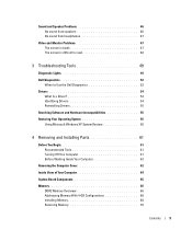
...47 The screen is blank 47 The screen is difficult to read 48 3 Troubleshooting Tools 49 Diagnostic Lights 49 Dell Diagnostics 52 When to Use the Dell Diagnostics 52 Drivers 54 What Is a Driver 54 Identifying Drivers 54 Reinstalling Drivers 55 Resolving Software and Hardware ...Incompatibilities 56 Restoring Your Operating System 56 Using Microsoft Windows XP System Restore 56 4 Removing and Installing Parts 61 Before You Begin ...
...47 The screen is blank 47 The screen is difficult to read 48 3 Troubleshooting Tools 49 Diagnostic Lights 49 Dell Diagnostics 52 When to Use the Dell Diagnostics 52 Drivers 54 What Is a Driver 54 Identifying Drivers 54 Reinstalling Drivers 55 Resolving Software and Hardware ...Incompatibilities 56 Restoring Your Operating System 56 Using Microsoft Windows XP System Restore 56 4 Removing and Installing Parts 61 Before You Begin ...
Owners Manual
Page 33
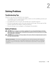
.... If you have to the manufacturer's instructions. Solving Problems Troubleshooting Tips Follow these tips when you troubleshoot your computer: • If you added or removed a part before the problem started, review the installation procedures and ensure that the part is correctly installed. • If a peripheral device does not work properly, contact...
.... If you have to the manufacturer's instructions. Solving Problems Troubleshooting Tips Follow these tips when you troubleshoot your computer: • If you added or removed a part before the problem started, review the installation procedures and ensure that the part is correctly installed. • If a peripheral device does not work properly, contact...

Owners Manual
Page 53
When contacting Dell support, have your part. Describes the test and any problem encountered during a test, a message ... requires no interaction on your computer or all the components installed on your Service Tag ready. The Dell Diagnostics obtains configuration information for all devices from system setup, memory, and various internal tests, and ...of common symptoms and allows you to customize the test, if applicable, by changing the test settings. Dell Diagnostics Main Menu The following tabs provide additional information for tests run from the Custom Test or Symptom ...
When contacting Dell support, have your part. Describes the test and any problem encountered during a test, a message ... requires no interaction on your computer or all the components installed on your Service Tag ready. The Dell Diagnostics obtains configuration information for all devices from system setup, memory, and various internal tests, and ...of common symptoms and allows you to customize the test, if applicable, by changing the test settings. Dell Diagnostics Main Menu The following tabs provide additional information for tests run from the Custom Test or Symptom ...

Owners Manual
Page 61
...you shut down the operating system: a Save and close any open programs, click Start, and then click Turn Off Computer. Removing and Installing Parts 61 The computer turns off . If your computer and attached devices did not automatically turn off when you turn off . b In the ...Turn off computer window, click Turn off your Dell™ Product Information Guide. • A component can be replaced or-if purchased separately-installed by performing the removal procedure in reverse order. ...
...you shut down the operating system: a Save and close any open programs, click Start, and then click Turn Off Computer. Removing and Installing Parts 61 The computer turns off . If your computer and attached devices did not automatically turn off when you turn off . b In the ...Turn off computer window, click Turn off your Dell™ Product Information Guide. • A component can be replaced or-if purchased separately-installed by performing the removal procedure in reverse order. ...

Owners Manual
Page 62
...that could harm internal components. Before you work, periodically touch an unpainted metal surface to servicing that is not authorized by Dell is not covered by its metal mounting bracket. Damage due to dissipate any telephone or telecommunication lines from the electrical outlet before...Disconnect your computer and all attached devices from potential damage and to help protect your computer from the computer. 62 Removing and Installing Parts As you begin working inside your computer (see "Removing the Computer Cover" on page 61). CAUTION: Before you pull connectors ...
...that could harm internal components. Before you work, periodically touch an unpainted metal surface to servicing that is not authorized by Dell is not covered by its metal mounting bracket. Damage due to dissipate any telephone or telecommunication lines from the electrical outlet before...Disconnect your computer and all attached devices from potential damage and to help protect your computer from the computer. 62 Removing and Installing Parts As you begin working inside your computer (see "Removing the Computer Cover" on page 61). CAUTION: Before you pull connectors ...
Owners Manual
Page 63
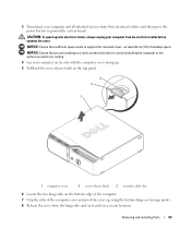
... computer cover facing up , using the bottom hinges as leverage points. 8 Release the cover from the electrical outlet before opening the cover. Removing and Installing Parts 63 3 Disconnect your computer and all attached devices from their electrical outlets, and then press the power button to avoid scratching the computer or the...
... computer cover facing up , using the bottom hinges as leverage points. 8 Release the cover from the electrical outlet before opening the cover. Removing and Installing Parts 63 3 Disconnect your computer and all attached devices from their electrical outlets, and then press the power button to avoid scratching the computer or the...

Owners Manual
Page 64
CAUTION: To guard against electrical shock, always unplug your computer from the electrical outlet before opening the cover. 2 1 3 4 7 6 5 1 drive release latch 4 hard drive 7 front-panel door 2 CD/DVD drive 5 heat sink assembly 3 power supply and fan 6 power button 64 Removing and Installing Parts Inside View of Your Computer CAUTION: Before you begin any of the procedures in this section, follow the safety instructions located in the Product Information Guide.
CAUTION: To guard against electrical shock, always unplug your computer from the electrical outlet before opening the cover. 2 1 3 4 7 6 5 1 drive release latch 4 hard drive 7 front-panel door 2 CD/DVD drive 5 heat sink assembly 3 power supply and fan 6 power button 64 Removing and Installing Parts Inside View of Your Computer CAUTION: Before you begin any of the procedures in this section, follow the safety instructions located in the Product Information Guide.
Owners Manual
Page 65
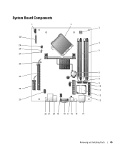
System Board Components 1 2 3 30 4 29 28 5 27 26 6 25 7 8 9 10 24 11 12 23 13 22 21 20 19 18 17 16 15 14 Removing and Installing Parts 65
System Board Components 1 2 3 30 4 29 28 5 27 26 6 25 7 8 9 10 24 11 12 23 13 22 21 20 19 18 17 16 15 14 Removing and Installing Parts 65
Owners Manual
Page 66
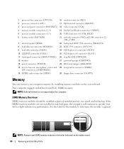
... jumper (CLRPSWD) 13 power connector (POWER) 28 RTC reset jumper (CLRCMOS) 14 line-in the order indicated on the system board. 66 Removing and Installing Parts If the DDR2 memory modules are not installed in matched pairs, the computer will continue to determine the module's capacity. DDR2 Memory Overview DDR2 memory...
... jumper (CLRPSWD) 13 power connector (POWER) 28 RTC reset jumper (CLRCMOS) 14 line-in the order indicated on the system board. 66 Removing and Installing Parts If the DDR2 memory modules are not installed in matched pairs, the computer will continue to determine the module's capacity. DDR2 Memory Overview DDR2 memory...

Owners Manual
Page 67
... memory modules from the computer during a memory upgrade, keep them separate from Dell. If possible, do not pair an original memory module with a new memory module. Otherwise, your computer warranty. Removing and Installing Parts 67 NOTE: Memory purchased from Dell is covered under your computer may have, even if you purchased the new...
... memory modules from the computer during a memory upgrade, keep them separate from Dell. If possible, do not pair an original memory module with a new memory module. Otherwise, your computer warranty. Removing and Installing Parts 67 NOTE: Memory purchased from Dell is covered under your computer may have, even if you purchased the new...
Owners Manual
Page 68
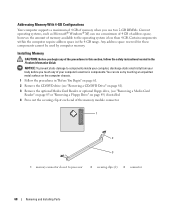
... of the memory module connector. 1 2 3 1 memory connector closest to processor 2 securing clips (2) 3 connector 68 Removing and Installing Parts You can use two 2-GB DIMMs. Current operating systems, such as Microsoft® Windows® XP, can do so by computer memory. Installing Memory CAUTION: Before you begin any of your body before you...
... of the memory module connector. 1 2 3 1 memory connector closest to processor 2 securing clips (2) 3 connector 68 Removing and Installing Parts You can use two 2-GB DIMMs. Current operating systems, such as Microsoft® Windows® XP, can do so by computer memory. Installing Memory CAUTION: Before you begin any of your body before you...

Owners Manual
Page 69
Removing and Installing Parts 69 5 Align the notch on the bottom of the module with the crossbar in the connector. 1 3 4 2 1 notch 3 memory module 2 crossbar 4 cutouts (2) NOTICE: To avoid damage ...
Removing and Installing Parts 69 5 Align the notch on the bottom of the module with the crossbar in the connector. 1 3 4 2 1 notch 3 memory module 2 crossbar 4 cutouts (2) NOTICE: To avoid damage ...

Owners Manual
Page 70
... You can do so by touching an unpainted metal surface on the computer chassis. 1 Follow the procedures in the Product Information Guide. Your Dell™ computer provides the following slots for PCI Express cards: • One PCI Express x16 card slot • One PCI Express x1 ... 2 3 4 1 PCI Express x16 card 3 PCI Express x1 card slot 2 PCI Express x1 card 4 PCI Express x16 card slot 70 Removing and Installing Parts Cards CAUTION: Before you begin any of the procedures in this section, follow the safety instructions located in "Before You Begin" on the computer chassis...
... You can do so by touching an unpainted metal surface on the computer chassis. 1 Follow the procedures in the Product Information Guide. Your Dell™ computer provides the following slots for PCI Express cards: • One PCI Express x16 card slot • One PCI Express x1 ... 2 3 4 1 PCI Express x16 card 3 PCI Express x1 card slot 2 PCI Express x1 card 4 PCI Express x16 card slot 70 Removing and Installing Parts Cards CAUTION: Before you begin any of the procedures in this section, follow the safety instructions located in "Before You Begin" on the computer chassis...

Owners Manual
Page 71
Removing and Installing Parts 71 If you are removing but not replacing a card, see "Removing a PCI Express Card" on the card retention door from the operating system. If necessary, ...
Removing and Installing Parts 71 If you are removing but not replacing a card, see "Removing a PCI Express Card" on the card retention door from the operating system. If necessary, ...

Owners Manual
Page 72
... in the slot. 1 2 4 3 1 card not fully seated 3 bracket caught outside of the card or filler bracket fits around the alignment guide. 72 Removing and Installing Parts
... in the slot. 1 2 4 3 1 card not fully seated 3 bracket caught outside of the card or filler bracket fits around the alignment guide. 72 Removing and Installing Parts
Owners Manual
Page 73
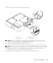
... cables that came with the card for the card as described in the card documentation. Cables routed over or behind the cards. Removing and Installing Parts 73 See the documentation that should be attached to the card. 10 Close the card retention door by snapping it into place. 1 2 3 4 1 retention arm 3 edge...
... cables that came with the card for the card as described in the card documentation. Cables routed over or behind the cards. Removing and Installing Parts 73 See the documentation that should be attached to the card. 10 Close the card retention door by snapping it into place. 1 2 3 4 1 retention arm 3 edge...

Owners Manual
Page 74
... "SATA1" on page 61. 2 If necessary, disconnect any cables connected to electrical outlets, and then turn them on the system board. 74 Removing and Installing Parts Removing a PCI Express Card 1 Follow the procedures in the empty card-slot opening.
... "SATA1" on page 61. 2 If necessary, disconnect any cables connected to electrical outlets, and then turn them on the system board. 74 Removing and Installing Parts Removing a PCI Express Card 1 Follow the procedures in the empty card-slot opening.

Owners Manual
Page 75
... or a missing pin on one connector matches a tab or a filled-in hole on the system board. 1 power input connector 1 2 2 power cable connector Removing and Installing Parts 75 Reversing the cable prevents the drive from pin 1 of the connector. Connecting Drive Cables When you install a drive, you connect a SATA interface cable, do...
... or a missing pin on one connector matches a tab or a filled-in hole on the system board. 1 power input connector 1 2 2 power cable connector Removing and Installing Parts 75 Reversing the cable prevents the drive from pin 1 of the connector. Connecting Drive Cables When you install a drive, you connect a SATA interface cable, do...

Owners Manual
Page 76
... drive and slide the drive up your files before removing the cover. that contains data you begin any of the computer. 76 Removing and Installing Parts NOTICE: To avoid damage to the drive, do not set the drive on a surface, such as a foam pad, that it is , a notch or a missing pin...
... drive and slide the drive up your files before removing the cover. that contains data you begin any of the computer. 76 Removing and Installing Parts NOTICE: To avoid damage to the drive, do not set the drive on a surface, such as a foam pad, that it is , a notch or a missing pin...

Owners Manual
Page 77
1 2 1 tabs (2) 2 hard drive NOTICE: Do not pull the drive out of the computer and disconnect the power and hard-drive cables from the drive. 1 2 1 power cable 2 hard drive cable or serial ATA data cable Removing and Installing Parts 77 Doing so may cause damage to cables and the cable connectors. 3 Lift the drive out of the computer by the drive cables.
1 2 1 tabs (2) 2 hard drive NOTICE: Do not pull the drive out of the computer and disconnect the power and hard-drive cables from the drive. 1 2 1 power cable 2 hard drive cable or serial ATA data cable Removing and Installing Parts 77 Doing so may cause damage to cables and the cable connectors. 3 Lift the drive out of the computer by the drive cables.

