Handling swollen Lithium-ion batteries
Page 1
... (especially with your computer. We recommend contacting Dell product support for options to reassemble a damaged or swollen battery into a notebook PC. ● Swollen batteries should be dangerous. ● Do not attempt to replace a swollen battery under the terms of the applicable warranty or ...service contract, including options for swelling of the battery cells Swollen battery may impact the performance of swelling, do not try to free it by Dell), to malfunction, discontinue the use a battery from the system. or its subsidiaries. Other trademarks may...
... (especially with your computer. We recommend contacting Dell product support for options to reassemble a damaged or swollen battery into a notebook PC. ● Swollen batteries should be dangerous. ● Do not attempt to replace a swollen battery under the terms of the applicable warranty or ...service contract, including options for swelling of the battery cells Swollen battery may impact the performance of swelling, do not try to free it by Dell), to malfunction, discontinue the use a battery from the system. or its subsidiaries. Other trademarks may...

Handling swollen Lithium-ion batteries
Page 2
For more information on how to improve the performance and lifespan of the issue, see Dell Laptop Battery - Lithium-ion batteries can swell for various reasons such as age, number of charge cycles, or exposure to minimize the possibility of occurrence of the laptop battery and to high heat. Frequently Asked Questions. 2
For more information on how to improve the performance and lifespan of the issue, see Dell Laptop Battery - Lithium-ion batteries can swell for various reasons such as age, number of charge cycles, or exposure to minimize the possibility of occurrence of the laptop battery and to high heat. Frequently Asked Questions. 2
Vostro 15 - 3568 Quick Start Guide -Windows 10
Page 2
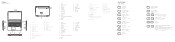
... 3.0 ポート 16. Memory card reader 10. Speaker 12. Network port 19. Battery 21. Battery latch 22. HDMI 連接埠 17. USB 2.0 ポート 8 9 10 11 12 13 14 15. HDMI ポート 17. Camera-status light 3. Security-cable slot 5. USB 3.0 ...;接埠 8 9 10 11. 喇叭 12 示燈 13. 觸控墊 14. 喇叭 15. Power and battery-status light/ hard-drive activity light 13. HDMI 端口 17. VGA ポート 18 19 20 21 22 Shortcut...
... 3.0 ポート 16. Memory card reader 10. Speaker 12. Network port 19. Battery 21. Battery latch 22. HDMI 連接埠 17. USB 2.0 ポート 8 9 10 11 12 13 14 15. HDMI ポート 17. Camera-status light 3. Security-cable slot 5. USB 3.0 ...;接埠 8 9 10 11. 喇叭 12 示燈 13. 觸控墊 14. 喇叭 15. Power and battery-status light/ hard-drive activity light 13. HDMI 端口 17. VGA ポート 18 19 20 21 22 Shortcut...
Vostro 15-3568 Owners Manual
Page 3
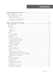
...11 Left view ...12 Palm rest view...13 Right view...13 Battery...14 Removing the battery...14 Installing the battery...14 Optical drive...15 Removing the optical drive ...15 Removing the optical drive bracket...15 Installing the optical drive bracket...16 Installing the optical drive...16 Keyboard...WLAN card...24 Memory modules...24 Removing the memory module...24 Installing the memory module...25 Coin-cell battery...26 Removing the coin cell battery...26 Installing the coin cell battery...26 Contents 3 Windows...8 Turning off your - Contents Chapter 1: Working on your computer 7 Safety ...
...11 Left view ...12 Palm rest view...13 Right view...13 Battery...14 Removing the battery...14 Installing the battery...14 Optical drive...15 Removing the optical drive ...15 Removing the optical drive bracket...15 Installing the optical drive bracket...16 Installing the optical drive...16 Keyboard...WLAN card...24 Memory modules...24 Removing the memory module...24 Installing the memory module...25 Coin-cell battery...26 Removing the coin cell battery...26 Installing the coin cell battery...26 Contents 3 Windows...8 Turning off your - Contents Chapter 1: Working on your computer 7 Safety ...
Vostro 15-3568 Owners Manual
Page 8
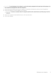
... 1. Click Start. 2. NOTE: Ensure that the computer and all open files and exit all attached devices are turned off your - Remove the main battery. 9. NOTE: Ensure that you shut down . CAUTION: To guard against electrical shock, always unplug your computer. 8 Working on a flat work ,... Cards from the appropriate slots. After working inside your computer NOTE: To avoid damaging the system board, you must remove the main battery before you service the computer. 8. Windows CAUTION: To avoid losing data, save and close all open programs before you turn off ...
... 1. Click Start. 2. NOTE: Ensure that the computer and all open files and exit all attached devices are turned off your - Remove the main battery. 9. NOTE: Ensure that you shut down . CAUTION: To guard against electrical shock, always unplug your computer. 8 Working on a flat work ,... Cards from the appropriate slots. After working inside your computer NOTE: To avoid damaging the system board, you must remove the main battery before you service the computer. 8. Windows CAUTION: To avoid losing data, save and close all open programs before you turn off ...
Vostro 15-3568 Owners Manual
Page 9
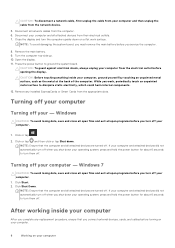
... as a port replicator or media base, and replace any telephone or network cables to the computer, use batteries designed for this particular Dell computer. Working on your computer 9 Do not use only the battery designed for other Dell computers. 1. CAUTION: To avoid damage to your computer. Connect your computer and all attached devices to...
... as a port replicator or media base, and replace any telephone or network cables to the computer, use batteries designed for this particular Dell computer. Working on your computer 9 Do not use only the battery designed for other Dell computers. 1. CAUTION: To avoid damage to your computer. Connect your computer and all attached devices to...
Vostro 15-3568 Owners Manual
Page 10
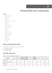
Vostro 15-3562 screw size list Component M2L3 M2L2(Bi M2L2(Bi M2.5L8 g g head07) head05) Optical drive 1 Optical drive bracket 1 Base Cover 8 Hard drive 4 M2L5 5 M2.5L2. 5 (Big head) M3L3 M2L3 M2L2 5 10 Disassembly and reassembly 2 Disassembly and reassembly Topics: • Recommended tools • Screw size list • Chassis view • Battery... Keyboard • Base cover • Hard drive • WLAN card • Memory modules • Coin-cell battery • Power button board • Heat sink • System fan • Speaker • System board •...
Vostro 15-3562 screw size list Component M2L3 M2L2(Bi M2L2(Bi M2.5L8 g g head07) head05) Optical drive 1 Optical drive bracket 1 Base Cover 8 Hard drive 4 M2L5 5 M2.5L2. 5 (Big head) M3L3 M2L3 M2L2 5 10 Disassembly and reassembly 2 Disassembly and reassembly Topics: • Recommended tools • Screw size list • Chassis view • Battery... Keyboard • Base cover • Hard drive • WLAN card • Memory modules • Coin-cell battery • Power button board • Heat sink • System fan • Speaker • System board •...

Vostro 15-3568 Owners Manual
Page 12
USB 3.1 Gen 1 connector 2. Network connector (No LED indicator) 4. Power and battery-status light/ Hard-drive activity light 2. LCD panel Left view 1. Power connector 3. VGA connector 5. USB 3.1 Gen 1 connector 12 Disassembly and reassembly HDMI 1.4 connector 6. 1. Camera 3. Microphone 5. Camera-status light 4.
USB 3.1 Gen 1 connector 2. Network connector (No LED indicator) 4. Power and battery-status light/ Hard-drive activity light 2. LCD panel Left view 1. Power connector 3. VGA connector 5. USB 3.1 Gen 1 connector 12 Disassembly and reassembly HDMI 1.4 connector 6. 1. Camera 3. Microphone 5. Camera-status light 4.

Vostro 15-3568 Owners Manual
Page 14
Follow the procedure in After working inside your computer. 2. Slide the release latch to release the battery [1]. Insert the battery into the slot and press until it clicks into place. 2. 3. To remove the battery: a. Remove the battery from the computer [2]. Security cable slot Battery 4. b. Installing the battery 1. Optical drive Removing the battery 1. Follow the procedures in Before working inside your computer. 14 Disassembly and reassembly USB 2.0 connector 5.
Follow the procedure in After working inside your computer. 2. Slide the release latch to release the battery [1]. Insert the battery into the slot and press until it clicks into place. 2. 3. To remove the battery: a. Remove the battery from the computer [2]. Security cable slot Battery 4. b. Installing the battery 1. Optical drive Removing the battery 1. Follow the procedures in Before working inside your computer. 14 Disassembly and reassembly USB 2.0 connector 5.

Vostro 15-3568 Owners Manual
Page 15
... the optical drive out of the arrow indicated on the chassis. [2]. Remove the battery. 3. Removing the optical drive bracket 1. Follow the procedure in Before working inside your computer. 2. battery b. b. Remove the two M2L3 screws that secures the optical drive bracket. To remove...the computer [1]. Remove the optical drive bracket from the bracket: a. Optical drive Removing the optical drive 1. b. Disassembly and reassembly 15 Remove the: a. Follow the procedure in the direction of the computer [3]. Using a plastic scribe, push the tab in Before working...
... the optical drive out of the arrow indicated on the chassis. [2]. Remove the battery. 3. Removing the optical drive bracket 1. Follow the procedure in Before working inside your computer. 2. battery b. b. Remove the two M2L3 screws that secures the optical drive bracket. To remove...the computer [1]. Remove the optical drive bracket from the bracket: a. Optical drive Removing the optical drive 1. b. Disassembly and reassembly 15 Remove the: a. Follow the procedure in the direction of the computer [3]. Using a plastic scribe, push the tab in Before working...
Vostro 15-3568 Owners Manual
Page 16
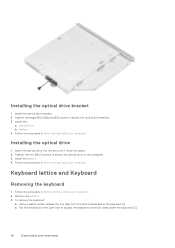
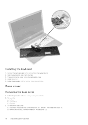
... the keyboard 1. Using a plastic scribe, release the five tabs from the slots located above the keyboard [1]. battery 4. Installing the optical drive 1. Follow the procedure in After working inside your computer. Remove the battery. 3. Install the battery. 4. Flip the keyboard on the palm rest to the computer. 3. Follow the procedure in Before working inside...
... the keyboard 1. Using a plastic scribe, release the five tabs from the slots located above the keyboard [1]. battery 4. Installing the optical drive 1. Follow the procedure in After working inside your computer. Remove the battery. 3. Install the battery. 4. Flip the keyboard on the palm rest to the computer. 3. Follow the procedure in Before working inside...
Vostro 15-3568 Owners Manual
Page 18
... the procedure in place. 4. Press along the top edges to remove it with the tabs. 3. Follow the procedure in After working inside your computer. 2. b. battery b. Disconnect the optical drive connector and lift it to lock the keyboard in Before working inside your computer. Remove the: a. To remove the base cover: a. ...
... the procedure in place. 4. Press along the top edges to remove it with the tabs. 3. Follow the procedure in After working inside your computer. 2. b. battery b. Disconnect the optical drive connector and lift it to lock the keyboard in Before working inside your computer. Remove the: a. To remove the base cover: a. ...
Vostro 15-3568 Owners Manual
Page 21
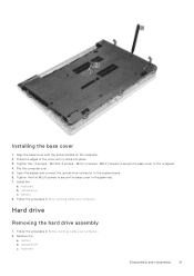
... cover to the computer. 4. Remove the: a. Press the edges of the cover until it clicks into place. 3. Installing the base cover 1. Flip the computer over. 5. battery 8. keyboard Disassembly and reassembly 21...
... cover to the computer. 4. Remove the: a. Press the edges of the cover until it clicks into place. 3. Installing the base cover 1. Flip the computer over. 5. battery 8. keyboard Disassembly and reassembly 21...
Vostro 15-3568 Owners Manual
Page 22
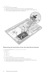
... screws that secure the hard drive bracket to remove it from the hard drive bracket [3]. 22 Disassembly and reassembly c. To remove the hard drive assembly: a. battery b. Removing the hard drive from the hard drive assembly: a. b. Lift the hard drive from the hard drive [1]. base cover e.
... screws that secure the hard drive bracket to remove it from the hard drive bracket [3]. 22 Disassembly and reassembly c. To remove the hard drive assembly: a. battery b. Removing the hard drive from the hard drive assembly: a. b. Lift the hard drive from the hard drive [1]. base cover e.
Vostro 15-3568 Owners Manual
Page 23
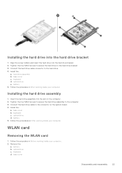
... the hard drive assembly into the hard drive bracket 1. Follow the procedure in After working inside your computer. battery 5. base cover c. Install the: a. Remove the: a. Follow the procedures in After working inside your computer Installing the hard drive assembly... 1. battery b. base cover b. Tighten the four M3L3 screws to secure the hard drive to the connector on the computer. 2. battery 5. Align the screw holders and insert the hard drive into the hard drive...
... the hard drive assembly into the hard drive bracket 1. Follow the procedure in After working inside your computer. battery 5. base cover c. Install the: a. Remove the: a. Follow the procedures in After working inside your computer Installing the hard drive assembly... 1. battery b. base cover b. Tighten the four M3L3 screws to secure the hard drive to the connector on the computer. 2. battery 5. Align the screw holders and insert the hard drive into the hard drive...
Vostro 15-3568 Owners Manual
Page 24
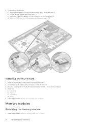
... WLAN card and tighten the M2L3 screw on the system board. 2. Disconnect the WLAN cables from the connector on the system board [4]. base cover b. keyboard c. battery 5. Remove the single M2L3 screw that secures the WLAN card [2]. Slide the WLAN card from the connectors on the WLAN card. 3. Memory modules Removing the...
... WLAN card and tighten the M2L3 screw on the system board. 2. Disconnect the WLAN cables from the connector on the system board [4]. base cover b. keyboard c. battery 5. Remove the single M2L3 screw that secures the WLAN card [2]. Slide the WLAN card from the connectors on the WLAN card. 3. Memory modules Removing the...
Vostro 15-3568 Owners Manual
Page 25
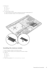
battery b. optical drive c. base cover 3. optical drive d. Follow the procedures in After working inside your computer. b. battery 4. Insert the memory module into the memory socket. 2. Remove the: a. To remove memory module: a. Installing the memory module 1. base cover b. Disassembly and reassembly 25 Remove the memory module from the system board [2]. Install the: a. keyboard c. keyboard d. Pull the clips securing the memory module until the clips secure the memory module. 3. 2. Press the memory module until the memory module pops up [1].
battery b. optical drive c. base cover 3. optical drive d. Follow the procedures in After working inside your computer. b. battery 4. Insert the memory module into the memory socket. 2. Remove the: a. To remove memory module: a. Installing the memory module 1. base cover b. Disassembly and reassembly 25 Remove the memory module from the system board [2]. Install the: a. keyboard c. keyboard d. Pull the clips securing the memory module until the clips secure the memory module. 3. 2. Press the memory module until the memory module pops up [1].
Vostro 15-3568 Owners Manual
Page 26
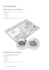
base cover 3. Insert the coin cell battery into place. 3. battery b. battery 4. keyboard d. Install the: a. keyboard c. Follow the procedures in Before working inside your computer. 26 Disassembly and reassembly Follow the procedure in After working inside your computer. 2. optical drive c. Installing the coin cell battery 1. battery b. Remove the: a. Coin-cell battery Removing the coin cell battery 1. Use a plastic scribe to lift the battery out of the slot [1,2]. Press the battery until it clicks into the battery slot. 2. optical drive d.
base cover 3. Insert the coin cell battery into place. 3. battery b. battery 4. keyboard d. Install the: a. keyboard c. Follow the procedures in Before working inside your computer. 26 Disassembly and reassembly Follow the procedure in After working inside your computer. 2. optical drive c. Installing the coin cell battery 1. battery b. Remove the: a. Coin-cell battery Removing the coin cell battery 1. Use a plastic scribe to lift the battery out of the slot [1,2]. Press the battery until it clicks into the battery slot. 2. optical drive d.
Vostro 15-3568 Owners Manual
Page 27
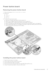
... chassis. d. Connect the system board cable to reveal the power button board beneath the hinge [3]. Remove the: a. keyboard d. Place the button board on the chassis. 2. battery b. Flip the display hinge to the power button board. Affix the system board cable to the chassis [4]. b. Affix the tape that holds the power button...
... chassis. d. Connect the system board cable to reveal the power button board beneath the hinge [3]. Remove the: a. keyboard d. Place the button board on the chassis. 2. battery b. Flip the display hinge to the power button board. Affix the system board cable to the chassis [4]. b. Affix the tape that holds the power button...
Vostro 15-3568 Owners Manual
Page 28
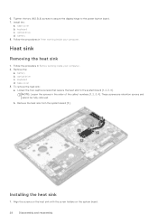
battery 8. Follow the procedures in After working inside your computer. 2. Heat sink Removing the heat sink 1. NOTE: Loosen the screws in Before working inside your computer. ... reassembly keyboard d. To remove the heat sink: a. base cover 3. Installing the heat sink 1. Install the: a. Follow the procedure in the order of the callout numbers [1, 2, 3, 4]. b. battery b.
battery 8. Follow the procedures in After working inside your computer. 2. Heat sink Removing the heat sink 1. NOTE: Loosen the screws in Before working inside your computer. ... reassembly keyboard d. To remove the heat sink: a. base cover 3. Installing the heat sink 1. Install the: a. Follow the procedure in the order of the callout numbers [1, 2, 3, 4]. b. battery b.


