
Owners Manual
Page 3
... Installing the Battery...12 Removing the Optical-Disk Drive...12 Installing the Optical-Disk Drive...12 Removing the Access Panel...12 Installing the Access Panel...13 Removing the Hard Drive...13 Installing the Hard Drive...14 Removing the Memory Module...14 Installing the... Memory Module...15 Removing the WLAN Card...15 Installing the WLAN Card...16 Removing the Keyboard...16 Installing the Keyboard...17 Removing the Palmrest Assembly...18 Installing the Palmrest Assembly...19 Removing the Coin-Cell Battery...20 Installing the Coin-cell battery...
... Installing the Battery...12 Removing the Optical-Disk Drive...12 Installing the Optical-Disk Drive...12 Removing the Access Panel...12 Installing the Access Panel...13 Removing the Hard Drive...13 Installing the Hard Drive...14 Removing the Memory Module...14 Installing the... Memory Module...15 Removing the WLAN Card...15 Installing the WLAN Card...16 Removing the Keyboard...16 Installing the Keyboard...17 Removing the Palmrest Assembly...18 Installing the Palmrest Assembly...19 Removing the Coin-Cell Battery...20 Installing the Coin-cell battery...
Owners Manual
Page 6
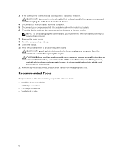
...touch an unpainted metal surface to ground the system board. NOTE: To avoid damaging the system board, you must remove the main battery before opening the display. CAUTION: Before touching anything inside your computer from the electrical outlet before you work surface. Remove any ...slots. Open the display. 10. Press the power button to dissipate static electricity, which could harm internal components. 11. Remove the main battery. 8. Disconnect all attached devices from the computer. 5. While you service the computer. 7. Recommended Tools The procedures in this document may ...
...touch an unpainted metal surface to ground the system board. NOTE: To avoid damaging the system board, you must remove the main battery before opening the display. CAUTION: Before touching anything inside your computer from the electrical outlet before you work surface. Remove any ...slots. Open the display. 10. Press the power button to dissipate static electricity, which could harm internal components. 11. Remove the main battery. 8. Disconnect all attached devices from the computer. 5. While you service the computer. 7. Recommended Tools The procedures in this document may ...

Owners Manual
Page 7
... Your Computer After you complete any replacement procedure, ensure you shut down the operating system: • In Windows 8: - Do not use only the battery designed for this particular Dell computer. Connect your computer and all attached devices to your computer and attached devices did not automatically turn off when you connect any...
... Your Computer After you complete any replacement procedure, ensure you shut down the operating system: • In Windows 8: - Do not use only the battery designed for this particular Dell computer. Connect your computer and all attached devices to your computer and attached devices did not automatically turn off when you connect any...
Owners Manual
Page 11
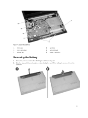
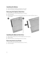
speakers 4. Follow the procedures in Before Working Inside Your Computer. 2. coin-cell battery 5. Slide the release latches outwards to unlock the battery and lift the battery to remove it from the computer. 11 system fan 2. I/O board 3. Figure 4. system board 6. System Board View 1. power connector Removing the Battery 1.
speakers 4. Follow the procedures in Before Working Inside Your Computer. 2. coin-cell battery 5. Slide the release latches outwards to unlock the battery and lift the battery to remove it from the computer. 11 system fan 2. I/O board 3. Figure 4. system board 6. System Board View 1. power connector Removing the Battery 1.
Owners Manual
Page 12
...the Optical-Disk Drive 1. Remove the screw that secures the optical-disk drive (ODD) to secure it. 2. Slide the optical-disk drive into the battery slot and press to lock in place. 2. Follow the procedures in Before Working Inside Your Computer. 2. Follow the procedures in Before Working Inside Your ...Computer. 2. Follow the procedures in After Working Inside Your Computer. Insert the battery into the chassis and tighten the screw to the computer and slide the ODD out of the computer. Remove the...
...the Optical-Disk Drive 1. Remove the screw that secures the optical-disk drive (ODD) to secure it. 2. Slide the optical-disk drive into the battery slot and press to lock in place. 2. Follow the procedures in Before Working Inside Your Computer. 2. Follow the procedures in Before Working Inside Your ...Computer. 2. Follow the procedures in After Working Inside Your Computer. Insert the battery into the chassis and tighten the screw to the computer and slide the ODD out of the computer. Remove the...
Owners Manual
Page 13
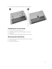
Install battery. 4. Insert the access panel into the chassis. 2. Removing the Hard Drive 1. Remove the battery. 3. 3. Installing the Access Panel 1. Follow the procedures in After Working Inside Your Computer. Follow the procedures in Before Working Inside Your Computer. 2. Loosen the screw and lift the access panel off the computer. Tighten the screw to secure the access panel to the chassis. 3. Remove the access panel. 13
Install battery. 4. Insert the access panel into the chassis. 2. Removing the Hard Drive 1. Remove the battery. 3. 3. Installing the Access Panel 1. Follow the procedures in After Working Inside Your Computer. Follow the procedures in Before Working Inside Your Computer. 2. Loosen the screw and lift the access panel off the computer. Tighten the screw to secure the access panel to the chassis. 3. Remove the access panel. 13

Owners Manual
Page 14
Slide the hard drive into the connector and then tighten the screw to secure it to the computer and slide the hard drive from the computer. battery 3. Follow the procedures in After Working Inside Your Computer. Installing the Hard Drive 1. Follow the procedures in Before Working Inside Your Computer. 2. Remove: a. access panel b. battery b. Install: a. Removing the Memory Module 1. 4. Remove the screw that secures the hard drive to the chassis. 2. access panel 14
Slide the hard drive into the connector and then tighten the screw to secure it to the computer and slide the hard drive from the computer. battery 3. Follow the procedures in After Working Inside Your Computer. Installing the Hard Drive 1. Follow the procedures in Before Working Inside Your Computer. 2. Remove: a. access panel b. battery b. Install: a. Removing the Memory Module 1. 4. Remove the screw that secures the hard drive to the chassis. 2. access panel 14

Owners Manual
Page 15
... the memory module into the socket and press to the system board. Install the access panel. 3. Removing the WLAN Card 1. access panel 3. battery b. Installing the Memory Module 1. Install the battery. 4. Follow the procedures in Before Working Inside Your Computer. 2. Remove the two connectors and the screw securing the WLAN card to lock...
... the memory module into the socket and press to the system board. Install the access panel. 3. Removing the WLAN Card 1. access panel 3. battery b. Installing the Memory Module 1. Install the battery. 4. Follow the procedures in Before Working Inside Your Computer. 2. Remove the two connectors and the screw securing the WLAN card to lock...
Owners Manual
Page 16
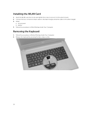
battery 4. Follow the procedures in After Working Inside Your Computer. Install: a. Release the keyboard by pressing the tabs using a scribe. 16 Insert the WLAN card into its slot and tighten the screw to secure it to the white triangle). 3. access panel b. Removing the Keyboard 1. Installing the WLAN Card 1. Connect the two connectors (black cable to the black triangle and white cable to the system board. 2. Follow the procedures in Before Working Inside Your Computer. 2.
battery 4. Follow the procedures in After Working Inside Your Computer. Install: a. Release the keyboard by pressing the tabs using a scribe. 16 Insert the WLAN card into its slot and tighten the screw to secure it to the white triangle). 3. access panel b. Removing the Keyboard 1. Installing the WLAN Card 1. Connect the two connectors (black cable to the black triangle and white cable to the system board. 2. Follow the procedures in Before Working Inside Your Computer. 2.

Owners Manual
Page 17
Install the battery. 5. Follow the procedures in place. 4. 3. Disconnect the keyboard cable from the computer. Slide the keyboard into the retaining slots. 3. Installing the Keyboard 1. Connect the keyboard cable to remove it from the system board and lift it up to the connector on the system board. 2. Slide and lift the keyboard to lock the keyboard in After Working Inside Your Computer. 17 Press the top edge to access the cable below. 4.
Install the battery. 5. Follow the procedures in place. 4. 3. Disconnect the keyboard cable from the computer. Slide the keyboard into the retaining slots. 3. Installing the Keyboard 1. Connect the keyboard cable to remove it from the system board and lift it up to the connector on the system board. 2. Slide and lift the keyboard to lock the keyboard in After Working Inside Your Computer. 17 Press the top edge to access the cable below. 4.
Owners Manual
Page 18
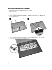
Removing the Palmrest Assembly 1. Then, release the tabs securing the base cover. 6. Remove the access panel. 4. Remove the battery. 3. Follow the procedures in Before Working Inside Your Computer. 2. Turn the computer over and remove the screws at the base of the computer. Then, disconnect the touchpad and power cables from inside the keyboard cavity. Remove the keyboard. 5. Turn the computer over and remove the screws from the system board. 18
Removing the Palmrest Assembly 1. Then, release the tabs securing the base cover. 6. Remove the access panel. 4. Remove the battery. 3. Follow the procedures in Before Working Inside Your Computer. 2. Turn the computer over and remove the screws at the base of the computer. Then, disconnect the touchpad and power cables from inside the keyboard cavity. Remove the keyboard. 5. Turn the computer over and remove the screws from the system board. 18
Owners Manual
Page 19
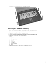
... pry up the palmrest and slide it to secure it from the computer. Turn the computer over and press at the base of the computer. 6. battery 7. keyboard b. WLAN card e. Place the palmrest on the chassis and press the notches until it clicks in After Working Inside Your Computer. 19
... pry up the palmrest and slide it to secure it from the computer. Turn the computer over and press at the base of the computer. 6. battery 7. keyboard b. WLAN card e. Place the palmrest on the chassis and press the notches until it clicks in After Working Inside Your Computer. 19
Owners Manual
Page 20
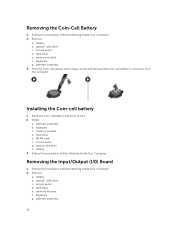
... a. keyboard g. Follow the procedures in After Working Inside Your Computer. optical- hard drive e. keyboard g. Installing the Coin-cell battery 1. memory module d. Follow the procedures in Before Working Inside Your Computer. 2. disk drive c. Remove: a. memory module f. ... f. Push the coin-cell release latch using a scribe and then pull the coin-cell battery to lock. 2. battery b. optical- optical-disk drive h. hard drive e. Removing the Coin-Cell Battery 1. disk drive c. Removing the Input/Output (I/0) Board 1. Follow the procedures in Before Working...
... a. keyboard g. Follow the procedures in After Working Inside Your Computer. optical- hard drive e. keyboard g. Installing the Coin-cell battery 1. memory module d. Follow the procedures in Before Working Inside Your Computer. 2. disk drive c. Remove: a. memory module f. ... f. Push the coin-cell release latch using a scribe and then pull the coin-cell battery to lock. 2. battery b. optical- optical-disk drive h. hard drive e. Removing the Coin-Cell Battery 1. disk drive c. Removing the Input/Output (I/0) Board 1. Follow the procedures in Before Working...
Owners Manual
Page 21
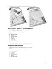
Connect the I /O board from the computer. battery 4. Removing the Speakers 1. Follow the procedures in After Working Inside Your Computer. keyboard g. hard drive e. access panel g. disk drive c. Install: a. palmrest assembly b. keyboard c. Disconnect...- memory module f. 3. Installing the Input/Output (I /O board into the chassis. 2. optical-disk drive h. Remove: a. hard drive e. access panel d. palmrest assembly 21 Insert the I /O) Board 1. battery b. memory module d. Follow the procedures in Before Working Inside Your Computer. 2. WLAN card f.
Connect the I /O board from the computer. battery 4. Removing the Speakers 1. Follow the procedures in After Working Inside Your Computer. keyboard g. hard drive e. access panel g. disk drive c. Install: a. palmrest assembly b. keyboard c. Disconnect...- memory module f. 3. Installing the Input/Output (I /O board into the chassis. 2. optical-disk drive h. Remove: a. hard drive e. access panel d. palmrest assembly 21 Insert the I /O) Board 1. battery b. memory module d. Follow the procedures in Before Working Inside Your Computer. 2. WLAN card f.
Owners Manual
Page 23
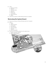
optical-disk drive h. battery 4. memory module f. WLAN card f. Follow the procedures in Before Working Inside Your Computer. 2. battery b. hard-disk drive e. Disconnect the following cables from the system board: a. optical-disk drive c. palmrest assembly 3. palmrest assembly b. access panel d. 3. Remove: a. display (LVDS) cables (2) 23 hard drive e. access panel g. keyboard c. Removing the System Board 1. memory module d. speaker and power cable (1) b. Install: a. keyboard g. Follow the procedures in After Working Inside Your Computer.
optical-disk drive h. battery 4. memory module f. WLAN card f. Follow the procedures in Before Working Inside Your Computer. 2. battery b. hard-disk drive e. Disconnect the following cables from the system board: a. optical-disk drive c. palmrest assembly 3. palmrest assembly b. access panel d. 3. Remove: a. display (LVDS) cables (2) 23 hard drive e. access panel g. keyboard c. Removing the System Board 1. memory module d. speaker and power cable (1) b. Install: a. keyboard g. Follow the procedures in After Working Inside Your Computer.

Owners Manual
Page 25
keyboard c. hard drive e. Follow the procedures in Before Working Inside Your Computer. 2. battery b. palmrest assembly h. Connect the power connector to the computer. 7. palmrest assembly b. Install: a. Remove: a. optical- keyboard g. Tighten the screws to secure the system board to the ... module f. Removing the Display Assembly 1. system board 3. Un-thread the WLAN cable and remove the screws that secure the display panel to the chassis. 25 5. battery 8. hard drive e. access panel f.
keyboard c. hard drive e. Follow the procedures in Before Working Inside Your Computer. 2. battery b. palmrest assembly h. Connect the power connector to the computer. 7. palmrest assembly b. Install: a. Remove: a. optical- keyboard g. Tighten the screws to secure the system board to the ... module f. Removing the Display Assembly 1. system board 3. Un-thread the WLAN cable and remove the screws that secure the display panel to the chassis. 25 5. battery 8. hard drive e. access panel f.
Owners Manual
Page 28
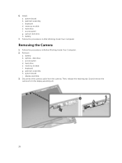
... assembly (2). 28 keyboard d. optical-disk drive h. optical- memory module f. access panel g. system board b. Follow the procedures in Before Working Inside Your Computer. 2. Removing the Camera 1. battery b. display assembly 3. hard drive e. palmrest assembly h. Then, release the retaining tab (1) and remove the camera from the camera. Install: a. Follow the procedures in After Working...
... assembly (2). 28 keyboard d. optical-disk drive h. optical- memory module f. access panel g. system board b. Follow the procedures in Before Working Inside Your Computer. 2. Removing the Camera 1. battery b. display assembly 3. hard drive e. palmrest assembly h. Then, release the retaining tab (1) and remove the camera from the camera. Install: a. Follow the procedures in After Working...
Owners Manual
Page 29
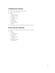
Install: a. display assembly b. hard drive f. access panel h. battery b. hard drive e. system board 29 optical-disk drive i. palmrest assembly h. palmrest assembly c. optical-disk drive c. access panel d. Follow the procedures in After Working ... Your Computer. memory module f. Insert the camera into the display assembly. 2. Follow the procedures in Before Working Inside Your Computer. 2. keyboard g. WLAN card g. battery 4. Removing the Heatsink 1. memory module e. Installing the Camera 1. keyboard d. Connect the camera cable. 3. Remove: a.
Install: a. display assembly b. hard drive f. access panel h. battery b. hard drive e. system board 29 optical-disk drive i. palmrest assembly h. palmrest assembly c. optical-disk drive c. access panel d. Follow the procedures in After Working ... Your Computer. memory module f. Insert the camera into the display assembly. 2. Follow the procedures in Before Working Inside Your Computer. 2. keyboard g. WLAN card g. battery 4. Removing the Heatsink 1. memory module e. Installing the Camera 1. keyboard d. Connect the camera cable. 3. Remove: a.

Owners Manual
Page 30
Install: a. palmrest assembly c. memory module e. hard drive f. optical-disk drive i. battery b. memory module f. keyboard g. Then, remove the screws that secure the heatsink to the system board and lift it to the system board. 2. Installing the Heatsink 1. .... Insert the heatsink and tighten the screws to the system board. 3. Connect the system fan's cable to secure it off the board. keyboard d. access panel h. battery 4. Follow the procedures in Before Working Inside Your Computer. 2. Remove: a. hard drive e.
Install: a. palmrest assembly c. memory module e. hard drive f. optical-disk drive i. battery b. memory module f. keyboard g. Then, remove the screws that secure the heatsink to the system board and lift it to the system board. 2. Installing the Heatsink 1. .... Insert the heatsink and tighten the screws to the system board. 3. Connect the system fan's cable to secure it off the board. keyboard d. access panel h. battery 4. Follow the procedures in Before Working Inside Your Computer. 2. Remove: a. hard drive e.
Owners Manual
Page 31
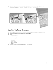
... slot on the chassis and guide the cable into the retaining tabs. 2. WLAN card f. palmrest assembly b. hard drive e. memory module d. Installing the Power Connector 1. keyboard c. battery 4. optical-disk drive h. Then, lift the power connector and cable off the computer. Disconnect the power connector from the system board (1) and un-thread the...
... slot on the chassis and guide the cable into the retaining tabs. 2. WLAN card f. palmrest assembly b. hard drive e. memory module d. Installing the Power Connector 1. keyboard c. battery 4. optical-disk drive h. Then, lift the power connector and cable off the computer. Disconnect the power connector from the system board (1) and un-thread the...

