Service Manual
Page 19
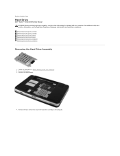
.... 4. Remove the four screws that secure the hard drive assembly to Contents Page Hard Drive Dell™ Vostro™ 1014/1015 Service Manual WARNING: Before working inside your computer, read the safety information that shipped with your computer. For additional safety best practices information, see the Regulatory Compliance Homepage at www.dell.com/regulatory_compliance. Remove the battery. 3. Back...
.... 4. Remove the four screws that secure the hard drive assembly to Contents Page Hard Drive Dell™ Vostro™ 1014/1015 Service Manual WARNING: Before working inside your computer, read the safety information that shipped with your computer. For additional safety best practices information, see the Regulatory Compliance Homepage at www.dell.com/regulatory_compliance. Remove the battery. 3. Back...
Service Manual
Page 20
Replacing the Hard Drive Assembly Perform the above steps in the reverse order to release the hard drive interposer from the computer. Removing the Hard Drive Bracket 1. Remove the battery. 3. Remove the access panel. 4. Follow the procedures in the computer. Remove the hard drive. 5. Lift the hard drive assembly from the connector on the system board. 6. Pull the mylar tab towards the hard drive assembly to replace the hard drive assembly in Before Working Inside Your Computer. 2.
Replacing the Hard Drive Assembly Perform the above steps in the reverse order to release the hard drive interposer from the computer. Removing the Hard Drive Bracket 1. Remove the battery. 3. Remove the access panel. 4. Follow the procedures in the computer. Remove the hard drive. 5. Lift the hard drive assembly from the connector on the system board. 6. Pull the mylar tab towards the hard drive assembly to replace the hard drive assembly in Before Working Inside Your Computer. 2.

Service Manual
Page 21
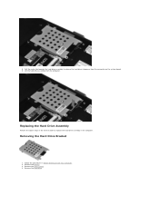
Remove the four screws, two on either sides of the bracket, that secure the hard drive to the hard drive bracket. 6. 5. Replacing the Hard Drive Bracket Lift the bracket from the hard drive.
Remove the four screws, two on either sides of the bracket, that secure the hard drive to the hard drive bracket. 6. 5. Replacing the Hard Drive Bracket Lift the bracket from the hard drive.
Service Manual
Page 22
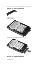
Removing the Hard Drive Interposer 1. Replacing the Hard Drive Interposer Perform the above step in the reverse order to replace the hard drive interposer. Perform the above steps in the reverse order to replace the hard drive into the hard drive bracket. Follow the procedures in Before Working Inside Your Computer. 2. Back to Contents Page Remove the hard drive. 5. Tugging gently, remove the hard drive interposer from the hard drive. Remove the battery. 3. Remove the access panel. 4.
Removing the Hard Drive Interposer 1. Replacing the Hard Drive Interposer Perform the above step in the reverse order to replace the hard drive interposer. Perform the above steps in the reverse order to replace the hard drive into the hard drive bracket. Follow the procedures in Before Working Inside Your Computer. 2. Back to Contents Page Remove the hard drive. 5. Tugging gently, remove the hard drive interposer from the hard drive. Remove the battery. 3. Remove the access panel. 4.
Service Manual
Page 30
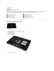
...procedures in Before Working Inside Your Computer. 2. Back to Contents Page Display Dell™ Vostro™ 1014/1015 Service Manual WARNING: Before working inside your computer, read the safety ...Replacing the Display Assembly Removing the Display Bezel Replacing the Display Bezel Removing the LED Display Panel Replacing the LED Display Panel Removing the Display Camera Replacing the Display Camera Removing the Display Inverter Cable Replacing the Display Inverter Cable Removing the Display Assembly 1. Remove the WLAN card. 6. Disconnect the wireless cables. Remove the hard drive...
...procedures in Before Working Inside Your Computer. 2. Back to Contents Page Display Dell™ Vostro™ 1014/1015 Service Manual WARNING: Before working inside your computer, read the safety ...Replacing the Display Assembly Removing the Display Bezel Replacing the Display Bezel Removing the LED Display Panel Replacing the LED Display Panel Removing the Display Camera Replacing the Display Camera Removing the Display Inverter Cable Replacing the Display Inverter Cable Removing the Display Assembly 1. Remove the WLAN card. 6. Disconnect the wireless cables. Remove the hard drive...
Service Manual
Page 33
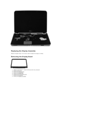
Remove the control panel cover. 7. Remove the battery. 3. Remove the display assembly. Remove the keyboard. 8. Remove the access panel. 4. Remove the WLAN card. 6. Follow the procedures in the reverse order to replace the display assembly. Replacing the Display Assembly Perform the above steps in Before Working Inside Your Computer. 2. Remove the hard drive. 5. Removing the Display Bezel 1.
Remove the control panel cover. 7. Remove the battery. 3. Remove the display assembly. Remove the keyboard. 8. Remove the access panel. 4. Remove the WLAN card. 6. Follow the procedures in the reverse order to replace the display assembly. Replacing the Display Assembly Perform the above steps in Before Working Inside Your Computer. 2. Remove the hard drive. 5. Removing the Display Bezel 1.

Service Manual
Page 35
Remove the display bezel. Remove the WLAN card. 6. Remove the keyboard. Removing the Display LED Panel 1. Remove the access panel. 4. 11. Remove the hard drive. 5. Remove the battery. 3. Replacing the Display Bezel Perform the above steps in Before Working Inside Your Computer. 2. Remove the control panel cover. 7. Follow the procedures in the reverse order to replace the display bezel into the display assembly.
Remove the display bezel. Remove the WLAN card. 6. Remove the keyboard. Removing the Display LED Panel 1. Remove the access panel. 4. 11. Remove the hard drive. 5. Remove the battery. 3. Replacing the Display Bezel Perform the above steps in Before Working Inside Your Computer. 2. Remove the control panel cover. 7. Follow the procedures in the reverse order to replace the display bezel into the display assembly.

Service Manual
Page 37
Replacing the Display LED Panel Perform the above steps in Before Working Inside Your Computer. 2. Remove the hard drive. 5. Remove the display bezel. 10. Lift the display LED panel from the display assembly. Remove the keyboard. 8. Follow the procedures in the reverse to replace the display LED panel. Remove the battery. 3. Remove the WLAN card. 6. Remove the control panel cover. 7. Remove the display LED panel. 12. Remove the access panel. 4. Removing the Display Camera 1. Remove the display assembly. 9.
Replacing the Display LED Panel Perform the above steps in Before Working Inside Your Computer. 2. Remove the hard drive. 5. Remove the display bezel. 10. Lift the display LED panel from the display assembly. Remove the keyboard. 8. Follow the procedures in the reverse to replace the display LED panel. Remove the battery. 3. Remove the WLAN card. 6. Remove the control panel cover. 7. Remove the display LED panel. 12. Remove the access panel. 4. Removing the Display Camera 1. Remove the display assembly. 9.

Service Manual
Page 38
... 8. Remove the display bezel. 10. Remove the two screws that secure the bracket to the display assembly. 12. Remove the hard drive. 5. Remove the control panel cover. 7. Remove the access panel. 4. Replacing the Display Camera Perform the above steps in Before Working Inside Your Computer. 2. Remove the display LED panel. Remove the display... screws that secure the display camera to the display camera. Remove the WLAN card. 6. Remove the battery. 3. Lift the display camera from there to replace the display camera into its bracket, and from the display assembly. 13.
... 8. Remove the display bezel. 10. Remove the two screws that secure the bracket to the display assembly. 12. Remove the hard drive. 5. Remove the control panel cover. 7. Remove the access panel. 4. Replacing the Display Camera Perform the above steps in Before Working Inside Your Computer. 2. Remove the display LED panel. Remove the display... screws that secure the display camera to the display camera. Remove the WLAN card. 6. Remove the battery. 3. Lift the display camera from there to replace the display camera into its bracket, and from the display assembly. 13.
Service Manual
Page 69
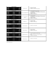
... the computer with both modules. 3. Test the other slot with just the hard drive and just the optical drive. 3. Reseat the memory. 2. Replace the system board. Replace the system board. Option ROM error 1. Replace the system board. Replace the memory. 4. Replace the system board. Memory compatibility error 1. Replace the system board. Memory is causing the failure. 4. If two modules...
... the computer with both modules. 3. Test the other slot with just the hard drive and just the optical drive. 3. Reseat the memory. 2. Replace the system board. Replace the system board. Option ROM error 1. Replace the system board. Replace the memory. 4. Replace the system board. Memory compatibility error 1. Replace the system board. Memory is causing the failure. 4. If two modules...
Service Manual
Page 70
Back to Contents Page Adding and Replacing Parts Dell™ Vostro™ 1014/1015 Service Manual ExpressCard Battery Access Panel Memory Control Panel Cover Display Assembly Processor Fan I/O Board System Board Heat Sink Back to Contents Page Memory Card Optical Drive Hard Drive WLAN Card Keyboard Palm Rest Coin-Cell Battery Internal Card with Bluetooth® Wireless Technology Speaker Processor
Back to Contents Page Adding and Replacing Parts Dell™ Vostro™ 1014/1015 Service Manual ExpressCard Battery Access Panel Memory Control Panel Cover Display Assembly Processor Fan I/O Board System Board Heat Sink Back to Contents Page Memory Card Optical Drive Hard Drive WLAN Card Keyboard Palm Rest Coin-Cell Battery Internal Card with Bluetooth® Wireless Technology Speaker Processor
Service Manual
Page 75
... CAUTION: Handle components and cards with the product. As you turn the computer upside-down on Your Computer Dell™ Vostro™ 1014/1015 Service Manual Before Working Inside Your Computer Recommended Tools Turning Off Your Computer After Working Inside Your Computer ... devices from being scratched. 2. CAUTION: Many repairs may only be replaced or-if purchased separately-installed by your computer (see Hard Drive). Hold a component such as the metal at www.dell.com/regulatory_compliance. Ensure that both connectors are disconnecting this document assumes that...
... CAUTION: Handle components and cards with the product. As you turn the computer upside-down on Your Computer Dell™ Vostro™ 1014/1015 Service Manual Before Working Inside Your Computer Recommended Tools Turning Off Your Computer After Working Inside Your Computer ... devices from being scratched. 2. CAUTION: Many repairs may only be replaced or-if purchased separately-installed by your computer (see Hard Drive). Hold a component such as the metal at www.dell.com/regulatory_compliance. Ensure that both connectors are disconnecting this document assumes that...


