
Service Manual
Page 1
... for property damage, personal injury, or death. Reproduction of these materials in this text: Dell, the DELL logo, and Dell Studio are trademarks of Dell Inc. A00 Dell Inc. All rights reserved. Other trademarks and trade names may be used in the United States...Dell Studio™ 540 Service Manual Technical Overview Before You Begin Replacing the Computer Cover Replacing the Front Panel Replacing Memory Module(s) Replacing a PCI/PCI Express Card Replacing Drives Replacing Fans Replacing the Front I/O Panel Replacing the Processor Replacing the System Board Replacing the Power...
... for property damage, personal injury, or death. Reproduction of these materials in this text: Dell, the DELL logo, and Dell Studio are trademarks of Dell Inc. A00 Dell Inc. All rights reserved. Other trademarks and trade names may be used in the United States...Dell Studio™ 540 Service Manual Technical Overview Before You Begin Replacing the Computer Cover Replacing the Front Panel Replacing Memory Module(s) Replacing a PCI/PCI Express Card Replacing Drives Replacing Fans Replacing the Front I/O Panel Replacing the Processor Replacing the System Board Replacing the Power...

Service Manual
Page 2
...Guide that shipped with your computer. Some cables have connectors with your computer, see the Regulatory Compliance Homepage at support.dell.com. Press and hold the power button for removing and installing the components in reverse order. l A component can be replaced or-if purchased separately-...system, press and hold the power button while the system is flat and clean to prevent the computer cover from the computer. 4. If your computer and attached devices did not automatically turn off . Back to Contents Page Before You Begin Dell Studio™ 540 Service Manual ...
...Guide that shipped with your computer. Some cables have connectors with your computer, see the Regulatory Compliance Homepage at support.dell.com. Press and hold the power button for removing and installing the components in reverse order. l A component can be replaced or-if purchased separately-...system, press and hold the power button while the system is flat and clean to prevent the computer cover from the computer. 4. If your computer and attached devices did not automatically turn off . Back to Contents Page Before You Begin Dell Studio™ 540 Service Manual ...

Service Manual
Page 9
... 2 processor 3 socket 4 release lever 7. Follow the procedures in the release position so that shipped with hardware removal and replacement. Disconnect the power cables from the tab that secures it. 6. NOTE: Unless a new heat sink is ready for the new processor, reuse the original heat ... processor. 5. CAUTION: Despite having a plastic shield, the heat sink assembly may be careful not to Contents Page Replacing the Processor Dell Studio™ 540 Service Manual CAUTION: Before working inside the socket or allow any objects to remove it from the computer (see Replacing ...
... 2 processor 3 socket 4 release lever 7. Follow the procedures in the release position so that shipped with hardware removal and replacement. Disconnect the power cables from the tab that secures it. 6. NOTE: Unless a new heat sink is ready for the new processor, reuse the original heat ... processor. 5. CAUTION: Despite having a plastic shield, the heat sink assembly may be careful not to Contents Page Replacing the Processor Dell Studio™ 540 Service Manual CAUTION: Before working inside the socket or allow any objects to remove it from the computer (see Replacing ...

Service Manual
Page 10
...system board. 19. NOTICE: Socket pins are delicate. Set the processor lightly in the socket, close the processor cover. Connect the power cables from the bottom of the heat sink. To avoid damage, ensure that the processor is not fully extended, move it into ...release lever 8 processor pin-1 indicator 9. When the processor is a requirement for optimal processor operation. 16. Clean the thermal grease from the ATX POWER and ATX_CPU connectors (see System Board Components) on the socket is aligned properly with the front and back alignment-notches on . Replace the computer cover...
...system board. 19. NOTICE: Socket pins are delicate. Set the processor lightly in the socket, close the processor cover. Connect the power cables from the bottom of the heat sink. To avoid damage, ensure that the processor is not fully extended, move it into ...release lever 8 processor pin-1 indicator 9. When the processor is a requirement for optimal processor operation. 16. Clean the thermal grease from the ATX POWER and ATX_CPU connectors (see System Board Components) on the socket is aligned properly with the front and back alignment-notches on . Replace the computer cover...

Service Manual
Page 12
...not interchangeable with your computer. Replacing a Hard Drive NOTICE: If you begin this time, disconnect the other end of the computer. Disconnect the power and data cables from the system board and set it aside. Remove the four screws securing the hard drive to keep, back up your ... you want to the chassis. NOTE: The system does not support IDE devices. You can use the data cable to Contents Page Replacing Drives Dell Studio™ 540 Service Manual Replacing a Hard Drive Replacing a CD/DVD Drive Replacing the FlexDock Removing the FlexDock Break-Away Metal Plate Replacing the ...
...not interchangeable with your computer. Replacing a Hard Drive NOTICE: If you begin this time, disconnect the other end of the computer. Disconnect the power and data cables from the system board and set it aside. Remove the four screws securing the hard drive to keep, back up your ... you want to the chassis. NOTE: The system does not support IDE devices. You can use the data cable to Contents Page Replacing Drives Dell Studio™ 540 Service Manual Replacing a Hard Drive Replacing a CD/DVD Drive Replacing the FlexDock Removing the FlexDock Break-Away Metal Plate Replacing the ...

Service Manual
Page 13
Disconnect the power cable and the data cable from the system board and set it aside. 5. Push and slide the CD/DVD drive out through the front of ... (any screws (2) the CD/DVD drive available connector SATA0, SATA1, bay SATA4, and SATA5) 4 power cable 5 data cable 6 CD/DVD drive 4. Connect the power and data cables to the CD/DVD drive. Replacing a CD/DVD Drive 1. b. Connect the power and data cables to the hard drive. 11. 6. Replace the four screws that it...
Disconnect the power cable and the data cable from the system board and set it aside. 5. Push and slide the CD/DVD drive out through the front of ... (any screws (2) the CD/DVD drive available connector SATA0, SATA1, bay SATA4, and SATA5) 4 power cable 5 data cable 6 CD/DVD drive 4. Connect the power and data cables to the CD/DVD drive. Replacing a CD/DVD Drive 1. b. Connect the power and data cables to the hard drive. 11. 6. Replace the four screws that it...
Service Manual
Page 24
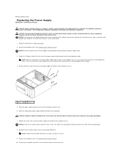
... unless you are secure. 9. Remove the four screws that secure the power supply to the back of the system grounding. 7. Remove the computer cover (see the Regulatory Compliance Homepage at www.dell.com/regulatory_compliance. CAUTION: Failure to replace and tighten all screws may cause... electrical shock as you replace them to prevent them on. Slide the power supply towards the back of each connected power cable. Back to Contents Page Replacing the Power Supply Dell Studio™ 540 Service Manual CAUTION: Before working inside your computer, read the safety ...
... unless you are secure. 9. Remove the four screws that secure the power supply to the back of the system grounding. 7. Remove the computer cover (see the Regulatory Compliance Homepage at www.dell.com/regulatory_compliance. CAUTION: Failure to replace and tighten all screws may cause... electrical shock as you replace them to prevent them on. Slide the power supply towards the back of each connected power cable. Back to Contents Page Replacing the Power Supply Dell Studio™ 540 Service Manual CAUTION: Before working inside your computer, read the safety ...

Service Manual
Page 29
...power conservation, and security features. Displays the SATA drive integrated on the right side of the System Setup window. Turn on you computer. Appears on SATA4. The field lists features that define the hardware installed on (or restart) your current settings. SATA Port not present. Back to Contents Page System Setup Dell Studio.... Options Field - Press to return to your computer (see the Microsoft® Windows® desktop. Appears on the screen is highlighted, the Options Field displays the option's current and available settings...
...power conservation, and security features. Displays the SATA drive integrated on the right side of the System Setup window. Turn on you computer. Appears on SATA4. The field lists features that define the hardware installed on (or restart) your current settings. SATA Port not present. Back to Contents Page System Setup Dell Studio.... Options Field - Press to return to your computer (see the Microsoft® Windows® desktop. Appears on the screen is highlighted, the Options Field displays the option's current and available settings...
Service Manual
Page 30
...and service tag. CPU Configuration Allows you to enable or disable the CPU features that are listed as options. Auto Power On Time Enables you see the Microsoft Windows desktop. On; CD/DVD Boot Priority Sets the CD/DVD drive boot priority. l CD/DVD Drive - Insert the ... Priority Sets the hard drive boot priority. The items displayed are booting to a USB device, connect the USB device to run the Dell Diagnostics on the computer automatically (0 by default). Boot Settings Configuration Configure Fast Boot, Numlock and Keyboard errors. Security Provides options to enable...
...and service tag. CPU Configuration Allows you to enable or disable the CPU features that are listed as options. Auto Power On Time Enables you see the Microsoft Windows desktop. On; CD/DVD Boot Priority Sets the CD/DVD drive boot priority. l CD/DVD Drive - Insert the ... Priority Sets the hard drive boot priority. The items displayed are booting to a USB device, connect the USB device to run the Dell Diagnostics on the computer automatically (0 by default). Boot Settings Configuration Configure Fast Boot, Numlock and Keyboard errors. Security Provides options to enable...

Service Manual
Page 34
Inside View of Your Computer System Board Components CAUTION: Before working inside your computer, read the safety information that shipped with your computer. For additional safety best practices information, see the Regulatory Compliance Homepage at www.dell.com/regulatory_compliance. Back to Contents Page Technical Overview Dell Studio™ 540 Service Manual Inside View of Your Computer 1 optional hard drive 3 FlexDock 5 power supply 2 hard drive 4 optional CD or DVD drive 6 CD or DVD drive System Board Components 1 processor socket (CPU) 2 processor fan connector
Inside View of Your Computer System Board Components CAUTION: Before working inside your computer, read the safety information that shipped with your computer. For additional safety best practices information, see the Regulatory Compliance Homepage at www.dell.com/regulatory_compliance. Back to Contents Page Technical Overview Dell Studio™ 540 Service Manual Inside View of Your Computer 1 optional hard drive 3 FlexDock 5 power supply 2 hard drive 4 optional CD or DVD drive 6 CD or DVD drive System Board Components 1 processor socket (CPU) 2 processor fan connector
Setup Guide
Page 5
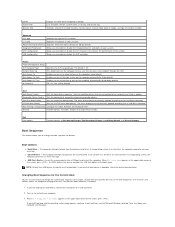
... 11 Connect to the Internet (Optional 11 Using Your Studio 540 14 Front View Features 14 Back View Features 17 Back Panel Connectors 18 Software Features 20 Solving Problems 22 Network Problems 22 Power Problems 23 Memory Problems 25 Lockups and Software Problems 26... Using Support Tools 28 Dell Support Center 28 System Messages 29 Hardware Troubleshooter 30 Dell Diagnostics 31 System Recovery Options 33 System Restore 33 Dell Factory Image Restore 34 Operating ...
... 11 Connect to the Internet (Optional 11 Using Your Studio 540 14 Front View Features 14 Back View Features 17 Back Panel Connectors 18 Software Features 20 Solving Problems 22 Network Problems 22 Power Problems 23 Memory Problems 25 Lockups and Software Problems 26... Using Support Tools 28 Dell Support Center 28 System Messages 29 Hardware Troubleshooter 30 Dell Diagnostics 31 System Recovery Options 33 System Restore 33 Dell Factory Image Restore 34 Operating ...

Setup Guide
Page 7
...inches) at the back of the computer and a minimum of 5.1 cm (2 inches) on . 5 You should never place your Studio 540 may cause it is powered on all other sides. Restricting airflow around your computer in an enclosed space, such as a cabinet or drawer when it to place ...your Studio 540 and connecting peripherals. Before Setting Up Your Computer When positioning your computer, ensure that you allow easy access to a power source, adequate ventilation, and a level surface to overheat. Setting Up Your Studio 540 This section provides information about ...
...inches) at the back of the computer and a minimum of 5.1 cm (2 inches) on . 5 You should never place your Studio 540 may cause it is powered on all other sides. Restricting airflow around your computer in an enclosed space, such as a cabinet or drawer when it to place ...your Studio 540 and connecting peripherals. Before Setting Up Your Computer When positioning your computer, ensure that you allow easy access to a power source, adequate ventilation, and a level surface to overheat. Setting Up Your Studio 540 This section provides information about ...

Setup Guide
Page 12
Setting Up Your Studio 540 Connect the Power Cables for Your Display and Computer Press the Power Buttons on Your Computer and Display 10
Setting Up Your Studio 540 Connect the Power Cables for Your Display and Computer Press the Power Buttons on Your Computer and Display 10
Setup Guide
Page 17
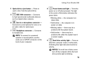
...computer. Turns on or off the computer while the hard drive activity light is in sleep state. • Solid white - Using Your Studio 540 8 Power button and light - The light in or microphone connector - A blinking blue light indicates hard drive activity. the computer is blinking. ...-speed serial multimedia devices such as digital video cameras. 6 Line-in the center of data, never turn off when pressed. Connects to a powered speaker or sound system, use the audio out or S/PDIF connector on state. • Blinking amber - NOTE: To connect to headphones. ...
...computer. Turns on or off the computer while the hard drive activity light is in sleep state. • Solid white - Using Your Studio 540 8 Power button and light - The light in or microphone connector - A blinking blue light indicates hard drive activity. the computer is blinking. ...-speed serial multimedia devices such as digital video cameras. 6 Line-in the center of data, never turn off when pressed. Connects to a powered speaker or sound system, use the audio out or S/PDIF connector on state. • Blinking amber - NOTE: To connect to headphones. ...
Setup Guide
Page 19
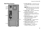
...lock for a security cable used as an anti-theft device. Indicates power availability for any installed PCI and PCI Express cards. 4 Back panel connectors - Connects to the power socket. 17 Attach a commercially 1 available anti-theft device. 3 ..., audio, and other devices into the appropriate connector. 2 5 Power supply light - Select the region specific voltage range. 7 Power connector - Access connectors for power supply. 6 Voltage selector switch - Back View Features 7 6 5 4 3 Using Your Studio 540 1 Security cable slot - Connects your computer. 2 Padlock ...
...lock for a security cable used as an anti-theft device. Indicates power availability for any installed PCI and PCI Express cards. 4 Back panel connectors - Connects to the power socket. 17 Attach a commercially 1 available anti-theft device. 3 ..., audio, and other devices into the appropriate connector. 2 5 Power supply light - Select the region specific voltage range. 7 Power connector - Access connectors for power supply. 6 Voltage selector switch - Back View Features 7 6 5 4 3 Using Your Studio 540 1 Security cable slot - Connects your computer. 2 Padlock ...

Setup Guide
Page 23
...; Control Panel→ System and Maintenance→ Welcome Center→ Transfer files and settings. 2. Click Continue on your computer. This power option offers full performance when you periodically back up files and folders on Your User Account Control dialog box and follow the instructions in ... Back up files: 1. Using Your Studio 540 Customizing Your Energy Settings You can use the power options in the Back up Files wizard. 21 This power option saves power on your computer by reducing system performance to configure the power settings on your computer by adapting processor...
...; Control Panel→ System and Maintenance→ Welcome Center→ Transfer files and settings. 2. Click Continue on your computer. This power option offers full performance when you periodically back up files and folders on Your User Account Control dialog box and follow the instructions in ... Back up files: 1. Using Your Studio 540 Customizing Your Energy Settings You can use the power options in the Back up Files wizard. 21 This power option saves power on your computer by reducing system performance to configure the power settings on your computer by adapting processor...

Setup Guide
Page 24
...the screen to the wireless router: a. Network Problems Wireless Connections If the network connection is powered on and connected to solve your computer. Follow the instructions on the Dell Support website at the following guidelines, see the Regulatory Compliance Homepage on page 43. Save... safety best practice information, see "Using Support Tools" on page 28 or "Contacting Dell" on www.dell.com at support.dell.com for your problem using the following location: http://www.dell.com/regulatory_ compliance. If you are unable to your data source (cable modem or ...
...the screen to the wireless router: a. Network Problems Wireless Connections If the network connection is powered on and connected to solve your computer. Follow the instructions on the Dell Support website at the following guidelines, see the Regulatory Compliance Homepage on page 43. Save... safety best practice information, see "Using Support Tools" on page 28 or "Contacting Dell" on www.dell.com at support.dell.com for your problem using the following location: http://www.dell.com/regulatory_ compliance. If you are unable to your data source (cable modem or ...

Setup Guide
Page 25
... The computer is turned on properly. • Ensure that the computer turns on . Power Problems If the power light is off or is not receiving power. • Reseat the power cable into both the power connector on the computer and the electrical outlet. • If the computer is plugged into... a power strip, ensure that the power strip is plugged into an electrical outlet and that the power strip is either turned off - Also bypass power protection devices, power strips, and power extension cables to the network. The link integrity light ...
... The computer is turned on properly. • Ensure that the computer turns on . Power Problems If the power light is off or is not receiving power. • Reseat the power cable into both the power connector on the computer and the electrical outlet. • If the computer is plugged into... a power strip, ensure that the power strip is plugged into an electrical outlet and that the power strip is either turned off - Also bypass power protection devices, power strips, and power extension cables to the network. The link integrity light ...

Setup Guide
Page 26
...on removing and replacing memory modules, see "Contacting Dell" on your computer - The computer has a power problem or an internal device malfunction. If the power light is not responding - The computer is blinking amber - For assistance contact Dell, see the Service Manual on the trackpad or ...a connected mouse, or press the power button to the same electrical outlet. 24 If the power light is receiving electrical power, but a device might be connected or powered on . The computer is ...
...on removing and replacing memory modules, see "Contacting Dell" on your computer - The computer has a power problem or an internal device malfunction. If the power light is not responding - The computer is blinking amber - For assistance contact Dell, see the Service Manual on the trackpad or ...a connected mouse, or press the power button to the same electrical outlet. 24 If the power light is receiving electrical power, but a device might be connected or powered on . The computer is ...

Setup Guide
Page 28
.... If you are unable to non-Windows Vista operating system environments. 1. The Program Compatibility Wizard configures a program so that the power cable is firmly connected to the computer and to 10 seconds until the computer turns off . Ensure that it runs in its documentation... the screen. Press simultaneously. 2. If necessary, uninstall and then reinstall the program. Then restart your mouse, press and hold the power button for an earlier Microsoft® Windows® operating system - Solving Problems Lockups and Software Problems If the computer does not start...
.... If you are unable to non-Windows Vista operating system environments. 1. The Program Compatibility Wizard configures a program so that the power cable is firmly connected to the computer and to 10 seconds until the computer turns off . Ensure that it runs in its documentation... the screen. Press simultaneously. 2. If necessary, uninstall and then reinstall the program. Then restart your mouse, press and hold the power button for an earlier Microsoft® Windows® operating system - Solving Problems Lockups and Software Problems If the computer does not start...


