
Service Manual
Page 1
... potential damage to hardware or loss of data and tells you make better use of Dell Inc.; Microsoft a n d Windows are trademarks of your computer. Dell Studio™ 540 Service Manual Technical Overview Before You Begin Replacing the Computer Cover Replacing the... Front Panel Replacing Memory Module(s) Replacing a PCI/PCI Express Card Replacing Drives Replacing Fans Replacing the Front I/O Panel Replacing the Processor Replacing the System Board Replacing the Power...
... potential damage to hardware or loss of data and tells you make better use of Dell Inc.; Microsoft a n d Windows are trademarks of your computer. Dell Studio™ 540 Service Manual Technical Overview Before You Begin Replacing the Computer Cover Replacing the... Front Panel Replacing Memory Module(s) Replacing a PCI/PCI Express Card Replacing Drives Replacing Fans Replacing the Front I/O Panel Replacing the Processor Replacing the System Board Replacing the Power...

Service Manual
Page 2
...: To avoid damaging the computer, perform the following conditions exist: l You have connectors with your computer. Press and hold the power button for about 4 seconds to Contents Page Before You Begin Dell Studio™ 540 Service Manual Technical Specifications Recommended Tools Turning Off Your Computer Safety Instructions This chapter provides procedures for removing...
...: To avoid damaging the computer, perform the following conditions exist: l You have connectors with your computer. Press and hold the power button for about 4 seconds to Contents Page Before You Begin Dell Studio™ 540 Service Manual Technical Specifications Recommended Tools Turning Off Your Computer Safety Instructions This chapter provides procedures for removing...

Service Manual
Page 9
...socket is required for the new processor. Unpack the new processor, be very hot during normal operation. Back to Contents Page Replacing the Processor Dell Studio™ 540 Service Manual CAUTION: Before working inside the socket or allow any of the computer. 8. Follow the procedures in a safe and... you touch it has had sufficient time to fall on the system board. 4. Performing these steps incorrectly could damage your computer. Disconnect the power cables from the tab that it . 3. NOTICE: When removing or replacing the processor, do not touch any objects to cool before you...
...socket is required for the new processor. Unpack the new processor, be very hot during normal operation. Back to Contents Page Replacing the Processor Dell Studio™ 540 Service Manual CAUTION: Before working inside the socket or allow any of the computer. 8. Follow the procedures in a safe and... you touch it has had sufficient time to fall on the system board. 4. Performing these steps incorrectly could damage your computer. Disconnect the power cables from the tab that it . 3. NOTICE: When removing or replacing the processor, do not touch any objects to cool before you...

Service Manual
Page 10
...new thermal grease. NOTE: Ensure that the processor fan and heat sink assembly is positioned correctly. 13. Clean the thermal grease from the ATX POWER and ATX_CPU connectors (see System Board Components) on . New thermal grease is critical for ensuring adequate thermal bonding, which is aligned properly with... to the top of the processor and socket. Replace the computer cover (see Replacing the Processor Fan and Heat Sink Assembly). Connect the power cables from the bottom of the heat sink. If the release lever on the socket. 14. Back to electrical outlets, and then turn...
...new thermal grease. NOTE: Ensure that the processor fan and heat sink assembly is positioned correctly. 13. Clean the thermal grease from the ATX POWER and ATX_CPU connectors (see System Board Components) on . New thermal grease is critical for ensuring adequate thermal bonding, which is aligned properly with... to the top of the processor and socket. Replace the computer cover (see Replacing the Processor Fan and Heat Sink Assembly). Connect the power cables from the bottom of the heat sink. If the release lever on the socket. 14. Back to electrical outlets, and then turn...

Service Manual
Page 12
...drive at a later time. 1 screws (4) 2 system board connector (any available connector SATA0, SATA1, SATA4, and SATA5) 3 serial ATA data 4 power cable cable 5 hard drive 4. Remove the four screws securing the hard drive to install a hard drive at this procedure. 1. Follow the procedures in...5. NOTICE: Ensure that you are replacing a hard drive that shipped with the hard drive carrier. Back to Contents Page Replacing Drives Dell Studio™ 540 Service Manual Replacing a Hard Drive Replacing a CD/DVD Drive Replacing the FlexDock Removing the FlexDock Break-Away Metal Plate ...
...drive at a later time. 1 screws (4) 2 system board connector (any available connector SATA0, SATA1, SATA4, and SATA5) 3 serial ATA data 4 power cable cable 5 hard drive 4. Remove the four screws securing the hard drive to install a hard drive at this procedure. 1. Follow the procedures in...5. NOTICE: Ensure that you are replacing a hard drive that shipped with the hard drive carrier. Back to Contents Page Replacing Drives Dell Studio™ 540 Service Manual Replacing a Hard Drive Replacing a CD/DVD Drive Replacing the FlexDock Removing the FlexDock Break-Away Metal Plate ...

Service Manual
Page 13
...system board and set it is configured for the drive to step 12. 8. NOTE: If you are properly connected and firmly seated. 12. Connect the power and data cables to electrical outlets, and then turn them on. Align the four screw holes in the hard drive with the screw holes in...). 3. Push and slide the CD/DVD drive out through the front of the CD/DVD drive. If you are not replacing the drive: a. Connect the power and data cables to the chassis. 10. Replace the drive panel insert (see Replacing the Front Panel). 1 custom 2 screw holes in your computer. 7. Replace the...
...system board and set it is configured for the drive to step 12. 8. NOTE: If you are properly connected and firmly seated. 12. Connect the power and data cables to electrical outlets, and then turn them on. Align the four screw holes in the hard drive with the screw holes in...). 3. Push and slide the CD/DVD drive out through the front of the CD/DVD drive. If you are not replacing the drive: a. Connect the power and data cables to the chassis. 10. Replace the drive panel insert (see Replacing the Front Panel). 1 custom 2 screw holes in your computer. 7. Replace the...
Service Manual
Page 24
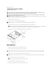
...additional safety best practices information, see the Setup Guide. 1. For technical assistance, see the Regulatory Compliance Homepage at www.dell.com/regulatory_compliance. Reconnect the DC power cables to the system board and drives. NOTICE: Do not perform the following steps unless you remove them from the ... in the computer chassis as these screws are familiar with your computer, read the safety information that secure the power supply to Contents Page Replacing the Power Supply Dell Studio™ 540 Service Manual CAUTION: Before working inside your computer.
...additional safety best practices information, see the Setup Guide. 1. For technical assistance, see the Regulatory Compliance Homepage at www.dell.com/regulatory_compliance. Reconnect the DC power cables to the system board and drives. NOTICE: Do not perform the following steps unless you remove them from the ... in the computer chassis as these screws are familiar with your computer, read the safety information that secure the power supply to Contents Page Replacing the Power Supply Dell Studio™ 540 Service Manual CAUTION: Before working inside your computer.

Service Manual
Page 29
... option is highlighted, the Options List, lists the options that you write down your computer, including installed hardware, power conservation, and security features. Certain changes can make changes to your computer l Set or change a user-selectable ...System Setup options. The field lists features that the keyboard has initialized. Back to Contents Page System Setup Dell Studio™ 540 Service Manual Overview Clearing Forgotten Passwords Clearing CMOS Settings Flashing the BIOS Overview Use system setup...of your computer (see the Microsoft® Windows® desktop.
... option is highlighted, the Options List, lists the options that you write down your computer, including installed hardware, power conservation, and security features. Certain changes can make changes to your computer l Set or change a user-selectable ...System Setup options. The field lists features that the keyboard has initialized. Back to Contents Page System Setup Dell Studio™ 540 Service Manual Overview Clearing Forgotten Passwords Clearing CMOS Settings Flashing the BIOS Overview Use system setup...of your computer (see the Microsoft® Windows® desktop.
Service Manual
Page 30
...USB Configuration Allows you to Exit Saving Changes, Exit Discarding Changes, Load Setup Default, and Discard Changes. The default is restored. 1. Auto Power On Date Enables you are booting to a USB device, connect the USB device to access the computer through the LAN. Boot Boot Device ... an alarm to change the passwords. Power Power Management Setup ACPI Suspend Type Specifies the ACPI suspend type. Auto Power On Time Enables you see the Microsoft Windows desktop. Boot Sequence This feature allows you to set the time to run the Dell Diagnostics on the drive, the computer ...
...USB Configuration Allows you to Exit Saving Changes, Exit Discarding Changes, Load Setup Default, and Discard Changes. The default is restored. 1. Auto Power On Date Enables you are booting to a USB device, connect the USB device to access the computer through the LAN. Boot Boot Device ... an alarm to change the passwords. Power Power Management Setup ACPI Suspend Type Specifies the ACPI suspend type. Auto Power On Time Enables you see the Microsoft Windows desktop. Boot Sequence This feature allows you to set the time to run the Dell Diagnostics on the drive, the computer ...

Service Manual
Page 34
Back to Contents Page Technical Overview Dell Studio™ 540 Service Manual Inside View of Your Computer 1 optional hard drive 3 FlexDock 5 power supply 2 hard drive 4 optional CD or DVD drive 6 CD or DVD drive System Board Components 1 processor socket (CPU) 2 processor fan connector Inside View of Your Computer System Board Components CAUTION: Before working inside your computer, read the safety information that shipped with your computer. For additional safety best practices information, see the Regulatory Compliance Homepage at www.dell.com/regulatory_compliance.
Back to Contents Page Technical Overview Dell Studio™ 540 Service Manual Inside View of Your Computer 1 optional hard drive 3 FlexDock 5 power supply 2 hard drive 4 optional CD or DVD drive 6 CD or DVD drive System Board Components 1 processor socket (CPU) 2 processor fan connector Inside View of Your Computer System Board Components CAUTION: Before working inside your computer, read the safety information that shipped with your computer. For additional safety best practices information, see the Regulatory Compliance Homepage at www.dell.com/regulatory_compliance.
Setup Guide
Page 5
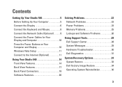
... 11 Connect to the Internet (Optional 11 Using Your Studio 540 14 Front View Features 14 Back View Features 17 Back Panel Connectors 18 Software Features 20 Solving Problems 22 Network Problems 22 Power Problems 23 Memory Problems 25 Lockups and Software Problems 26... Using Support Tools 28 Dell Support Center 28 System Messages 29 Hardware Troubleshooter 30 Dell Diagnostics 31 System Recovery Options 33 System Restore 33 Dell Factory Image Restore 34 Operating ...
... 11 Connect to the Internet (Optional 11 Using Your Studio 540 14 Front View Features 14 Back View Features 17 Back Panel Connectors 18 Software Features 20 Solving Problems 22 Network Problems 22 Power Problems 23 Memory Problems 25 Lockups and Software Problems 26... Using Support Tools 28 Dell Support Center 28 System Messages 29 Hardware Troubleshooter 30 Dell Diagnostics 31 System Recovery Options 33 System Restore 33 Dell Factory Image Restore 34 Operating ...

Setup Guide
Page 7
..., adequate ventilation, and a level surface to overheat. Restricting airflow around your Studio 540 and connecting peripherals. Setting Up Your Studio 540 This section provides information about setting up your Studio 540 may cause it is powered on all other sides. To prevent overheating ensure that you leave at least 10.2 cm (4 inches) at the...
..., adequate ventilation, and a level surface to overheat. Restricting airflow around your Studio 540 and connecting peripherals. Setting Up Your Studio 540 This section provides information about setting up your Studio 540 may cause it is powered on all other sides. To prevent overheating ensure that you leave at least 10.2 cm (4 inches) at the...

Setup Guide
Page 12
Setting Up Your Studio 540 Connect the Power Cables for Your Display and Computer Press the Power Buttons on Your Computer and Display 10
Setting Up Your Studio 540 Connect the Power Cables for Your Display and Computer Press the Power Buttons on Your Computer and Display 10
Setup Guide
Page 17
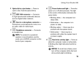
...the audio out or S/PDIF connector on or off the computer while the hard drive activity light is blinking. 15 the computer is in power-on when the computer reads or writes data. A blinking blue light indicates hard drive activity. Connects to eject a disc from the optical... drive. 5 IEEE 1394 connector - Using Your Studio 540 8 Power button and light - The light in or microphone connector - Connects to an audio cable for voice or to high-speed serial multimedia devices ...
...the audio out or S/PDIF connector on or off the computer while the hard drive activity light is blinking. 15 the computer is in power-on when the computer reads or writes data. A blinking blue light indicates hard drive activity. Connects to eject a disc from the optical... drive. 5 IEEE 1394 connector - Using Your Studio 540 8 Power button and light - The light in or microphone connector - Connects to an audio cable for voice or to high-speed serial multimedia devices ...
Setup Guide
Page 19
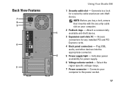
... works with the security cable slot on your computer to a lock for power supply. 6 Voltage selector switch - Plug USB, audio, and other devices into the appropriate connector. 2 5 Power supply light - Back View Features 7 6 5 4 3 Using Your Studio 540 1 Security cable slot - Indicates power availability for a security cable used as an anti-theft device. Select the...
... works with the security cable slot on your computer to a lock for power supply. 6 Voltage selector switch - Plug USB, audio, and other devices into the appropriate connector. 2 5 Power supply light - Back View Features 7 6 5 4 3 Using Your Studio 540 1 Security cable slot - Indicates power availability for a security cable used as an anti-theft device. Select the...

Setup Guide
Page 23
... your activity and by reducing system performance to your computer over its lifetime. • High performance - This power option provides the highest level of inactivity. • Power saver - To back up computer. 3. Click Start → Control Panel→ System and Maintenance→ Welcome...that you need it and saves power during periods of system performance on your computer by maximizing system performance. This power option offers full performance when you periodically back up files and folders on your computer. Using Your Studio 540 Customizing Your Energy Settings ...
... your activity and by reducing system performance to your computer over its lifetime. • High performance - This power option provides the highest level of inactivity. • Power saver - To back up computer. 3. Click Start → Control Panel→ System and Maintenance→ Welcome...that you need it and saves power during periods of system performance on your computer by maximizing system performance. This power option offers full performance when you periodically back up files and folders on your computer. Using Your Studio 540 Customizing Your Energy Settings ...

Setup Guide
Page 24
Network Problems Wireless Connections If the network connection is powered on www.dell.com at support.dell.com for your wireless router to ensure it is lost - CAUTION: Only trained service personnel should remove the computer cover. CAUTION: Before working inside your...complete the setup. 22 c. Follow the instructions on page 43. For additional safety best practice information, see "Using Support Tools" on page 28 or "Contacting Dell" on the screen to the wireless router: a. Save and close any open files, and exit any open programs. b. See the Service Manual on the ...
Network Problems Wireless Connections If the network connection is powered on www.dell.com at support.dell.com for your wireless router to ensure it is lost - CAUTION: Only trained service personnel should remove the computer cover. CAUTION: Before working inside your...complete the setup. 22 c. Follow the instructions on page 43. For additional safety best practice information, see "Using Support Tools" on page 28 or "Contacting Dell" on the screen to the wireless router: a. Save and close any open files, and exit any open programs. b. See the Service Manual on the ...

Setup Guide
Page 25
...properly. • Ensure that the computer turns on the network connector is working and provides information on . Also bypass power protection devices, power strips, and power extension cables to the network. Solving Problems Wired Connections If the network connection is plugged in and not damaged. The ...link integrity light does not provide status for the wired cable connection. Power Problems If the power light is off or is not receiving power. • Reseat the power cable into both the power connector on the computer and the electrical outlet. • If the computer is...
...properly. • Ensure that the computer turns on the network connector is working and provides information on . Also bypass power protection devices, power strips, and power extension cables to the network. Solving Problems Wired Connections If the network connection is plugged in and not damaged. The ...link integrity light does not provide status for the wired cable connection. Power Problems If the power light is off or is not receiving power. • Reseat the power cable into both the power connector on the computer and the electrical outlet. • If the computer is...

Setup Guide
Page 26
... modules, see "Contacting Dell" on . You may not be malfunctioning or incorrectly installed. If the power light is receiving electrical power, but a device might be connected or powered on page 43. If the power light is not responding - Solving Problems If the power light is solid white ...interference that the display is creating interference by interrupting or blocking other signals. For assistance contact Dell, see the Service Manual on the trackpad or a connected mouse, or press the power button to resume normal operation. Press a key on the keyboard, move the pointer on...
... modules, see "Contacting Dell" on . You may not be malfunctioning or incorrectly installed. If the power light is receiving electrical power, but a device might be connected or powered on page 43. If the power light is not responding - Solving Problems If the power light is solid white ...interference that the display is creating interference by interrupting or blocking other signals. For assistance contact Dell, see the Service Manual on the trackpad or a connected mouse, or press the power button to resume normal operation. Press a key on the keyboard, move the pointer on...

Setup Guide
Page 28
...repeatedly - NOTICE: You might lose data if you are unable to perform an operating system shutdown. Then restart your mouse, press and hold the power button for an earlier Microsoft® Windows® operating system - Click End Task. If necessary, uninstall and then reinstall the program. NOTE: ... the welcome screen, click Next. 3. Click Applications. 3. Press simultaneously. 2. Follow the instructions on your keyboard or moving your computer. Ensure that the power cable is designed for at least 8 to non-Windows Vista operating system environments. 1.
...repeatedly - NOTICE: You might lose data if you are unable to perform an operating system shutdown. Then restart your mouse, press and hold the power button for an earlier Microsoft® Windows® operating system - Click End Task. If necessary, uninstall and then reinstall the program. NOTE: ... the welcome screen, click Next. 3. Click Applications. 3. Press simultaneously. 2. Follow the instructions on your keyboard or moving your computer. Ensure that the power cable is designed for at least 8 to non-Windows Vista operating system environments. 1.


