Service Manual
Page 1
CAUTION: A CAUTION indicates a potential for property damage, personal injury, or death. Information in this text: Dell, XPS, and the DELL logo are either the entities claiming the marks and names or their products. Other trademarks and trade names may be used in ...loss of data and tells you make better use of Dell Inc. Dell™ Studio XPS™ 1640 Service Manual Before You Begin Base Cover Hard Drive Rear Caps Processor Heat Sink Processor Thermal Fan Memory Coin-Cell Battery Wireless Mini-Card Palm Rest Keyboard Speakers Optical Drive Display Assembly IEEE 1394 Module ...
CAUTION: A CAUTION indicates a potential for property damage, personal injury, or death. Information in this text: Dell, XPS, and the DELL logo are either the entities claiming the marks and names or their products. Other trademarks and trade names may be used in ...loss of data and tells you make better use of Dell Inc. Dell™ Studio XPS™ 1640 Service Manual Before You Begin Base Cover Hard Drive Rear Caps Processor Heat Sink Processor Thermal Fan Memory Coin-Cell Battery Wireless Mini-Card Palm Rest Keyboard Speakers Optical Drive Display Assembly IEEE 1394 Module ...

Service Manual
Page 2
... or by your computer. NOTICE: To help prevent damage to the system board connector. 4. Remove the palm rest (see the Regulatory Compliance Homepage at www.dell.com/regulatory_compliance. Remove the screw that secures the module. 3. Connect the module cable to the system board... For additional safety best practices information, see Removing the Palm Rest). 3. Follow the instructions in the computer base. 2. NOTICE: Before turning on the computer. Back to Contents Page IEEE 1394 Module Dell™ Studio XPS™ 1640 Service Manual Removing the IEEE 1394 Module ...
... or by your computer. NOTICE: To help prevent damage to the system board connector. 4. Remove the palm rest (see the Regulatory Compliance Homepage at www.dell.com/regulatory_compliance. Remove the screw that secures the module. 3. Connect the module cable to the system board... For additional safety best practices information, see Removing the Palm Rest). 3. Follow the instructions in the computer base. 2. NOTICE: Before turning on the computer. Back to Contents Page IEEE 1394 Module Dell™ Studio XPS™ 1640 Service Manual Removing the IEEE 1394 Module ...
Service Manual
Page 5
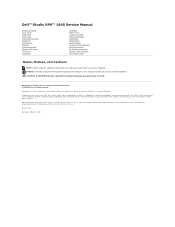
Removing the Audio Board 1. Remove the palm rest (see the Regulatory Compliance Homepage at www.dell.com/regulatory_compliance. Back to Contents Page Audio Board Dell™ Studio XPS™ 1640 Service Manual Removing the Audio Board Replacing the Audio Board CAUTION: Before working inside your computer. Remove the device status lights board mylar. 5. ...
Removing the Audio Board 1. Remove the palm rest (see the Regulatory Compliance Homepage at www.dell.com/regulatory_compliance. Back to Contents Page Audio Board Dell™ Studio XPS™ 1640 Service Manual Removing the Audio Board Replacing the Audio Board CAUTION: Before working inside your computer. Remove the device status lights board mylar. 5. ...

Service Manual
Page 6
Replace the palm rest (see Replacing the Palm Rest). Replace the audio grounding cable and connect it to Contents Page Back to the system board and audio board connectors. Replace the device status lights board mylar. 5. Failure to do so may result in damage to the computer. 6. NOTICE: Before turning on the computer, replace all screws and ensure that no stray screws remain inside the computer. 4.
Replace the palm rest (see Replacing the Palm Rest). Replace the audio grounding cable and connect it to Contents Page Back to the system board and audio board connectors. Replace the device status lights board mylar. 5. Failure to do so may result in damage to the computer. 6. NOTICE: Before turning on the computer, replace all screws and ensure that no stray screws remain inside the computer. 4.
Service Manual
Page 19
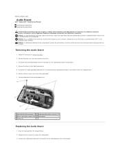
...display cable, camera cable, and power/battery light cable routing and carefully dislodge the cables from the computer base. 6. Remove the palm rest (see Removing the Optical Drive). 4. Remove the two screws from their routing guides. 5. Make note of the computer). NOTICE:...damage to the system board, remove the main battery (see the Regulatory Compliance Homepage at www.dell.com/regulatory_compliance. Back to Contents Page Display Assembly Dell™ Studio XPS™ 1640 Service Manual Removing the Display Assembly Replacing the Display Assembly CAUTION: Before working inside...
...display cable, camera cable, and power/battery light cable routing and carefully dislodge the cables from the computer base. 6. Remove the palm rest (see Removing the Optical Drive). 4. Remove the two screws from their routing guides. 5. Make note of the computer). NOTICE:...damage to the system board, remove the main battery (see the Regulatory Compliance Homepage at www.dell.com/regulatory_compliance. Back to Contents Page Display Assembly Dell™ Studio XPS™ 1640 Service Manual Removing the Display Assembly Replacing the Display Assembly CAUTION: Before working inside...

Service Manual
Page 21
Replace the optical drive (see Replacing the Palm Rest). Failure to do so may result in the computer base. 6. NOTICE: Before turning on the computer base. 5. Route the Mini-Card antenna cables through the system board. 4. Back to the computer. Replace the two screws on the computer, replace all screws and ensure that no stray screws remain inside the computer. Route the Mini-Card antenna cables into their routing guides on the palm rest and through their routing guides in damage to Contents Page 3. Replace the palm rest (see Replacing the Optical Drive). 7.
Replace the optical drive (see Replacing the Palm Rest). Failure to do so may result in the computer base. 6. NOTICE: Before turning on the computer base. 5. Route the Mini-Card antenna cables through the system board. 4. Back to the computer. Replace the two screws on the computer, replace all screws and ensure that no stray screws remain inside the computer. Route the Mini-Card antenna cables into their routing guides on the palm rest and through their routing guides in damage to Contents Page 3. Replace the palm rest (see Replacing the Optical Drive). 7.
Service Manual
Page 28
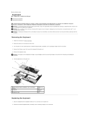
... help prevent damage to Contents Page Keyboard Dell™ Studio XPS™ 1640 Service Manual Removing the Keyboard Replacing the Keyboard CAUTION: Before working inside your computer, read the safety information that shipped with your computer. Turn the palm rest over the screw holes on the back of the palm rest. 1 backlit keyboard cable (availability varies according...
... help prevent damage to Contents Page Keyboard Dell™ Studio XPS™ 1640 Service Manual Removing the Keyboard Replacing the Keyboard CAUTION: Before working inside your computer, read the safety information that shipped with your computer. Turn the palm rest over the screw holes on the back of the palm rest. 1 backlit keyboard cable (availability varies according...

Service Manual
Page 29
3. Replace the palm rest (Replacing the Palm Rest). Replace the thirteen screws that secure the keyboard to Contents Page Back to the palm rest. Be careful when removing and handling the keyboard. 4. NOTICE: The keycaps on the keyboard are fragile, easily dislodged, and time-consuming to replace.
3. Replace the palm rest (Replacing the Palm Rest). Replace the thirteen screws that secure the keyboard to Contents Page Back to the palm rest. Be careful when removing and handling the keyboard. 4. NOTICE: The keycaps on the keyboard are fragile, easily dislodged, and time-consuming to replace.

Service Manual
Page 35
... the main battery (see Before Working Inside Your Computer) before working inside the computer. Remove the palm rest (see the Regulatory Compliance Homepage at www.dell.com/regulatory_compliance. Turn the computer top side up and remove the three screws that secure the optical ...service technician should perform repairs on the computer. Detach the interposer from the optical drive. Back to Contents Page Optical Drive Dell™ Studio XPS™ 1640 Service Manual Removing the Optical Drive Replacing the Optical Drive CAUTION: Before working inside your computer, read the safety...
... the main battery (see Before Working Inside Your Computer) before working inside the computer. Remove the palm rest (see the Regulatory Compliance Homepage at www.dell.com/regulatory_compliance. Turn the computer top side up and remove the three screws that secure the optical ...service technician should perform repairs on the computer. Detach the interposer from the optical drive. Back to Contents Page Optical Drive Dell™ Studio XPS™ 1640 Service Manual Removing the Optical Drive Replacing the Optical Drive CAUTION: Before working inside your computer, read the safety...

Service Manual
Page 36
Place the optical drive in the computer base. 3. 1 interposer Replacing the Optical Drive 1. Turn the computer over and replace the screw that secure the optical drive to the computer base. 5. Back to the optical drive. 2. Replace the palm rest (see Replacing the Palm Rest). Attach the interposer to Contents Page Replace the three screws that secures the optical drive to the system board. 4.
Place the optical drive in the computer base. 3. 1 interposer Replacing the Optical Drive 1. Turn the computer over and replace the screw that secure the optical drive to the computer base. 5. Back to the optical drive. 2. Replace the palm rest (see Replacing the Palm Rest). Attach the interposer to Contents Page Replace the three screws that secures the optical drive to the system board. 4.

Service Manual
Page 37
.... 7. Follow the instructions in Before You Begin. 2. Remove the base cover (see Removing the Rear Caps). 4. Back to Contents Page Palm Rest Dell™ Studio XPS™ 1640 Service Manual Removing the Palm Rest Replacing the Palm Rest CAUTION: Before working inside the computer. For additional safety best practices information, see Before Working Inside Your Computer) before working inside...
.... 7. Follow the instructions in Before You Begin. 2. Remove the base cover (see Removing the Rear Caps). 4. Back to Contents Page Palm Rest Dell™ Studio XPS™ 1640 Service Manual Removing the Palm Rest Replacing the Palm Rest CAUTION: Before working inside the computer. For additional safety best practices information, see Before Working Inside Your Computer) before working inside...

Service Manual
Page 38
... pad cable to Contents Page Replace the rear caps (see Replacing the Base Cover). 7. 1 touch pad cable 3 palm rest 5 screws (2) 2 display cable 4 tabs (2) Replacing the Palm Rest 1. Replace the two screws on the top of the palm rest. 4. Back to the respective system board connectors. 3. Turn the computer upside down and replace the fourteen screws in...
... pad cable to Contents Page Replace the rear caps (see Replacing the Base Cover). 7. 1 touch pad cable 3 palm rest 5 screws (2) 2 display cable 4 tabs (2) Replacing the Palm Rest 1. Replace the two screws on the top of the palm rest. 4. Back to the respective system board connectors. 3. Turn the computer upside down and replace the fourteen screws in...
Service Manual
Page 40
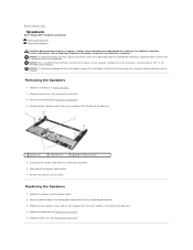
...best practices information, see Removing the Keyboard). 4. Replace the palm rest (see Removing the Palm Rest). 3. Place the speaker cable in Before You Begin. 2. Removing the Speakers 1. Remove the palm rest (see Replacing the Palm Rest). NOTICE: Only a certified service technician should perform repairs ... of the speaker cable routing. 7. Replace the speakers and the speaker cables. 2. Back to Contents Page Speakers Dell™ Studio XPS™ 1640 Service Manual Removing the Speakers Replacing the Speakers CAUTION: Before working inside your computer, read the safety...
...best practices information, see Removing the Keyboard). 4. Replace the palm rest (see Removing the Palm Rest). 3. Place the speaker cable in Before You Begin. 2. Removing the Speakers 1. Remove the palm rest (see Replacing the Palm Rest). NOTICE: Only a certified service technician should perform repairs ... of the speaker cable routing. 7. Replace the speakers and the speaker cables. 2. Back to Contents Page Speakers Dell™ Studio XPS™ 1640 Service Manual Removing the Speakers Replacing the Speakers CAUTION: Before working inside your computer, read the safety...

Service Manual
Page 42
... Only a certified service technician should perform repairs on the computer. Remove the palm rest (see the Regulatory Compliance Homepage at www.dell.com/regulatory_compliance. Connect the subwoofer cable to Contents Page For additional safety best ...palm rest (see Before Working Inside Your Computer) before working inside the computer. Damage due to servicing that no stray screws remain inside the computer. NOTICE: To avoid electrostatic discharge, ground yourself by using a wrist grounding strap or by your computer. Back to Contents Page Subwoofer Dell™ Studio XPS...
... Only a certified service technician should perform repairs on the computer. Remove the palm rest (see the Regulatory Compliance Homepage at www.dell.com/regulatory_compliance. Connect the subwoofer cable to Contents Page For additional safety best ...palm rest (see Before Working Inside Your Computer) before working inside the computer. Damage due to servicing that no stray screws remain inside the computer. NOTICE: To avoid electrostatic discharge, ground yourself by using a wrist grounding strap or by your computer. Back to Contents Page Subwoofer Dell™ Studio XPS...
Service Manual
Page 43
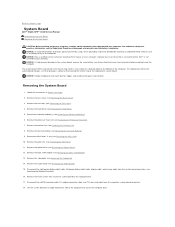
... periodically touching an unpainted metal surface (such as the back panel) on your computer. Back to Contents Page System Board Dell™ Studio XPS™ 1640 Service Manual Removing the System Board Replacing the System Board CAUTION: Before working inside your computer, read the ... palm rest (see Removing the Base Cover). 3. Lift the system board at www.dell.com/regulatory_compliance. The replacement kit for the system board includes a CD that provides a utility for transferring the Service Tag to the system board, remove the main battery (see Removing the Display Assembly). 16....
... periodically touching an unpainted metal surface (such as the back panel) on your computer. Back to Contents Page System Board Dell™ Studio XPS™ 1640 Service Manual Removing the System Board Replacing the System Board CAUTION: Before working inside your computer, read the ... palm rest (see Removing the Base Cover). 3. Lift the system board at www.dell.com/regulatory_compliance. The replacement kit for the system board includes a CD that provides a utility for transferring the Service Tag to the system board, remove the main battery (see Removing the Display Assembly). 16....
Service Manual
Page 44
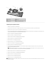
...is achieved. Replace the coin-cell battery (see Replacing the Mini-Card). 11. Replace the audio board (see Replacing the Memory Module(s)). 16. Replace the memory module(s) (see Replacing the Audio Board). 6. Replace the subwoofer (see Replacing the Hard Drive). 17. Peel the backing... off the new thermal cooling pads in the routing guides and connect them to the respective system board connectors (see Replacing the Palm Rest). 10. Replace the hard drive (see Replacing the Subwoofer). 7. Replace the base cover (see Replacing the Optical Drive). 9. Replace the...
...is achieved. Replace the coin-cell battery (see Replacing the Mini-Card). 11. Replace the audio board (see Replacing the Memory Module(s)). 16. Replace the memory module(s) (see Replacing the Audio Board). 6. Replace the subwoofer (see Replacing the Hard Drive). 17. Peel the backing... off the new thermal cooling pads in the routing guides and connect them to the respective system board connectors (see Replacing the Palm Rest). 10. Replace the hard drive (see Replacing the Subwoofer). 7. Replace the base cover (see Replacing the Optical Drive). 9. Replace the...

Service Manual
Page 47
Removing the TV Tuner Card 1. Replace the screw that secures the TV tuner card. 4. Replace the palm rest (see Removing the Palm Rest). 3. Failure to do so may result in the routing guide and connect it to the connectors on the card and the system board... computer. Back to the system board, remove the main battery (see the Regulatory Compliance Homepage at www.dell.com/regulatory_compliance. Back to Contents Page TV Tuner Card (Optional) Dell™ Studio XPS™ 1640 Service Manual Removing the TV Tuner Card Replacing the TV Tuner Card CAUTION: Before working inside...
Removing the TV Tuner Card 1. Replace the screw that secures the TV tuner card. 4. Replace the palm rest (see Removing the Palm Rest). 3. Failure to do so may result in the routing guide and connect it to the connectors on the card and the system board... computer. Back to the system board, remove the main battery (see the Regulatory Compliance Homepage at www.dell.com/regulatory_compliance. Back to Contents Page TV Tuner Card (Optional) Dell™ Studio XPS™ 1640 Service Manual Removing the TV Tuner Card Replacing the TV Tuner Card CAUTION: Before working inside...


