
Monitor Users Guide
Page 3
Contents About Your Monitor 5 Package Contents 5 Product Features 6 Identifying Parts and Controls 7 Monitor Specifications 11 Plug and Play Capability 17 Universal Serial Bus (USB) Interface 18 LCD Monitor Quality and Pixel Policy 20 Maintenance Guidelines 20 Setting Up the Monitor 21 Attaching the Stand 21 Connecting Your Monitor 23 Organizing Your Cables 24 Removing the Monitor Stand 25 Wall Mounting (Optional 26 Operating the Monitor 27 Power On the Monitor 27 Using the Front-Panel Controls 27 Contents | 3
Contents About Your Monitor 5 Package Contents 5 Product Features 6 Identifying Parts and Controls 7 Monitor Specifications 11 Plug and Play Capability 17 Universal Serial Bus (USB) Interface 18 LCD Monitor Quality and Pixel Policy 20 Maintenance Guidelines 20 Setting Up the Monitor 21 Attaching the Stand 21 Connecting Your Monitor 23 Organizing Your Cables 24 Removing the Monitor Stand 25 Wall Mounting (Optional 26 Operating the Monitor 27 Power On the Monitor 27 Using the Front-Panel Controls 27 Contents | 3
Monitor Users Guide
Page 4
Using the On-Screen Display (OSD) Menu 29 Setting the Maximum Resolution 35 Using the Tilt, Swivel, and Vertical Extension 36 Rotating the Monitor 37 Adjusting the Rotation Display Settings of Your System 38 Troubleshooting 39 Self-Test 39 Built-in Diagnostics 40 Common Problems 41 Product Specific Problems 43 Universal Serial Bus (USB) Specific Problems 44 Appendix 45 FCC Notices (U.S. Only) and Other Regulatory Information 45 Contact Dell 45 4 | Contents
Using the On-Screen Display (OSD) Menu 29 Setting the Maximum Resolution 35 Using the Tilt, Swivel, and Vertical Extension 36 Rotating the Monitor 37 Adjusting the Rotation Display Settings of Your System 38 Troubleshooting 39 Self-Test 39 Built-in Diagnostics 40 Common Problems 41 Product Specific Problems 43 Universal Serial Bus (USB) Specific Problems 44 Appendix 45 FCC Notices (U.S. Only) and Other Regulatory Information 45 Contact Dell 45 4 | Contents

Monitor Users Guide
Page 5
NOTE: To set up with your monitor. Ensure that you have received all the components and Contact Dell if something is missing. NOTE: Some items may not ship with any other stand, please refer to the respective stand setup guide for setup instructions. Some features or media may not be optional and may be available in certain countries. About Your Monitor Package Contents Your monitor ships with the components shown below. Monitor Stand Riser Stand Base About Your Monitor | 5
NOTE: To set up with your monitor. Ensure that you have received all the components and Contact Dell if something is missing. NOTE: Some items may not ship with any other stand, please refer to the respective stand setup guide for setup instructions. Some features or media may not be optional and may be available in certain countries. About Your Monitor Package Contents Your monitor ships with the components shown below. Monitor Stand Riser Stand Base About Your Monitor | 5
Monitor Users Guide
Page 6
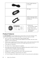
...Hz (165Hz with overclock) and a rapid response time of 1 ms. • Color gamut of set-up and screen optimization. 6 | About Your Monitor Power Cable (Varies by your system. • On-Screen Display (OSD) adjustments for ease of 72% NTSC. • Tilt, Swivel, Pivot, ... Countries) DP Cable USB 3.0 Upstream Cable (Enables the USB Ports on the Monitor) • Drivers and Documentation Media • Quick Setup Guide • Safety, Environmental, and Regulatory Information Product Features The Dell S2417DG flat panel display has an active matrix, Thin-Film Transistor (TFT), Liquid Crystal...
...Hz (165Hz with overclock) and a rapid response time of 1 ms. • Color gamut of set-up and screen optimization. 6 | About Your Monitor Power Cable (Varies by your system. • On-Screen Display (OSD) adjustments for ease of 72% NTSC. • Tilt, Swivel, Pivot, ... Countries) DP Cable USB 3.0 Upstream Cable (Enables the USB Ports on the Monitor) • Drivers and Documentation Media • Quick Setup Guide • Safety, Environmental, and Regulatory Information Product Features The Dell S2417DG flat panel display has an active matrix, Thin-Film Transistor (TFT), Liquid Crystal...

Monitor Users Guide
Page 7
... Parts and Controls Front View Label Description 1 Function buttons (For more information, see Operating the Monitor) 2 Power On/Off button (with LED indicator) NOTE: For displays with glossy bezels the user should consider the placement of the display as the bezel ... and Mercury-Free for the panel only. • 0.5 W standby power when in sleep mode. • Energy Gauge shows the energy level being consumed by the monitor in real time. • Analog backlight dimming control for flicker-free display.
... Parts and Controls Front View Label Description 1 Function buttons (For more information, see Operating the Monitor) 2 Power On/Off button (with LED indicator) NOTE: For displays with glossy bezels the user should consider the placement of the display as the bezel ... and Mercury-Free for the panel only. • 0.5 W standby power when in sleep mode. • Energy Gauge shows the energy level being consumed by the monitor in real time. • Analog backlight dimming control for flicker-free display.

Monitor Users Guide
Page 8
Refer to this label if you need to organize cables by placing them through the slot. 8 | About Your Monitor Secures monitor with monitor stand Label Description 1 VESA mounting holes (100 mm x 100 mm behind attached VESA Cover) 2 Regulatory label 3 Stand release button 4 ...Security lock slot 5 Barcode serial number label 6 Cable-management slot Use Wall mount monitor using VESA-compatible wall mount kit (100 mm x 100 mm). Lists the regulatory approvals. Back View Back view with security lock (security lock ...
Refer to this label if you need to organize cables by placing them through the slot. 8 | About Your Monitor Secures monitor with monitor stand Label Description 1 VESA mounting holes (100 mm x 100 mm behind attached VESA Cover) 2 Regulatory label 3 Stand release button 4 ...Security lock slot 5 Barcode serial number label 6 Cable-management slot Use Wall mount monitor using VESA-compatible wall mount kit (100 mm x 100 mm). Lists the regulatory approvals. Back View Back view with security lock (security lock ...

Monitor Users Guide
Page 9
Connect your USB device. Connect the headphones. About Your Monitor | 9 Side View Label Description 1 USB 3.0 port 2 USB 3.0 port with your monitor) from the USBupstream port on the monitor to your computer. NOTE: To use this port, you must connect the USB cable (shipped with PowerShare 3 Headphone-out jack Use Connect your USB device (also supports fast charging).
Connect your USB device. Connect the headphones. About Your Monitor | 9 Side View Label Description 1 USB 3.0 port 2 USB 3.0 port with your monitor) from the USBupstream port on the monitor to your computer. NOTE: To use this port, you must connect the USB cable (shipped with PowerShare 3 Headphone-out jack Use Connect your USB device (also supports fast charging).

Monitor Users Guide
Page 10
.... NOTE: To use this port and your computer to enable the USB ports on the monitor to your computer using a M3 x 6 mm screw (screw not included). Bottom View Bottom view without monitor stand Label Description 1 Power cable connector 2 Stand lock feature 3 Line-out port 4... DisplayPort 5 HDMI port 6 USB upstream port 7 USB 3.0 ports (2) Use Connect the power cable (shipped with your monitor). Connect to your computer. 10 | About Your Monitor Connect to the monitor using the DP cable (shipped with your monitor). NOTE: This port does not support headphones.
.... NOTE: To use this port and your computer to enable the USB ports on the monitor to your computer using a M3 x 6 mm screw (screw not included). Bottom View Bottom view without monitor stand Label Description 1 Power cable connector 2 Stand lock feature 3 Line-out port 4... DisplayPort 5 HDMI port 6 USB upstream port 7 USB 3.0 ports (2) Use Connect the power cable (shipped with your monitor). Connect to your computer. 10 | About Your Monitor Connect to the monitor using the DP cable (shipped with your monitor). NOTE: This port does not support headphones.

Monitor Users Guide
Page 11
...8226; 1 x Headphone-out jack - Side • 1 x Audio line-out jack - Side • 2 x USB 3.0 port - Bottom About Your Monitor | 11 TFT LCD TN 16:9 604.7 mm (23.8 inches) 526.85 mm (20.74 inches) 296.35 mm (11.67 inches) 156131.99 mm2... • 4 x USB 3.0 downstream ports (including 1 port which supports power-charging) • 1 x DP 1.2 • 1 x HDMI 1.4 • 1 x USB 3.0 upstream port - Monitor Specifications Flat Panel Specifications Model Screen type Panel technology Aspect ratio Viewable image Diagonal Horizontal, Active Area Vertical, Active Area Area Pixel pitch Pixel per...
...8226; 1 x Headphone-out jack - Side • 1 x Audio line-out jack - Side • 2 x USB 3.0 port - Bottom About Your Monitor | 11 TFT LCD TN 16:9 604.7 mm (23.8 inches) 526.85 mm (20.74 inches) 296.35 mm (11.67 inches) 156131.99 mm2... • 4 x USB 3.0 downstream ports (including 1 port which supports power-charging) • 1 x DP 1.2 • 1 x HDMI 1.4 • 1 x USB 3.0 upstream port - Monitor Specifications Flat Panel Specifications Model Screen type Panel technology Aspect ratio Viewable image Diagonal Horizontal, Active Area Vertical, Active Area Area Pixel pitch Pixel per...
Monitor Users Guide
Page 12
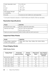
Resolution Specifications Model S2417DG Horizontal scan range 30 kHz to 160 kHz (automatic) Vertical scan range 30 Hz to 90° No Security lock slot (cable lock sold separately) * Color gamut (typical) is based on CIE1976 (82%) and CIE1931 (72%) test standards. Height adjustable stand Tilt Swivel Pivot Dell Display Manager Compatibility Security... (Hz) 60 60 50 60 60 50 Pixel Clock (MHz) 25.2 26.25 26 40 65 74.25 Sync Polarity (Horizontal/ Vertical) 12 | About Your Monitor
Resolution Specifications Model S2417DG Horizontal scan range 30 kHz to 160 kHz (automatic) Vertical scan range 30 Hz to 90° No Security lock slot (cable lock sold separately) * Color gamut (typical) is based on CIE1976 (82%) and CIE1931 (72%) test standards. Height adjustable stand Tilt Swivel Pivot Dell Display Manager Compatibility Security... (Hz) 60 60 50 60 60 50 Pixel Clock (MHz) 25.2 26.25 26 40 65 74.25 Sync Polarity (Horizontal/ Vertical) 12 | About Your Monitor
Monitor Users Guide
Page 13
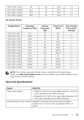
...1440p 45 55.6 67.5 88.8 DP Display Modes 60 74.25 +/+ 50 141.5 -/+ 60 148.5 +/+ 60 241.5 +/- Electrical Specifications Model S2417DG Video input signals • HDMI 1.4, 600 mV for each differential line, 100 ohm input impedance per differential pair • DisplayPort 1.2, 600 mV ... pair Synchronization input signals Separate horizontal and vertical synchronization, polarity-free TTL level, SOG (Composite SYNC on green) About Your Monitor | 13 Please visit http://www.geforce.com to know whether your NVIDIA graphics card supports the G-SYNC feature. Display Mode ...
...1440p 45 55.6 67.5 88.8 DP Display Modes 60 74.25 +/+ 50 141.5 -/+ 60 148.5 +/+ 60 241.5 +/- Electrical Specifications Model S2417DG Video input signals • HDMI 1.4, 600 mV for each differential line, 100 ohm input impedance per differential pair • DisplayPort 1.2, 600 mV ... pair Synchronization input signals Separate horizontal and vertical synchronization, polarity-free TTL level, SOG (Composite SYNC on green) About Your Monitor | 13 Please visit http://www.geforce.com to know whether your NVIDIA graphics card supports the G-SYNC feature. Display Mode ...
Monitor Users Guide
Page 14
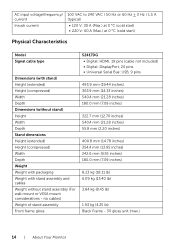
no cables) Weight of stand assembly Front frame gloss S2417DG • Digital: HDMI, 19 pins (cable not included) • Digital: DisplayPort, 20 pins • Universal Serial Bus: USB, 9 pins 493.9 mm (19.44 inches) 363.9 ... (18.11 lb) 6.09 kg (13.40 lb) 3.84 kg (8.45 lb) 1.93 kg (4.25 lb) Black Frame - 30 gloss unit (max.) 14 | About Your Monitor AC input voltage/frequency/ current Inrush current 100 VAC to 240 VAC / 50 Hz or 60 Hz + 3 Hz / 1.5 A (typical) • 120 V: 30 A (Max.) at 0 °...
no cables) Weight of stand assembly Front frame gloss S2417DG • Digital: HDMI, 19 pins (cable not included) • Digital: DisplayPort, 20 pins • Universal Serial Bus: USB, 9 pins 493.9 mm (19.44 inches) 363.9 ... (18.11 lb) 6.09 kg (13.40 lb) 3.84 kg (8.45 lb) 1.93 kg (4.25 lb) Black Frame - 30 gloss unit (max.) 14 | About Your Monitor AC input voltage/frequency/ current Inrush current 100 VAC to 240 VAC / 50 Hz or 60 Hz + 3 Hz / 1.5 A (typical) • 120 V: 30 A (Max.) at 0 °...

Monitor Users Guide
Page 15
... Consumption Normal operation Active Active Active White 73 W (maximum)** 33 W (typical) Active-off - - - Environmental Characteristics Model S2417DG Compliant Standards • RoHS-compliant • Arsenic-Free glass and Mercury-Free for the panel only Temperature Operating 0 °C ...) • Shipping: 5% to as Power Save Mode*. If the computer detects input from the monitor. ** Maximum power consumption with max luminance, and USB active. About Your Monitor | 15 Off Less than 0.5 W Switch off mode Inactive Inactive Blanked White (blinking) Less than...
... Consumption Normal operation Active Active Active White 73 W (maximum)** 33 W (typical) Active-off - - - Environmental Characteristics Model S2417DG Compliant Standards • RoHS-compliant • Arsenic-Free glass and Mercury-Free for the panel only Temperature Operating 0 °C ...) • Shipping: 5% to as Power Save Mode*. If the computer detects input from the monitor. ** Maximum power consumption with max luminance, and USB active. About Your Monitor | 15 Off Less than 0.5 W Switch off mode Inactive Inactive Blanked White (blinking) Less than...

Monitor Users Guide
Page 16
Pin Assignments DisplayPort Connector Pin 20-pin Side of the Number Connected Signal Cable 1 ML0(p) 2 GND 3 ML0(n) 4 ML1(p) 5 GND 6 ML1(n) 7 ML2(p) 8 GND 9 ML2(n) 10 ML3(p) 11 GND 12 ML3(n) 13 GND 14 GND 15 AUX(p) 16 GND 17 AUX(n) 18 GND 19 Re-PWR 20 +3.3 V DP_PWR 16 | About Your Monitor
Pin Assignments DisplayPort Connector Pin 20-pin Side of the Number Connected Signal Cable 1 ML0(p) 2 GND 3 ML0(n) 4 ML1(p) 5 GND 6 ML1(n) 7 ML2(p) 8 GND 9 ML2(n) 10 ML3(p) 11 GND 12 ML3(n) 13 GND 14 GND 15 AUX(p) 16 GND 17 AUX(n) 18 GND 19 Re-PWR 20 +3.3 V DP_PWR 16 | About Your Monitor

Monitor Users Guide
Page 17
... (DDC) protocols so that the system can select different settings if desired. Most monitor installations are automatic; For more information about changing the monitor settings, see Operating the Monitor. About Your Monitor | 17 you can configure itself and optimize the monitor settings. HDMI Connector Pin 19-pin Side of the Number Connected Signal Cable 1 TMDS... CLOCK (SCL) 16 DDC DATA (SDA) 17 DDC/CEC Ground 18 +5V POWER 19 HOT PLUG DETECT Plug and Play Capability You can install the monitor in any Plug and Play-compatible system.
... (DDC) protocols so that the system can select different settings if desired. Most monitor installations are automatic; For more information about changing the monitor settings, see Operating the Monitor. About Your Monitor | 17 you can configure itself and optimize the monitor settings. HDMI Connector Pin 19-pin Side of the Number Connected Signal Cable 1 TMDS... CLOCK (SCL) 16 DDC DATA (SDA) 17 DDC/CEC Ground 18 +5V POWER 19 HOT PLUG DETECT Plug and Play Capability You can install the monitor in any Plug and Play-compatible system.

Monitor Users Guide
Page 18
...(Max, each port) 4.5 W (Max, each port) * Up to 2 A on the monitor. USB Upstream Connector Pin Number 1 2 3 4 5 6 7 8 9 9-pin Side of the Connector VCC DD+ GND SSTXSSTX+ GND SSRXSSRX+ 18 | About Your Monitor Universal Serial Bus (USB) Interface This section gives you information about the USB ports that are... available on USB downstream port (port with BC1.2- NOTE: This monitor is Super-Speed USB 3.0 compatible. lightning icon...
...(Max, each port) 4.5 W (Max, each port) * Up to 2 A on the monitor. USB Upstream Connector Pin Number 1 2 3 4 5 6 7 8 9 9-pin Side of the Connector VCC DD+ GND SSTXSSTX+ GND SSRXSSRX+ 18 | About Your Monitor Universal Serial Bus (USB) Interface This section gives you information about the USB ports that are... available on USB downstream port (port with BC1.2- NOTE: This monitor is Super-Speed USB 3.0 compatible. lightning icon...

Monitor Users Guide
Page 19
bottom • 2 downstream - the port with lightning icon; side • Power Charging Port- NOTE: The monitor's USB interface works only when the monitor is BC1.2 compatible. bottom • 2 downstream - supports fast current charging capability if the device is On or ...in the power save mode. NOTE: USB 3.0 functionality requires a USB 3.0-capable computer. About Your Monitor | 19 USB Downstream Connector Pin Number 1 2 3 4 5 6 7 8 9 9-pin Side of the Connector VCC DD+ GND SSRXSSRX+ GND SSTXSSTX+ USB ...
bottom • 2 downstream - the port with lightning icon; side • Power Charging Port- NOTE: The monitor's USB interface works only when the monitor is BC1.2 compatible. bottom • 2 downstream - supports fast current charging capability if the device is On or ...in the power save mode. NOTE: USB 3.0 functionality requires a USB 3.0-capable computer. About Your Monitor | 19 USB Downstream Connector Pin Number 1 2 3 4 5 6 7 8 9 9-pin Side of the Connector VCC DD+ GND SSRXSSRX+ GND SSTXSSTX+ USB ...

Monitor Users Guide
Page 20
... . 20 | About Your Monitor LCD Monitor Quality and Pixel Policy During the LCD Monitor manufacturing process, it off with a cloth. • Handle your monitor with care as a darker-colored monitor may get scratched and show white scuff marks more than a lighter-colored monitor. • To help maintain the best image quality on Dell Monitor Quality and Pixel Policy...
... . 20 | About Your Monitor LCD Monitor Quality and Pixel Policy During the LCD Monitor manufacturing process, it off with a cloth. • Handle your monitor with care as a darker-colored monitor may get scratched and show white scuff marks more than a lighter-colored monitor. • To help maintain the best image quality on Dell Monitor Quality and Pixel Policy...

Monitor Users Guide
Page 21
... applicable for the set up instructions. Then, align the stand base protruded blocks to the respective stand setup guide for a monitor with the triangle mark, , facing upward. NOTE: This is shipped from the factory. When any other stand is bought, please refer to the matching slot ...on the back of the monitor. 3 Press the stand till it . 2 Insert the two tabs on the upper part of the stand to the groove on the stand.
... applicable for the set up instructions. Then, align the stand base protruded blocks to the respective stand setup guide for a monitor with the triangle mark, , facing upward. NOTE: This is shipped from the factory. When any other stand is bought, please refer to the matching slot ...on the back of the monitor. 3 Press the stand till it . 2 Insert the two tabs on the upper part of the stand to the groove on the stand.

Monitor Users Guide
Page 22
5 Insert the stand base blocks fully into the stand slot. 6 Lift the screw handle and turn the screw clockwise. 7 After fully tightening the screw, fold the screw handle flat within the recess. 22 | Setting Up the Monitor
5 Insert the stand base blocks fully into the stand slot. 6 Lift the screw handle and turn the screw clockwise. 7 After fully tightening the screw, fold the screw handle flat within the recess. 22 | Setting Up the Monitor


