
Dell Precision Tower 7810 Owners Manual
Page 3
... the HDD Thermal Sensor...21 Removing the Input/Output (I/O) Panel 21 Installing the Input/Output (I/O) Panel 23 Removing the Memory Shroud...23 Installing the Memory Shroud...24 Removing the Memory...24 Installing the Memory...25 Removing the Coin-Cell Battery...25 Installing the Coin-Cell Battery...25 Removing the Heatsink Assembly...25 Installing the...
... the HDD Thermal Sensor...21 Removing the Input/Output (I/O) Panel 21 Installing the Input/Output (I/O) Panel 23 Removing the Memory Shroud...23 Installing the Memory Shroud...24 Removing the Memory...24 Installing the Memory...25 Removing the Coin-Cell Battery...25 Installing the Coin-Cell Battery...25 Removing the Heatsink Assembly...25 Installing the...
Dell Precision Tower 7810 Owners Manual
Page 4
... Removing the Speaker...36 Installing the Speaker...36 System Board Components...36 Removing the System Board...38 Installing the System Board...39 3 Additional Information 41 Memory Module Guidelines...41 Power Supply Unit (PSU) Lock...41 4 System Setup...43 Boot Sequence...43 Navigation Keys...43 System Setup Options...44 Updating the BIOS... That Halt Your Computer Completely 59 Errors That Do Not Halt Your Computer 60 Errors That Soft Halt Your Computer 60 7 Technical Specifications 62 8 Contacting Dell 68
... Removing the Speaker...36 Installing the Speaker...36 System Board Components...36 Removing the System Board...38 Installing the System Board...39 3 Additional Information 41 Memory Module Guidelines...41 Power Supply Unit (PSU) Lock...41 4 System Setup...43 Boot Sequence...43 Navigation Keys...43 System Setup Options...44 Updating the BIOS... That Halt Your Computer Completely 59 Errors That Do Not Halt Your Computer 60 Errors That Soft Halt Your Computer 60 7 Technical Specifications 62 8 Contacting Dell 68

Dell Precision Tower 7810 Owners Manual
Page 11
Figure 3. speaker 2. Follow the procedures in the illustration: a. Hold the handle bar and press down on the blue latch to unlock the PSU. Hold the handle bar to slide the PSU out of T7810 Computer 1. system board 3. Perform the following steps as shown in Before Working Inside Your Computer. 2. b. power-supply unit 4. memory shroud 5. If the PSU is locked, remove the screw to release the PSU [1,2]. PCIe card retention Removing the Power Supply Unit (PSU) 1. For more information, see the PSU Lock Feature. 3. Inside View of the computer. 11
Figure 3. speaker 2. Follow the procedures in the illustration: a. Hold the handle bar and press down on the blue latch to unlock the PSU. Hold the handle bar to slide the PSU out of T7810 Computer 1. system board 3. Perform the following steps as shown in Before Working Inside Your Computer. 2. b. power-supply unit 4. memory shroud 5. If the PSU is locked, remove the screw to release the PSU [1,2]. PCIe card retention Removing the Power Supply Unit (PSU) 1. For more information, see the PSU Lock Feature. 3. Inside View of the computer. 11

Dell Precision Tower 7810 Owners Manual
Page 23
... procedures in After Working Inside Your Computer. Tighten the screws that secure I /O panel. 4. Remove the screws that secure the I/O panel to the chassis. 8. Removing the Memory Shroud 1. Connect the cables to the I /O panel cage to the I /O panel cage. 6.
... procedures in After Working Inside Your Computer. Tighten the screws that secure I /O panel. 4. Remove the screws that secure the I/O panel to the chassis. 8. Removing the Memory Shroud 1. Connect the cables to the I /O panel cage to the I /O panel cage. 6.

Dell Precision Tower 7810 Owners Manual
Page 24
... Working Inside Your Computer. 2. Follow the procedures in After Working Inside Your Computer. Installing the Memory Shroud 1. memory shroud 3. Press down on the memory-securing clips on the memory shroud and lift it from the computer. Remove: a. Press down on the retention tab on...to remove it clicks into place. 2. NOTE: Tilting of the memory module, and lift the memory module upwards to the DIMM. 24 Install: a. Removing the Memory 1. computer cover b. computer cover b. Install the memory shroud module and press downwards until it from the computer. optical ...
... Working Inside Your Computer. 2. Follow the procedures in After Working Inside Your Computer. Installing the Memory Shroud 1. memory shroud 3. Press down on the memory-securing clips on the memory shroud and lift it from the computer. Remove: a. Press down on the retention tab on...to remove it clicks into place. 2. NOTE: Tilting of the memory module, and lift the memory module upwards to the DIMM. 24 Install: a. Removing the Memory 1. computer cover b. computer cover b. Install the memory shroud module and press downwards until it from the computer. optical ...

Dell Precision Tower 7810 Owners Manual
Page 25
...Your Computer. 2. Lift the coin-cell battery out of heatsink assembly for CPU1) 3. Place the coin-cell battery into the memory socket. 2. computer cover b. computer cover b. Installing the Coin-Cell Battery 1. Press the coin-cell battery downward until the securing clips secure ...the battery to the DIMM. 3. Install: a. Follow the procedures in After Working Inside Your Computer. Remove: a. Insert the memory module into the slot on the memory module until the release latch springs back into place and secures it. 3. Press the release latch away from the socket. ...
...Your Computer. 2. Lift the coin-cell battery out of heatsink assembly for CPU1) 3. Place the coin-cell battery into the memory socket. 2. computer cover b. computer cover b. Installing the Coin-Cell Battery 1. Press the coin-cell battery downward until the securing clips secure ...the battery to the DIMM. 3. Install: a. Follow the procedures in After Working Inside Your Computer. Remove: a. Insert the memory module into the slot on the memory module until the release latch springs back into place and secures it. 3. Press the release latch away from the socket. ...

Dell Precision Tower 7810 Owners Manual
Page 31
Follow the procedures in its slot and insert the latches. 2. PCIe-card retention d. Place the PCIe card retention in Before Working Inside Your Computer. 2. Unthread the system-board cable from the clip. 31 PCIe cards b. computer cover b. Install: a. optical drive c. Removing the System-Fan Assembly 1. memory shroud e. system board 3. Remove: a. Follow the procedures in After Working Inside Your Computer. Installing the PCIe card retention 1. Route the cables through the clips to secure them. 3. computer cover 4.
Follow the procedures in its slot and insert the latches. 2. PCIe-card retention d. Place the PCIe card retention in Before Working Inside Your Computer. 2. Unthread the system-board cable from the clip. 31 PCIe cards b. computer cover b. Install: a. optical drive c. Removing the System-Fan Assembly 1. memory shroud e. system board 3. Remove: a. Follow the procedures in After Working Inside Your Computer. Installing the PCIe card retention 1. Route the cables through the clips to secure them. 3. computer cover 4.

Dell Precision Tower 7810 Owners Manual
Page 34
Install the system board. 4. memory shroud c. cover 9. Removing the PSU Card 1. Remove: a. Slide the PSU cable shroud from the computer [2]. 34 Remove the PSU cable shroud from its connector. 8. b. Route ...
Install the system board. 4. memory shroud c. cover 9. Removing the PSU Card 1. Remove: a. Slide the PSU cable shroud from the computer [2]. 34 Remove the PSU cable shroud from its connector. 8. b. Route ...

Dell Precision Tower 7810 Owners Manual
Page 38
Removing the System Board 1. Remove the screws that secure the system board to the chassis. 38 PCIe card retention g. Remove the: a. optical drive c. PCI card f. computer cover b. memory module (s) h. memory shroud d. processor 3. heat sink e. Disconnect all the cables from the system board connectors. 4. Follow the procedures in Before Working Inside Your Computer. 2.
Removing the System Board 1. Remove the screws that secure the system board to the chassis. 38 PCIe card retention g. Remove the: a. optical drive c. PCI card f. computer cover b. memory module (s) h. memory shroud d. processor 3. heat sink e. Disconnect all the cables from the system board connectors. 4. Follow the procedures in Before Working Inside Your Computer. 2.

Dell Precision Tower 7810 Owners Manual
Page 39
Tighten the screws that secure the system board to the system board connectors. 4. memory module(s) c. PCIe card retention d. Lift the system board in the chassis. 2. Align the system board to the port connectors on the back of the chassis and place the system board in an upward direction. 6. Install the: a. Connect all the cables to the chassis. 3. PCI card 39 Remove the system board from the computer. Installing the System Board 1. 5. processor b.
Tighten the screws that secure the system board to the system board connectors. 4. memory module(s) c. PCIe card retention d. Lift the system board in the chassis. 2. Align the system board to the port connectors on the back of the chassis and place the system board in an upward direction. 6. Install the: a. Connect all the cables to the chassis. 3. PCI card 39 Remove the system board from the computer. Installing the System Board 1. 5. processor b.

Dell Precision Tower 7810 Owners Manual
Page 40
computer cover 5. e. heatsink assembly f. optical drive h. memory shroud g. Follow the procedures in After Working Inside Your Computer. 40
computer cover 5. e. heatsink assembly f. optical drive h. memory shroud g. Follow the procedures in After Working Inside Your Computer. 40

Dell Precision Tower 7810 Owners Manual
Page 41
...beginning with different speeds are 2133, the CPU ordered may run the memory at the speed of the slowest installed memory modules. Power Supply Unit (PSU) Lock The PSU lock prevents the removal of your system memory: • Memory modules of the chassis is removed. But, all DIMMs are installed..., they operate at a slower speed. NOTE: Registered DIMMS (R-DIMMs) and Load Reduced DIMMS (LR-DIMMs) cannot be mixed. • If memory modules with the first socket. To secure the PSU, remove the screw from the lock screw location and tighten the screw to the lock location...
...beginning with different speeds are 2133, the CPU ordered may run the memory at the speed of the slowest installed memory modules. Power Supply Unit (PSU) Lock The PSU lock prevents the removal of your system memory: • Memory modules of the chassis is removed. But, all DIMMs are installed..., they operate at a slower speed. NOTE: Registered DIMMS (R-DIMMs) and Load Reduced DIMMS (LR-DIMMs) cannot be mixed. • If memory modules with the first socket. To secure the PSU, remove the screw from the lock screw location and tighten the screw to the lock location...

Dell Precision Tower 7810 Owners Manual
Page 44
... applicable) or follow the link in this section may or may not appear. System Setup Options NOTE: Depending on your computer. • System Information • Memory Configuration • Processor Information • Device Information • PCI Information Boot Sequence Allows you to the next field. Moves to the previous field. Pressing in...
... applicable) or follow the link in this section may or may not appear. System Setup Options NOTE: Depending on your computer. • System Information • Memory Configuration • Processor Information • Device Information • PCI Information Boot Sequence Allows you to the next field. Moves to the previous field. Pressing in...
Dell Precision Tower 7810 Owners Manual
Page 47
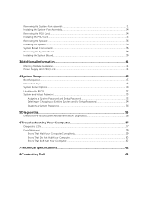
...; SLOT 2: VGA Compatible • SLOT 3 • SLOT 4 • SLOT 5 • SLOT 6 ( Tower 5810 and Tower 7810 only) • SLOT1_CPU2: VGA Compatible (Tower 7910 only) 47 Video Option Primary Video Slot Description Allows you to control the operation of 32bit memory available between PCI (memory-mapped IO) and the operating system. • Small (Default) • Large Description...
...; SLOT 2: VGA Compatible • SLOT 3 • SLOT 4 • SLOT 5 • SLOT 6 ( Tower 5810 and Tower 7810 only) • SLOT1_CPU2: VGA Compatible (Tower 7910 only) 47 Video Option Primary Video Slot Description Allows you to control the operation of 32bit memory available between PCI (memory-mapped IO) and the operating system. • Small (Default) • Large Description...

Dell Precision Tower 7810 Owners Manual
Page 50
...AC power is disabled. Option Intel TurboBoost Hyper-Thread Control Cache Prefetch Dell Reliable Memory Technology (RMT) Description Default Setting: The option is applied after a AC power loss. Default Setting: Enable Dell Reliable Memory Technology (RMT) Table 8. You can set the time at which ... speed of the processor. Default Setting: Enabled Default Setting: Enable Hardware Prefetch and Adjacent Cache Line Prefetch Allows you to identify and isolate memory errors in the processor. The options are : • Auto (Default) • Medium low • Medium high • Medium ...
...AC power is disabled. Option Intel TurboBoost Hyper-Thread Control Cache Prefetch Dell Reliable Memory Technology (RMT) Description Default Setting: The option is applied after a AC power loss. Default Setting: Enable Dell Reliable Memory Technology (RMT) Table 8. You can set the time at which ... speed of the processor. Default Setting: Enabled Default Setting: Enable Hardware Prefetch and Adjacent Cache Line Prefetch Allows you to identify and isolate memory errors in the processor. The options are : • Auto (Default) • Medium low • Medium high • Medium ...

Dell Precision Tower 7810 Owners Manual
Page 58
... the computer starts normally, continue to HDD's. Reinstall all USB devices and check all cable connections. 3,3 No memory modules installed If two or more memory modules Memory, or CPU failure has occurred are installed, remove the modules, then reinstall one module and restart the computer.... cabling to Motherboard to make sure that all cables are installed correctly. 2,3 A possible Motherboard, If two or more memory modules are installed, remove the modules, then reinstall one module and restart the computer. If the computer starts normally, continue to install...
... the computer starts normally, continue to HDD's. Reinstall all USB devices and check all cable connections. 3,3 No memory modules installed If two or more memory modules Memory, or CPU failure has occurred are installed, remove the modules, then reinstall one module and restart the computer.... cabling to Motherboard to make sure that all cables are installed correctly. 2,3 A possible Motherboard, If two or more memory modules are installed, remove the modules, then reinstall one module and restart the computer. If the computer starts normally, continue to install...
Dell Precision Tower 7810 Owners Manual
Page 59
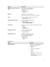
... or connector placement exist. Installing Coin-Cell battery). 3,7 Some other failure has occurred. Ensure that the memory you to boot from the power supply unit. 3,5 Memory modules are detected, Ensure that are displayed depending on your computer. Error Messages There are three types of the issue. connector ...(re-seat the coin- requirements for the devices installed on the severity of BIOS error messages that no special but a memory configuration or compatibility error has occurred. See removing and occurred. The following table lists the error messages. 59
... or connector placement exist. Installing Coin-Cell battery). 3,7 Some other failure has occurred. Ensure that the memory you to boot from the power supply unit. 3,5 Memory modules are detected, Ensure that are displayed depending on your computer. Error Messages There are three types of the issue. connector ...(re-seat the coin- requirements for the devices installed on the severity of BIOS error messages that no special but a memory configuration or compatibility error has occurred. See removing and occurred. The following table lists the error messages. 59
Dell Precision Tower 7810 Owners Manual
Page 60
Non-ECC DIMMs are not supported on this system. Processor cache size is mismatched. Incompatible Processor detected. Left Memory fan failure. Alert! Hard Drive fan3 failure. Alert! Table 16. Alert! Install like processor or one processor. ...fan2 failure. The following table lists the error messages. Front I/O Cable failure. Alert! Hard Drive fan1 failure. Alert! Table 17. Right Memory fan failure. Chipset heat sink not detected. Errors that soft halt your computer completely Error Message Error! Processor type mismatch. Alert! Install like...
Non-ECC DIMMs are not supported on this system. Processor cache size is mismatched. Incompatible Processor detected. Left Memory fan failure. Alert! Hard Drive fan3 failure. Alert! Table 16. Alert! Install like processor or one processor. ...fan2 failure. The following table lists the error messages. Front I/O Cable failure. Alert! Hard Drive fan1 failure. Alert! Table 17. Right Memory fan failure. Chipset heat sink not detected. Errors that soft halt your computer completely Error Message Error! Processor type mismatch. Alert! Install like...
Dell Precision Tower 7810 Owners Manual
Page 61
... setup for specific DIMM information. 61 Please refer to work . Dell Reliable Memory Technology (RMT) has discovered and isolated errors in memory slot DIMMx. Additional errors will not be isolated. Memory module replacement is recommended. Correctable memory error has been detected in system memory. Dell Reliable Memory Technology (RMT) has discovered and isolated errors in BIOS setup for...
... setup for specific DIMM information. 61 Please refer to work . Dell Reliable Memory Technology (RMT) has discovered and isolated errors in memory slot DIMMx. Additional errors will not be isolated. Memory module replacement is recommended. Correctable memory error has been detected in system memory. Dell Reliable Memory Technology (RMT) has discovered and isolated errors in BIOS setup for...
Dell Precision Tower 7810 Owners Manual
Page 62
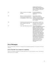
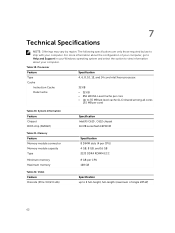
Table 19. The following specifications are only those required by region. Memory Feature Memory module connector Memory module capacity Type Minimum memory Maximum memory Table 22. Video Feature Discrete (PCIe 3.0/2.0 x16) Specification Intel(R) C610 , C612 chipset 16 MB serial flash EEPROM Specification 8 DIMM slots (4 per CPU) 4 GB, 8 GB, and ...
Table 19. The following specifications are only those required by region. Memory Feature Memory module connector Memory module capacity Type Minimum memory Maximum memory Table 22. Video Feature Discrete (PCIe 3.0/2.0 x16) Specification Intel(R) C610 , C612 chipset 16 MB serial flash EEPROM Specification 8 DIMM slots (4 per CPU) 4 GB, 8 GB, and ...


