Quick Reference Guide
Page 5
Some features or media may not be found at support.dell.com. • How to remove and replace parts Dell Precision™ User's Guide • Specifications Microsoft® Windows® XP and Microsoft • How to configure system settings Windows Vista™ Help and Support Center &#...
Some features or media may not be found at support.dell.com. • How to remove and replace parts Dell Precision™ User's Guide • Specifications Microsoft® Windows® XP and Microsoft • How to configure system settings Windows Vista™ Help and Support Center &#...

Quick Reference Guide
Page 23
... channels, as needed. Do not use a special screen-cleaning tissue or solution suitable for the monitor's antistatic coating. • Wipe the keyboard, computer, and plastic part of the monitor with a soft cleaning cloth moistened with a soap or alcohol solution. Cleaning Your Computer CAUTION: Before you clean your mouse counterclockwise, and then...
... channels, as needed. Do not use a special screen-cleaning tissue or solution suitable for the monitor's antistatic coating. • Wipe the keyboard, computer, and plastic part of the monitor with a soft cleaning cloth moistened with a soap or alcohol solution. Cleaning Your Computer CAUTION: Before you clean your mouse counterclockwise, and then...
Quick Reference Guide
Page 35
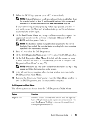
... avoid possible keyboard failure, press and release in the system setup program. 7 Press to select the Dell Diagnostics. 8 At the Dell Diagnostics Menu, press to select the Dell Diagnostics. 9 At the Dell Diagnostics Main Menu, left-click with the mouse, or press and then , to the boot sequence ... Performs a quick test of tracing the problem quickly. Upon restart, the computer boots according to select the test you see "Dell Diagnostics Main Menu" on the keyboard is held down your part. NOTE: Keyboard failure may result when a key on page 35). Quick Reference Guide 35
... avoid possible keyboard failure, press and release in the system setup program. 7 Press to select the Dell Diagnostics. 8 At the Dell Diagnostics Menu, press to select the Dell Diagnostics. 9 At the Dell Diagnostics Main Menu, left-click with the mouse, or press and then , to the boot sequence ... Performs a quick test of tracing the problem quickly. Upon restart, the computer boots according to select the test you see "Dell Diagnostics Main Menu" on the keyboard is held down your part. NOTE: Keyboard failure may result when a key on page 35). Quick Reference Guide 35
Quick Reference Guide
Page 37
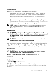
... tips when you troubleshoot your computer: • If you added or removed a part before the problem started, review the installation procedures and ensure that the part is correctly installed. • If a peripheral device does not work properly, contact Dell (see "Contacting Dell" in your antivirus software to check for the Windows default view, so...
... tips when you troubleshoot your computer: • If you added or removed a part before the problem started, review the installation procedures and ensure that the part is correctly installed. • If a peripheral device does not work properly, contact Dell (see "Contacting Dell" in your antivirus software to check for the Windows default view, so...
Quick Reference Guide
Page 52
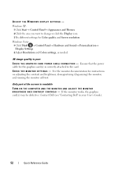
... quality and Screen resolution. If the monitor works, the graphics card(s) may be defective. ADJUST THE WINDOWS DISPLAY SETTINGS - Contact Dell (see "Contacting Dell" in your User's Guide). 52 Quick Reference Guide Only part of the screen is readable TURN ON THE COMPUTER AND THE MONITOR AND ADJUST THE MONITOR B R I N G S - Windows XP: 1 Click...
... quality and Screen resolution. If the monitor works, the graphics card(s) may be defective. ADJUST THE WINDOWS DISPLAY SETTINGS - Contact Dell (see "Contacting Dell" in your User's Guide). 52 Quick Reference Guide Only part of the screen is readable TURN ON THE COMPUTER AND THE MONITOR AND ADJUST THE MONITOR B R I N G S - Windows XP: 1 Click...

User's Guide
Page 8
12 Adding and Replacing Parts 139 Before You Begin 139 Recommended Tools 139 Turning Off Your Computer 139 Before Working Inside Your Computer 140 Removing the Computer Cover and Front ...
12 Adding and Replacing Parts 139 Before You Begin 139 Recommended Tools 139 Turning Off Your Computer 139 Before Working Inside Your Computer 140 Removing the Computer Cover and Front ...

User's Guide
Page 93
...the Product Information Guide. Troubleshooting 93 9 Troubleshooting Solving Problems Follow these tips when you troubleshoot your computer: • If you set your Dell™ computer to the Windows Classic view. Battery Problems CAUTION: There is properly connected. • If an error message appears on ...start-up, replace the battery. This message may not apply if you added or removed a part before the problem started, review the installation procedures and ensure that the part is incorrectly installed. Drive Problems CAUTION: Before you begin any of a new battery exploding if...
...the Product Information Guide. Troubleshooting 93 9 Troubleshooting Solving Problems Follow these tips when you troubleshoot your computer: • If you set your Dell™ computer to the Windows Classic view. Battery Problems CAUTION: There is properly connected. • If an error message appears on ...start-up, replace the battery. This message may not apply if you added or removed a part before the problem started, review the installation procedures and ensure that the part is incorrectly installed. Drive Problems CAUTION: Before you begin any of a new battery exploding if...
User's Guide
Page 125
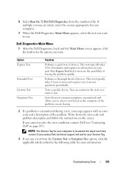
...is encountered during a test, a message appears with an error code and a description of each test screen. NOTE: The Service Tag for your part. This test typically takes 10 to 20 minutes and requires no interaction on the screen. Performs a thorough check of the problem you cannot resolve the...you are listed, select the version appropriate for your Service Tag. 3 If you run . Tests a specific device. 6 Select Run the 32 Bit Dell Diagnostics from the Custom Test or Symptom Tree option, click the applicable tab described in the following table for more and requires you want to...
...is encountered during a test, a message appears with an error code and a description of each test screen. NOTE: The Service Tag for your part. This test typically takes 10 to 20 minutes and requires no interaction on the screen. Performs a thorough check of the problem you cannot resolve the...you are listed, select the version appropriate for your Service Tag. 3 If you run . Tests a specific device. 6 Select Run the 32 Bit Dell Diagnostics from the Custom Test or Symptom Tree option, click the applicable tab described in the following table for more and requires you want to...

User's Guide
Page 139
...Off Your Computer" on page 139 and "Before Working Inside Your Computer" on page 140. • You have read the safety information in the Dell™ Product Information Guide. • A component can be replaced or-if purchased separately-installed by performing the removal procedure in your computer. 1 ...operating system: a Save and close all open files and exit all open programs before you turn off your computer. Adding and Replacing Parts 139 12 Adding and Replacing Parts Before You Begin This chapter provides procedures for removing and installing the components in reverse order.
...Off Your Computer" on page 139 and "Before Working Inside Your Computer" on page 140. • You have read the safety information in the Dell™ Product Information Guide. • A component can be replaced or-if purchased separately-installed by performing the removal procedure in your computer. 1 ...operating system: a Save and close all open files and exit all open programs before you turn off your computer. Adding and Replacing Parts 139 12 Adding and Replacing Parts Before You Begin This chapter provides procedures for removing and installing the components in reverse order.

User's Guide
Page 140
...processor by its edges, not by its metal mounting bracket. If your computer (see "Turning Off Your Computer" on page 139). 140 Adding and Replacing Parts NOTICE: Handle components and cards with locking tabs; if you disconnect the cable. In the Microsoft Windows Vista™ operating system, click the Windows Vista...repairs on a card. The computer turns off after the operating system shutdown process is complete. 2 Ensure that the work surface is not covered by Dell is flat and clean to prevent the computer cover from potential damage and to help to ensure your computer.
...processor by its edges, not by its metal mounting bracket. If your computer (see "Turning Off Your Computer" on page 139). 140 Adding and Replacing Parts NOTICE: Handle components and cards with locking tabs; if you disconnect the cable. In the Microsoft Windows Vista™ operating system, click the Windows Vista...repairs on a card. The computer turns off after the operating system shutdown process is complete. 2 Ensure that the work surface is not covered by Dell is flat and clean to prevent the computer cover from potential damage and to help to ensure your computer.

User's Guide
Page 141
... Front Panel Removing the Computer Cover CAUTION: Before you have installed a security cable, remove it is resting. 3 Lay your computer's electronic components. Adding and Replacing Parts 141
... Front Panel Removing the Computer Cover CAUTION: Before you have installed a security cable, remove it is resting. 3 Lay your computer's electronic components. Adding and Replacing Parts 141

User's Guide
Page 142
1 2 3 1 cover latch release 3 cover hinges 2 computer cover 5 Locate the three hinge tabs on the edge of the computer. 6 Grip the sides of the computer cover and pivot the cover up, using the hinges as leverage points. 7 Release the cover from the hinge tabs and set it aside in a secure location. Do not attempt to boot the computer before replacing the computer cover. 142 Adding and Replacing Parts NOTICE: The computer cooling system cannot function properly while the computer cover is not installed.
1 2 3 1 cover latch release 3 cover hinges 2 computer cover 5 Locate the three hinge tabs on the edge of the computer. 6 Grip the sides of the computer cover and pivot the cover up, using the hinges as leverage points. 7 Release the cover from the hinge tabs and set it aside in a secure location. Do not attempt to boot the computer before replacing the computer cover. 142 Adding and Replacing Parts NOTICE: The computer cooling system cannot function properly while the computer cover is not installed.

User's Guide
Page 143
... any of your computer's electronic components. NOTICE: To prevent static damage to remove the front panel. 1 2 1 front-panel release lever 2 front panel Adding and Replacing Parts 143
... any of your computer's electronic components. NOTICE: To prevent static damage to remove the front panel. 1 2 1 front-panel release lever 2 front panel Adding and Replacing Parts 143

User's Guide
Page 144
... can do so by touching an unpainted metal surface on the front of the computer. 1 2 1 front-panel release lever 2 front panel 144 Adding and Replacing Parts Replacing the Front Panel and Computer Cover CAUTION: Before you touch any of the procedures in this section, follow the safety instructions in the Product...
... can do so by touching an unpainted metal surface on the front of the computer. 1 2 1 front-panel release lever 2 front panel 144 Adding and Replacing Parts Replacing the Front Panel and Computer Cover CAUTION: Before you touch any of the procedures in this section, follow the safety instructions in the Product...

User's Guide
Page 145
... is locked. Gently pull the power cables toward you so that they do not get caught underneath the drives. 2 Ensure that no tools or extra parts are connected, and fold cables out of step 3. 1 1 computer cover 2 2 computer base Adding and Replacing...
... is locked. Gently pull the power cables toward you so that they do not get caught underneath the drives. 2 Ensure that no tools or extra parts are connected, and fold cables out of step 3. 1 1 computer cover 2 2 computer base Adding and Replacing...

User's Guide
Page 146
... computer, discharge static electricity from the electrical outlet before you touch any of your network administrator for information on the computer. 146 Adding and Replacing Parts CAUTION: To guard against electrical shock, always unplug your computer from your body before opening the cover. You can do so by someone else, contact...
... computer, discharge static electricity from the electrical outlet before you touch any of your network administrator for information on the computer. 146 Adding and Replacing Parts CAUTION: To guard against electrical shock, always unplug your computer from your body before opening the cover. You can do so by someone else, contact...

User's Guide
Page 147
Adding and Replacing Parts 147 I/O-Panel Components 1 2 6 3 4 5 1 IEEE 1394 connector 2 USB ports (2) 3 diagnostic, hard-drive access, and 4 microphone connector network integrity lights 5 headphone connector 6 front-panel air temperature sensor NOTICE: The front-panel temperature sensor cable must be installed in this connector at all times while your computer is running or thermal problems may result.
Adding and Replacing Parts 147 I/O-Panel Components 1 2 6 3 4 5 1 IEEE 1394 connector 2 USB ports (2) 3 diagnostic, hard-drive access, and 4 microphone connector network integrity lights 5 headphone connector 6 front-panel air temperature sensor NOTICE: The front-panel temperature sensor cable must be installed in this connector at all times while your computer is running or thermal problems may result.

User's Guide
Page 148
.... 7 Disconnect the front fan and the card fan from the card fan and the memory-riser support structure. Removing the I /O panel. 148 Adding and Replacing Parts d Set the riser aside. 5 Loosen the captive thumbscrews that secure the memory shroud and lift to avoid injury;
.... 7 Disconnect the front fan and the card fan from the card fan and the memory-riser support structure. Removing the I /O panel. 148 Adding and Replacing Parts d Set the riser aside. 5 Loosen the captive thumbscrews that secure the memory shroud and lift to avoid injury;

User's Guide
Page 149
1 2 1 I/O panel 2 mounting screws 11 Remove the mounting screws from the I/O panel. 12 Lift to remove the I /O Panel" on page 148) in place, secured by the screw that you replace all cables originally attached to the chassis. Replacing the I/O Panel NOTICE: Ensure that fastens the I/O panel to the I/O panel or you may experience computer problems. Follow the removal procedure ("Removing the I /O panel from the computer. Ensure that the plastic piece that fits over the screw hole is in reverse order. Adding and Replacing Parts 149
1 2 1 I/O panel 2 mounting screws 11 Remove the mounting screws from the I/O panel. 12 Lift to remove the I /O Panel" on page 148) in place, secured by the screw that you replace all cables originally attached to the chassis. Replacing the I/O Panel NOTICE: Ensure that fastens the I/O panel to the I/O panel or you may experience computer problems. Follow the removal procedure ("Removing the I /O panel from the computer. Ensure that the plastic piece that fits over the screw hole is in reverse order. Adding and Replacing Parts 149
User's Guide
Page 150
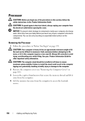
... your Product Information Guide for other important safety information. You can be installed at all times to access the heatsink screws. 150 Adding and Replacing Parts Seek assistance before opening the cover. this section, follow the safety instructions in "Before You Begin" on page 139. Removing the Processor 1 Follow the procedures...
... your Product Information Guide for other important safety information. You can be installed at all times to access the heatsink screws. 150 Adding and Replacing Parts Seek assistance before opening the cover. this section, follow the safety instructions in "Before You Begin" on page 139. Removing the Processor 1 Follow the procedures...

