Setup and Features Information Tech Sheet
Page 2
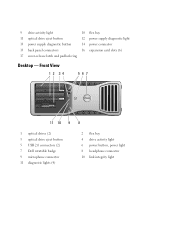
9 drive activity light 10 flex bay 11 optical drive eject button 12 power supply diagnostic light 13 power supply diagnostic button 14 power connector 15 back panel connectors 16 expansion card slots (6) 17 cover-release latch and padlock ring Desktop - Front View 1 2 34 567 11 10 9 8 1 optical drives (2) 3 optical drive eject button 5 USB 2.0 connectors (2) 7 Dell rotatable badge 9 microphone connector 11 diagnostic lights (4) 2 flex bay 4 drive activity light 6 power button, power light 8 headphone connector 10 link integrity light
9 drive activity light 10 flex bay 11 optical drive eject button 12 power supply diagnostic light 13 power supply diagnostic button 14 power connector 15 back panel connectors 16 expansion card slots (6) 17 cover-release latch and padlock ring Desktop - Front View 1 2 34 567 11 10 9 8 1 optical drives (2) 3 optical drive eject button 5 USB 2.0 connectors (2) 7 Dell rotatable badge 9 microphone connector 11 diagnostic lights (4) 2 flex bay 4 drive activity light 6 power button, power light 8 headphone connector 10 link integrity light
Setup and Features Information Tech Sheet
Page 3
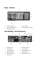
Back View 1 2 3 4 5 1 expansion card slots (6) 3 power supply diagnostic light 5 back panel connectors 2 power connector 4 power supply diagnostic button Tower and Desktop - Desktop - Back Panel Connectors 1 2 34 5 67 11 1 parallel connector 3 eSATA connector 5 network activity light 7 link integrity light 9 USB 2.0 connectors (6) 11 serial connector 8 10 9 2 PS/2 mouse connector 4 line-out connector 6 network adapter connector 8 line-in connector 10 PS/2 keyboard connector
Back View 1 2 3 4 5 1 expansion card slots (6) 3 power supply diagnostic light 5 back panel connectors 2 power connector 4 power supply diagnostic button Tower and Desktop - Desktop - Back Panel Connectors 1 2 34 5 67 11 1 parallel connector 3 eSATA connector 5 network activity light 7 link integrity light 9 USB 2.0 connectors (6) 11 serial connector 8 10 9 2 PS/2 mouse connector 4 line-out connector 6 network adapter connector 8 line-in connector 10 PS/2 keyboard connector
Service Manual
Page 14
Adding and Replacing Parts Dell Precision™ T5500 Service Manual Cover Battery Drives Bezel Hard Drive Tray Front Fan Assembly Memory Card Reader Memory Dual Processor Riser (Optional) System Board I/O Data Cable Chassis Intrusion Switch Front Bezel Hard Drive Floppy Drive Optical Drive Expansion Cards Heat Sink and Processor Power Supply
Adding and Replacing Parts Dell Precision™ T5500 Service Manual Cover Battery Drives Bezel Hard Drive Tray Front Fan Assembly Memory Card Reader Memory Dual Processor Riser (Optional) System Board I/O Data Cable Chassis Intrusion Switch Front Bezel Hard Drive Floppy Drive Optical Drive Expansion Cards Heat Sink and Processor Power Supply
Service Manual
Page 15
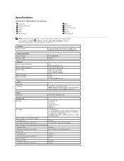
Specifications Dell Precision™ T5500/T5500n Service Manual Processors System Information Memory Video Audio Expansion Bus Drives Connectors Controls and Lights Power Physical Environmental NOTE: Offerings may vary by region. ADI1984A integrated audio Expansion Bus Bus type PCI Express 2.0 PCI 2.3 PCI-X 2.0A SATA 1.0 and 2.0 eSATA 2.0 USB 2.0 Bus speed 133 MB/s (PCI) x1-slot bidirectional speed - 500...
Specifications Dell Precision™ T5500/T5500n Service Manual Processors System Information Memory Video Audio Expansion Bus Drives Connectors Controls and Lights Power Physical Environmental NOTE: Offerings may vary by region. ADI1984A integrated audio Expansion Bus Bus type PCI Express 2.0 PCI 2.3 PCI-X 2.0A SATA 1.0 and 2.0 eSATA 2.0 USB 2.0 Bus speed 133 MB/s (PCI) x1-slot bidirectional speed - 500...
Service Manual
Page 39
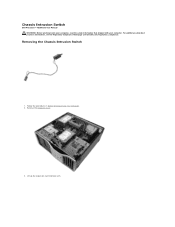
For additional safety best practices information, see the Regulatory Compliance Homepage at www.dell.com/regulatory_compliance. Lift up the expansion card retention arm. Remove the computer cover. 3. Removing the Chassis Intrusion Switch 1. Follow the procedures in Before Working Inside Your Computer. 2. Chassis Intrusion Switch Dell Precision™ T5500 Service Manual WARNING: Before working inside your computer, read the safety information that shipped with your computer.
For additional safety best practices information, see the Regulatory Compliance Homepage at www.dell.com/regulatory_compliance. Lift up the expansion card retention arm. Remove the computer cover. 3. Removing the Chassis Intrusion Switch 1. Follow the procedures in Before Working Inside Your Computer. 2. Chassis Intrusion Switch Dell Precision™ T5500 Service Manual WARNING: Before working inside your computer, read the safety information that shipped with your computer.

Service Manual
Page 66
Rotate the expansion card retention arm toward the outside of the computer. 5. Disconnect the power supply cable from the power supply. 4.
Rotate the expansion card retention arm toward the outside of the computer. 5. Disconnect the power supply cable from the power supply. 4.
Service Manual
Page 69
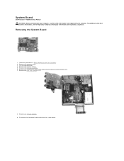
... the expansion card retention arm. 7. Removing the System Board 1. Follow the procedures in Before Working Inside Your Computer. 2. Remove the heat sink and processor. 8. Remove the computer cover. 3. Disconnect the front panel audio cable from the system board. Lift the hard drive tray. 4. Remove the front fan assembly. 6. System Board Dell Precision™ T5500...
... the expansion card retention arm. 7. Removing the System Board 1. Follow the procedures in Before Working Inside Your Computer. 2. Remove the heat sink and processor. 8. Remove the computer cover. 3. Disconnect the front panel audio cable from the system board. Lift the hard drive tray. 4. Remove the front fan assembly. 6. System Board Dell Precision™ T5500...

Service Manual
Page 76
Expansion Cards Dell Precision™ T5500 Service Manual WARNING: Before working inside your computer, read the safety information that shipped with your computer. For additional safety best practices information, see the Regulatory Compliance Homepage at www.dell.com/regulatory_compliance. Squeeze the release tabs, then lift the expansion card retention arm away from the computer. Removing an Expansion Card 1. Follow the procedures in Before Working Inside Your Computer. 2. Remove the computer cover. 3.
Expansion Cards Dell Precision™ T5500 Service Manual WARNING: Before working inside your computer, read the safety information that shipped with your computer. For additional safety best practices information, see the Regulatory Compliance Homepage at www.dell.com/regulatory_compliance. Squeeze the release tabs, then lift the expansion card retention arm away from the computer. Removing an Expansion Card 1. Follow the procedures in Before Working Inside Your Computer. 2. Remove the computer cover. 3.

Service Manual
Page 77
Remove the expansion card from the computer. Pull back the expansion card retention clip. 4. 4.
Remove the expansion card from the computer. Pull back the expansion card retention clip. 4. 4.


