Replacing the Hard-Drive Tray
Page 3
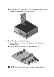
b Lift the filler panel and slide it out of the hard-drive tray. NOTE: Retain the filler panel to the replacement hard-drive tray. lift the hard-drive tray up and away from the computer. 6 Install the replacement hard-drive tray: a Remove the screws that secure the hard-drive tray to the chassis; b Remove the screws that secure the filler panel to install a second hard drive at a later time.
b Lift the filler panel and slide it out of the hard-drive tray. NOTE: Retain the filler panel to the replacement hard-drive tray. lift the hard-drive tray up and away from the computer. 6 Install the replacement hard-drive tray: a Remove the screws that secure the hard-drive tray to the chassis; b Remove the screws that secure the filler panel to install a second hard drive at a later time.
Replacing the Hard-Drive Tray
Page 4
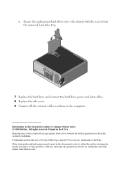
... used in this text: Dell, the DELL logo, and Dell Precision are trademarks of Dell Inc. Other trademarks and trade names may be used in this document is strictly forbidden. c Secure the replacement hard-drive tray to change without the written permission of Dell Inc. disclaims any manner whatsoever... document to refer to either the entities claiming the marks and names or their products. Dell Inc. Information in any proprietary interest in the U.S.A. is subject to the chassis with the screws from the removed hard-drive tray. 7 Replace the hard drive and ...
... used in this text: Dell, the DELL logo, and Dell Precision are trademarks of Dell Inc. Other trademarks and trade names may be used in this document is strictly forbidden. c Secure the replacement hard-drive tray to change without the written permission of Dell Inc. disclaims any manner whatsoever... document to refer to either the entities claiming the marks and names or their products. Dell Inc. Information in any proprietary interest in the U.S.A. is subject to the chassis with the screws from the removed hard-drive tray. 7 Replace the hard drive and ...
Service Manual
Page 5
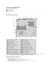
About Your System Board Dell Precision™ T5500 Service Manual System Board Schematic Clearing Forgotten Passwords Clearing CMOS Settings System Board Schematic 1 Main Power Connector (POWER1) 15 Type A USB Port (INT_USB2) 2...Connector (FAN_HDD) 18 >Primary Processor Connector (CPU1) 5 Floppy Drive (DSKT) 19 Power Connector (POWER_CPU1) 6 Front Panel Connector (FRONTPANEL) 20 Front Fan Connector (FAN_FRONT) 7 Chassis Intrusion Header (INTRUDER) 21 Card Cage Fan (FAN_CCAG) 8 PCI-X Card Slot (SLOT6) 22 Memory Module Connectors (DIMM1-6) 9 PCI Card Slot (SLOT5) 23 Optional Serial/...
About Your System Board Dell Precision™ T5500 Service Manual System Board Schematic Clearing Forgotten Passwords Clearing CMOS Settings System Board Schematic 1 Main Power Connector (POWER1) 15 Type A USB Port (INT_USB2) 2...Connector (FAN_HDD) 18 >Primary Processor Connector (CPU1) 5 Floppy Drive (DSKT) 19 Power Connector (POWER_CPU1) 6 Front Panel Connector (FRONTPANEL) 20 Front Fan Connector (FAN_FRONT) 7 Chassis Intrusion Header (INTRUDER) 21 Card Cage Fan (FAN_CCAG) 8 PCI-X Card Slot (SLOT6) 22 Memory Module Connectors (DIMM1-6) 9 PCI Card Slot (SLOT5) 23 Optional Serial/...
Service Manual
Page 14
Adding and Replacing Parts Dell Precision™ T5500 Service Manual Cover Battery Drives Bezel Hard Drive Tray Front Fan Assembly Memory Card Reader Memory Dual Processor Riser (Optional) System Board I/O Data Cable Chassis Intrusion Switch Front Bezel Hard Drive Floppy Drive Optical Drive Expansion Cards Heat Sink and Processor Power Supply
Adding and Replacing Parts Dell Precision™ T5500 Service Manual Cover Battery Drives Bezel Hard Drive Tray Front Fan Assembly Memory Card Reader Memory Dual Processor Riser (Optional) System Board I/O Data Cable Chassis Intrusion Switch Front Bezel Hard Drive Floppy Drive Optical Drive Expansion Cards Heat Sink and Processor Power Supply
Service Manual
Page 39
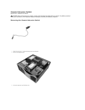
Lift up the expansion card retention arm. Removing the Chassis Intrusion Switch 1. Chassis Intrusion Switch Dell Precision™ T5500 Service Manual WARNING: Before working inside your computer, read the safety information that shipped with your computer. Remove the computer cover. 3. Follow the procedures in Before Working Inside Your Computer. 2. For additional safety best practices information, see the Regulatory Compliance Homepage at www.dell.com/regulatory_compliance.
Lift up the expansion card retention arm. Removing the Chassis Intrusion Switch 1. Chassis Intrusion Switch Dell Precision™ T5500 Service Manual WARNING: Before working inside your computer, read the safety information that shipped with your computer. Remove the computer cover. 3. Follow the procedures in Before Working Inside Your Computer. 2. For additional safety best practices information, see the Regulatory Compliance Homepage at www.dell.com/regulatory_compliance.

Service Manual
Page 50
6. Slide the optical drive out of the front of the chassis, and remove from the computer.
6. Slide the optical drive out of the front of the chassis, and remove from the computer.

Service Manual
Page 73
Remove the dual processor riser. 17. Remove the eight screws that secure the system board to the computer chassis. 16.
Remove the dual processor riser. 17. Remove the eight screws that secure the system board to the computer chassis. 16.


