
Setup and Features Information Tech Sheet
Page 6
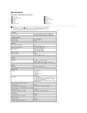
For a complete and current listing of the specifications for your computer, go to ship with your computer. Processor Type: System Information System chipset Data bus width Dual-Core Intel® Xeon® Processor 5500 series Quad-Core Intel® Xeon® Processor 5500 series Intel 5500/5520 64 bits Specifications NOTE: The following specifications are only those required by law to support.dell.com. 3 Connect the network cable. 4 Connect the modem (if installed). 5 Connect the power cable(s). 6 Press the power buttons on the monitor and the computer.
For a complete and current listing of the specifications for your computer, go to ship with your computer. Processor Type: System Information System chipset Data bus width Dual-Core Intel® Xeon® Processor 5500 series Quad-Core Intel® Xeon® Processor 5500 series Intel 5500/5520 64 bits Specifications NOTE: The following specifications are only those required by law to support.dell.com. 3 Connect the network cable. 4 Connect the modem (if installed). 5 Connect the power cable(s). 6 Press the power buttons on the monitor and the computer.
Service Manual
Page 2
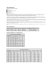
...533 MHz 1066 Million P C 3-8 5 0 0 8533 MB/s DDR3-1333 166 MHz 6 ns 667 MHz 1333 Million PC3-10600 10667 MB/s Supported Memory Configurations Single Processor Memory Configurations Size DIMM DIMM1 DIMM2 DIMM3 DIMM4 DIMM5 DIMM6 (GB) Ranks 3 SR 1 GB 1 GB 1 GB 4 SR 1 GB 1 GB 1 GB 1 ...primary benefit of maximum 16 gigabyte in size. Also, the DDR3 standard allows for most DDR3 chips. About Memory Dell Precision™ T5500 Service Manual Memory Modules Supported Memory Configurations Memory Subsystem Memory Slots Memory Population Rules WARNING: Before working inside your ...
...533 MHz 1066 Million P C 3-8 5 0 0 8533 MB/s DDR3-1333 166 MHz 6 ns 667 MHz 1333 Million PC3-10600 10667 MB/s Supported Memory Configurations Single Processor Memory Configurations Size DIMM DIMM1 DIMM2 DIMM3 DIMM4 DIMM5 DIMM6 (GB) Ranks 3 SR 1 GB 1 GB 1 GB 4 SR 1 GB 1 GB 1 GB 1 ...primary benefit of maximum 16 gigabyte in size. Also, the DDR3 standard allows for most DDR3 chips. About Memory Dell Precision™ T5500 Service Manual Memory Modules Supported Memory Configurations Memory Subsystem Memory Slots Memory Population Rules WARNING: Before working inside your ...
Service Manual
Page 3
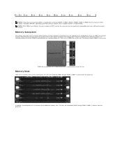
... Slots There are six DIMM slots on the riser. There are six memory slots on the system board. DIMM slot configuration for a single processor or a second processor on the riser, for a total of three DDR3 memory channels attached to 800 MHz. The slots are electrically incompatible and have six DIMM ...slots (two per channel) attached to the primary processor located on the system board. 72 DR 8 GB 8 GB 8 GB 8 GB 8 GB 8 GB 8 GB 8 GB 8 GB NOTE: If more than one Quad ...
... Slots There are six DIMM slots on the riser. There are six memory slots on the system board. DIMM slot configuration for a single processor or a second processor on the riser, for a total of three DDR3 memory channels attached to 800 MHz. The slots are electrically incompatible and have six DIMM ...slots (two per channel) attached to the primary processor located on the system board. 72 DR 8 GB 8 GB 8 GB 8 GB 8 GB 8 GB 8 GB 8 GB 8 GB NOTE: If more than one Quad ...

Service Manual
Page 4
... to be installed on Riser) l If configuration contains DIMMs of one 2GB DIMM and two 1GB DIMMs, the population would be populated farthest from the processor first. Memory Population Rules Your computer requires DIMMs within a configuration should generally be populated before populating multiple DIMMs per channel.
... to be installed on Riser) l If configuration contains DIMMs of one 2GB DIMM and two 1GB DIMMs, the population would be populated farthest from the processor first. Memory Population Rules Your computer requires DIMMs within a configuration should generally be populated before populating multiple DIMMs per channel.
Service Manual
Page 5
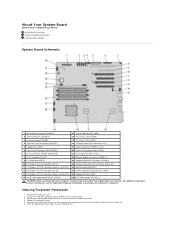
... the Regulatory Compliance Homepage at www.dell.com/regulatory_compliance. Locate the 4-pin password connector (PSWD) on . 6. About Your System Board Dell Precision™ T5500 Service Manual System Board Schematic Clearing ...Forgotten Passwords Clearing CMOS Settings System Board Schematic 1 Main Power Connector (POWER1) 15 Type A USB Port (INT_USB2) 2 SATA Connectors (SATA0-4) 16 CPU Riser 2 (CPU2_RSR2) 3 Password Jumper (PSWD) 17 CPU Riser 1 (CPU_RSR1) 4 Hard Drive Fan Connector (FAN_HDD) 18 >Primary Processor...
... the Regulatory Compliance Homepage at www.dell.com/regulatory_compliance. Locate the 4-pin password connector (PSWD) on . 6. About Your System Board Dell Precision™ T5500 Service Manual System Board Schematic Clearing ...Forgotten Passwords Clearing CMOS Settings System Board Schematic 1 Main Power Connector (POWER1) 15 Type A USB Port (INT_USB2) 2 SATA Connectors (SATA0-4) 16 CPU Riser 2 (CPU2_RSR2) 3 Password Jumper (PSWD) 17 CPU Riser 1 (CPU_RSR1) 4 Hard Drive Fan Connector (FAN_HDD) 18 >Primary Processor...
Service Manual
Page 14
Adding and Replacing Parts Dell Precision™ T5500 Service Manual Cover Battery Drives Bezel Hard Drive Tray Front Fan Assembly Memory Card Reader Memory Dual Processor Riser (Optional) System Board I/O Data Cable Chassis Intrusion Switch Front Bezel Hard Drive Floppy Drive Optical Drive Expansion Cards Heat Sink and Processor Power Supply
Adding and Replacing Parts Dell Precision™ T5500 Service Manual Cover Battery Drives Bezel Hard Drive Tray Front Fan Assembly Memory Card Reader Memory Dual Processor Riser (Optional) System Board I/O Data Cable Chassis Intrusion Switch Front Bezel Hard Drive Floppy Drive Optical Drive Expansion Cards Heat Sink and Processor Power Supply
Service Manual
Page 15
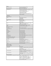
... Information System chipset Data bus width Dual-Core Intel® Xeon® Processor 5500 series Quad-Core Intel® Xeon® Processor 5500 series Intel 5500/5520 64 bits Memory Memory module connectors Memory module capacities Memory type Minimum memory...maximum) 120 pins 32 bits One PCI-X slot Connector pins Connector data width (maximum) 188 pins 64 bits Specifications Dell Precision™ T5500/T5500n Service Manual Processors System Information Memory Video Audio Expansion Bus Drives Connectors Controls and Lights Power Physical Environmental NOTE: Offerings may vary by region...
... Information System chipset Data bus width Dual-Core Intel® Xeon® Processor 5500 series Quad-Core Intel® Xeon® Processor 5500 series Intel 5500/5520 64 bits Memory Memory module connectors Memory module capacities Memory type Minimum memory...maximum) 120 pins 32 bits One PCI-X slot Connector pins Connector data width (maximum) 188 pins 64 bits Specifications Dell Precision™ T5500/T5500n Service Manual Processors System Information Memory Video Audio Expansion Bus Drives Connectors Controls and Lights Power Physical Environmental NOTE: Offerings may vary by region...
Service Manual
Page 16
...: Front fan Card cage fan HDD fan PCI PCI-X PCI Express x8 PCI Express x16 Front panel control (USB included) Front panel audio HDA header Processor Memory Power 12 V Power (Depending on video card) DVI connector Display port RJ-45 connector USB 2.0 compliant Two internal connectors Two in front Six at...
...: Front fan Card cage fan HDD fan PCI PCI-X PCI Express x8 PCI Express x16 Front panel control (USB included) Front panel audio HDA header Processor Memory Power 12 V Power (Depending on video card) DVI connector Display port RJ-45 connector USB 2.0 compliant Two internal connectors Two in front Six at...
Service Manual
Page 44
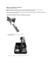
... the computer cover. 3. Lift the hard drive tray. 4. Your computer features an optional dual-processor riser to accommodate dual processor and expanded memory options (see the Regulatory Compliance Homepage at www.dell.com/regulatory_compliance. Memory and Memory Shroud Dell Precision™ T5500 Service Manual WARNING: Before working inside your computer, read the safety information that shipped...
... the computer cover. 3. Lift the hard drive tray. 4. Your computer features an optional dual-processor riser to accommodate dual processor and expanded memory options (see the Regulatory Compliance Homepage at www.dell.com/regulatory_compliance. Memory and Memory Shroud Dell Precision™ T5500 Service Manual WARNING: Before working inside your computer, read the safety information that shipped...

Service Manual
Page 52
Removing the Heat Sink and Processor 1. Remove the computer cover. 3. Open the hard drive tray. 4. Heat Sink and Processor Dell Precision™ T5500 Service Manual WARNING: Before working inside your computer, read the safety information that shipped with your computer. Loosen the four captive screws on the heat sink. For additional safety best practices information, see the Regulatory Compliance Homepage at www.dell.com/regulatory_compliance. Follow the procedures in Before Working Inside Your Computer. 2.
Removing the Heat Sink and Processor 1. Remove the computer cover. 3. Open the hard drive tray. 4. Heat Sink and Processor Dell Precision™ T5500 Service Manual WARNING: Before working inside your computer, read the safety information that shipped with your computer. Loosen the four captive screws on the heat sink. For additional safety best practices information, see the Regulatory Compliance Homepage at www.dell.com/regulatory_compliance. Follow the procedures in Before Working Inside Your Computer. 2.

Service Manual
Page 53
Press down and out on the processor release lever to release the processor. 5. Lift the heat sink straight up and remove the heat sink from the computer. 6.
Press down and out on the processor release lever to release the processor. 5. Lift the heat sink straight up and remove the heat sink from the computer. 6.

Service Manual
Page 54
Lift the processor straight up and remove it from the computer. 7. Lift the processor cover. 8.
Lift the processor straight up and remove it from the computer. 7. Lift the processor cover. 8.
Service Manual
Page 56
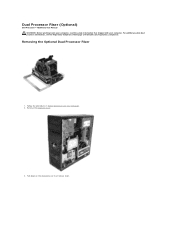
For additional safety best practices information, see the Regulatory Compliance Homepage at www.dell.com/regulatory_compliance. Remove the computer cover. 3. Pull down on the dual processor riser release lever. Dual Processor Riser (Optional) Dell Precision™ T5500 Service Manual WARNING: Before working inside your computer, read the safety information that shipped with your computer. Follow the procedures in Before Working Inside Your Computer. 2. Removing the Optional Dual Processor Riser 1.
For additional safety best practices information, see the Regulatory Compliance Homepage at www.dell.com/regulatory_compliance. Remove the computer cover. 3. Pull down on the dual processor riser release lever. Dual Processor Riser (Optional) Dell Precision™ T5500 Service Manual WARNING: Before working inside your computer, read the safety information that shipped with your computer. Follow the procedures in Before Working Inside Your Computer. 2. Removing the Optional Dual Processor Riser 1.
Service Manual
Page 57
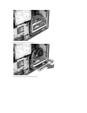
Carefully slide the dual processor riser halfway out. 5. Disconnect the power cable from the dual processor board. 4.
Carefully slide the dual processor riser halfway out. 5. Disconnect the power cable from the dual processor board. 4.

Service Manual
Page 58
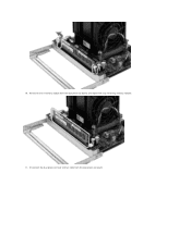
Disconnect the dual processor fan cable from the computer. 7. 6. Remove the dual processor riser completely from the dual processor board.
Disconnect the dual processor fan cable from the computer. 7. 6. Remove the dual processor riser completely from the dual processor board.

Service Manual
Page 59
Gently press down on the blue release tab, remove the dual processor fan assembly from the connector. While pressing on the memory module release tabs to release the first dual processor memory module from the dual processor assembly. 9. 8.
Gently press down on the blue release tab, remove the dual processor fan assembly from the connector. While pressing on the memory module release tabs to release the first dual processor memory module from the dual processor assembly. 9. 8.
Service Manual
Page 60
Disconnect the dual processor heat sink fan cable from the dual processor board, and repeat with any remaining memory modules. 11. 10. Remove the first memory module from the dual processor board.
Disconnect the dual processor heat sink fan cable from the dual processor board, and repeat with any remaining memory modules. 11. 10. Remove the first memory module from the dual processor board.

Service Manual
Page 61
Loosen the four captive screws on the dual processor heat sink/fan assembly. 13. Remove the dual processor heat sink fan assembly from the dual processor riser board. 12.
Loosen the four captive screws on the dual processor heat sink/fan assembly. 13. Remove the dual processor heat sink fan assembly from the dual processor riser board. 12.

Service Manual
Page 62
14. Open the dual processor cover. Release the dual processor cover by pressing down and out on the release arm. 15.
14. Open the dual processor cover. Release the dual processor cover by pressing down and out on the release arm. 15.

Service Manual
Page 63
Remove the dual processor from the dual processor board. 16.
Remove the dual processor from the dual processor board. 16.


