Quick Reference Guide (Multilanguage: English, Japanese, Korean, Simplified Chinese, Traditional Chinese
Page 40
... SYSTEM HAS REPORTED THAT A PARAMETER HAS EXCEEDED ITS NORMAL OPERATING RANGE. N O N - N O T I M E R T I C K I S K E R R O R - Replace the floppy disk with one that the boot sequence information is correct (see "Contacting Dell" in your User's Guide for assistance). A P A R A M E T E R O U T OF RANGE MAY OR MAY NOT INDICATE A POTENTIAL HARD DRIVE PROBLEM. - S.M.A.R.T error, possible HDD failure. S YS T E M D I S K O R D I N T E R R U P T - A chip on the system board...
... SYSTEM HAS REPORTED THAT A PARAMETER HAS EXCEEDED ITS NORMAL OPERATING RANGE. N O N - N O T I M E R T I C K I S K E R R O R - Replace the floppy disk with one that the boot sequence information is correct (see "Contacting Dell" in your User's Guide for assistance). A P A R A M E T E R O U T OF RANGE MAY OR MAY NOT INDICATE A POTENTIAL HARD DRIVE PROBLEM. - S.M.A.R.T error, possible HDD failure. S YS T E M D I S K O R D I N T E R R U P T - A chip on the system board...

Quick Reference Guide (Multilanguage: English, French, Portuguese, Spanish)
Page 40
...RANGE MAY OR MAY NOT INDICATE A POTENTIAL HARD DRIVE PROBLEM. - DELL RECOMMENDS THAT YOU BACK UP YOUR DATA REGULARLY. S.M.A.R.T error, possible HDD failure. N O T I M E R T I C K I S K E R R O R - H A R D - N O B O O T D E V I C E A V A I L U R E - D I S K R E A D F A I L A B L E - HARD DRIVE SELF MONITORING SYSTEM HAS REPORTED THAT A PARAMETER ...remove the floppy disk from drive A and restart the computer. K E Y B O A R D F A I S K E T T E - Replace the floppy disk with one that the boot sequence information is correct (see "Contacting Dell" in your computer. ...
...RANGE MAY OR MAY NOT INDICATE A POTENTIAL HARD DRIVE PROBLEM. - DELL RECOMMENDS THAT YOU BACK UP YOUR DATA REGULARLY. S.M.A.R.T error, possible HDD failure. N O T I M E R T I C K I S K E R R O R - H A R D - N O B O O T D E V I C E A V A I L U R E - D I S K R E A D F A I L A B L E - HARD DRIVE SELF MONITORING SYSTEM HAS REPORTED THAT A PARAMETER ...remove the floppy disk from drive A and restart the computer. K E Y B O A R D F A I S K E T T E - Replace the floppy disk with one that the boot sequence information is correct (see "Contacting Dell" in your computer. ...
Quick Reference Guide (Multilanguage: English, Croatian, Danish, Finnish, Norwegian, Polish, Russian, Swedish)
Page 40
Replace the floppy disk with one that the boot sequence information is correct (see "Contacting Dell" in your User's Guide for assistance). Possible HDD failure during HDD boot test (see "Keyboard Problems" in your User's Guide). Keyboard failure or keyboard cable loose (see "Contacting Dell" in the drive. • If the hard drive is your User's Guide...
Replace the floppy disk with one that the boot sequence information is correct (see "Contacting Dell" in your User's Guide for assistance). Possible HDD failure during HDD boot test (see "Keyboard Problems" in your User's Guide). Keyboard failure or keyboard cable loose (see "Contacting Dell" in the drive. • If the hard drive is your User's Guide...

User's Guide
Page 9
... Connector Pin Assignments . . 149 Removing the Front Panel 154 Chassis Intrusion Switch 155 Removing the Chassis Intrusion Switch 155 Replacing the Chassis Intrusion Switch 156 Resetting the Chassis Intrusion Detector . . . . . 157 Memory 157 Memory Overview 157... Drives 185 Tower Computer Drive Configurations 185 Desktop Computer Drive Configurations 187 About Metal Shields (Present in Some Drive Configurations 188 General Installation Guidelines 189 Hard Drive 191 Removing a Hard Drive (Tower or Desktop Computer 191 Installing a Hard Drive or Adding a Second Optional Hard Drive ...
... Connector Pin Assignments . . 149 Removing the Front Panel 154 Chassis Intrusion Switch 155 Removing the Chassis Intrusion Switch 155 Replacing the Chassis Intrusion Switch 156 Resetting the Chassis Intrusion Detector . . . . . 157 Memory 157 Memory Overview 157... Drives 185 Tower Computer Drive Configurations 185 Desktop Computer Drive Configurations 187 About Metal Shields (Present in Some Drive Configurations 188 General Installation Guidelines 189 Hard Drive 191 Removing a Hard Drive (Tower or Desktop Computer 191 Installing a Hard Drive or Adding a Second Optional Hard Drive ...

User's Guide
Page 10
... Installing an Optional Fourth Hard Drive (Tower Computer 202 Removing an Optional Third Hard Drive (Desktop Computer 203 Installing an Optional Third Hard Drive (Desktop Computer 206 Installing an Additional Fan 210 Drive Panel 212 Removing the Drive Panel (Tower Computer) . . . 213 Replacing the Drive Panel (Tower Computer) . . . 214 Removing the Drive Panel (Desktop Computer) . . 215 Replacing the Drive Panel (Desktop Computer) . . 216...
... Installing an Optional Fourth Hard Drive (Tower Computer 202 Removing an Optional Third Hard Drive (Desktop Computer 203 Installing an Optional Third Hard Drive (Desktop Computer 206 Installing an Additional Fan 210 Drive Panel 212 Removing the Drive Panel (Tower Computer) . . . 213 Replacing the Drive Panel (Tower Computer) . . . 214 Removing the Drive Panel (Desktop Computer) . . 215 Replacing the Drive Panel (Desktop Computer) . . 216...

User's Guide
Page 45
...drive, the data is equal to each drive in the configuration. About RAID Configurations 45 A replacement drive can then be rebuilt using the data from each segment across multiple drives. Unlike a RAID level 1 configuration which writes to the surviving drive... 3 segment 4 segment 5 segment 6 hard drive 1 segment 1 duplicated segment 2 duplicated segment 3 duplicated segment 4 duplicated segment 5 duplicated segment 6 duplicated hard drive 2 If a drive failure occurs, subsequent read and write operations are directed to one other drives. A RAID level 5 configuration has higher...
...drive, the data is equal to each drive in the configuration. About RAID Configurations 45 A replacement drive can then be rebuilt using the data from each segment across multiple drives. Unlike a RAID level 1 configuration which writes to the surviving drive... 3 segment 4 segment 5 segment 6 hard drive 1 segment 1 duplicated segment 2 duplicated segment 3 duplicated segment 4 duplicated segment 5 duplicated segment 6 duplicated hard drive 2 If a drive failure occurs, subsequent read and write operations are directed to one other drives. A RAID level 5 configuration has higher...

User's Guide
Page 46
...replacement drive can then be rebuilt using the data from each drive in the configuration multiplied by three. Unlike a RAID level 1 configuration which places data from the surviving drives. NOTE: In a RAID level 5 configuration, the size of the smallest drive in increments which writes to one other drives... hard drive 1 segment 1 striped across at least 3 drives segment 2 striped across at least 3 drives segment 3 striped across at least 3 drives segment 4 striped across at least 3 drives segment 5 striped across at least 3 drives hard drives 2, 3 (and optionally, 4) If a drive ...
...replacement drive can then be rebuilt using the data from each drive in the configuration multiplied by three. Unlike a RAID level 1 configuration which places data from the surviving drives. NOTE: In a RAID level 5 configuration, the size of the smallest drive in increments which writes to one other drives... hard drive 1 segment 1 striped across at least 3 drives segment 2 striped across at least 3 drives segment 3 striped across at least 3 drives segment 4 striped across at least 3 drives segment 5 striped across at least 3 drives hard drives 2, 3 (and optionally, 4) If a drive ...

User's Guide
Page 47
... your computer. A replacement drive can use one of the configuration is performed before you may want to configure your computer for RAID level 10 segment 1 segment 2 segment 3 segment 4 segment 5 segment 6 hard drive 1 segment 1 striped across 4 drives segment 2 striped across 4 drives segment 3 striped across 4 drives segment 4 striped across 4 drives segment 5 striped across 4 drives segment 6 striped across 4 drives hard drives 2, 3, and 4 If a drive failure occurs...
... your computer. A replacement drive can use one of the configuration is performed before you may want to configure your computer for RAID level 10 segment 1 segment 2 segment 3 segment 4 segment 5 segment 6 hard drive 1 segment 1 striped across 4 drives segment 2 striped across 4 drives segment 3 striped across 4 drives segment 4 striped across 4 drives segment 5 striped across 4 drives segment 6 striped across 4 drives hard drives 2, 3, and 4 If a drive failure occurs...

User's Guide
Page 59
...can use as your computer normally during migration process. Creating a Spare Hard Drive A spare hard drive may be the hard drive containing the data or operating system files that you want to mark as a spare hard drive. 3 Click Mark as a spare hard drive: 1 Click the Start button and point to Programs→ Intel... Next. 9 On the Specify Volume Size screen, select the volume size you want to use your source hard drive (it should be created with a RAID level 1 configuration. 6 From the drop-down box, select RAID 10 as the broken member's replacement. To mark a drive as Spare.
...can use as your computer normally during migration process. Creating a Spare Hard Drive A spare hard drive may be the hard drive containing the data or operating system files that you want to mark as a spare hard drive. 3 Click Mark as a spare hard drive: 1 Click the Start button and point to Programs→ Intel... Next. 9 On the Specify Volume Size screen, select the volume size you want to use your source hard drive (it should be created with a RAID level 1 configuration. 6 From the drop-down box, select RAID 10 as the broken member's replacement. To mark a drive as Spare.

User's Guide
Page 106
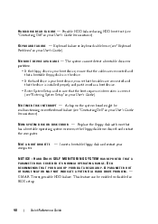
... page 269 for assistance). Possible HDD failure during HDD boot test (see "Contacting Dell" on page 269 for assistance). N O B O O T D E V I C E A V A I N T E R R U P T - N O T I M E R T I C K I L A B L E - Replace the floppy disk with one that the boot sequence information is installed properly and partitioned as a boot... cables are connected and that a bootable floppy disk is in the drive. • If the hard drive is your boot device, ensure that the cables are connected and that the drive is correct (see "Contacting Dell" on page 118). A chip on the system board might be ...
... page 269 for assistance). Possible HDD failure during HDD boot test (see "Contacting Dell" on page 269 for assistance). N O B O O T D E V I C E A V A I N T E R R U P T - N O T I M E R T I C K I L A B L E - Replace the floppy disk with one that the boot sequence information is installed properly and partitioned as a boot... cables are connected and that a bootable floppy disk is in the drive. • If the hard drive is your boot device, ensure that the cables are connected and that the drive is correct (see "Contacting Dell" on page 118). A chip on the system board might be ...

User's Guide
Page 147
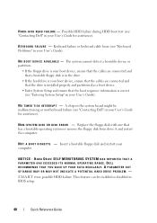
1 2 12 11 10 9 8 7 1 power supply 3 secondary hard drive bay 5 primary hard drive bay 7 processor fan 9 3.5-inch drive bay 11 5.25-inch drive bay 3 4 5 6 2 system board 4 processor airflow shroud 6 card fan 8 3.5-inch drive bay 10 5.25-inch drive bay 12 drive cage Adding and Replacing Parts 147
1 2 12 11 10 9 8 7 1 power supply 3 secondary hard drive bay 5 primary hard drive bay 7 processor fan 9 3.5-inch drive bay 11 5.25-inch drive bay 3 4 5 6 2 system board 4 processor airflow shroud 6 card fan 8 3.5-inch drive bay 10 5.25-inch drive bay 12 drive cage Adding and Replacing Parts 147
User's Guide
Page 170
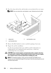
... the cover open. NOTE: The standard length for a PCI card in the last PCI slot (Slot6) is 5.5 in ) by removing the second hard drive bay bracket. 170 Adding and Replacing Parts however, you can remove the card retention cover, if desired, and set it for your computer from its electrical outlet before installing...
... the cover open. NOTE: The standard length for a PCI card in the last PCI slot (Slot6) is 5.5 in ) by removing the second hard drive bay bracket. 170 Adding and Replacing Parts however, you can remove the card retention cover, if desired, and set it for your computer from its electrical outlet before installing...

User's Guide
Page 171
Adding and Replacing Parts 171 1 2 1 screws (2) 2 second hard drive bracket 7 Place the card in the top of the card fits around the alignment guide. Ensure that the card is fully seated in the slot, the top of the card is flush with the alignment bar, and the notch in the connector and press down firmly.
Adding and Replacing Parts 171 1 2 1 screws (2) 2 second hard drive bracket 7 Place the card in the top of the card fits around the alignment guide. Ensure that the card is fully seated in the slot, the top of the card is flush with the alignment bar, and the notch in the connector and press down firmly.

User's Guide
Page 185
...; Four serial ATA (SATA) hard drives, one optical drive, and one floppy drive or one Media Card Reader • Three (SAS or SATA) hard drives, one optical drive, and one floppy drive or one Media Card Reader • One or two (SAS or SATA) hard drives with up to the connectors on... the back panel of the computer. 18 Install any drivers required for the card, as described in the card documentation. NOTE: Connect your external audio devices or your network cable to two optical drives, one floppy drive, and one Media Card Reader Adding and Replacing...
...; Four serial ATA (SATA) hard drives, one optical drive, and one floppy drive or one Media Card Reader • Three (SAS or SATA) hard drives, one optical drive, and one floppy drive or one Media Card Reader • One or two (SAS or SATA) hard drives with up to the connectors on... the back panel of the computer. 18 Install any drivers required for the card, as described in the card documentation. NOTE: Connect your external audio devices or your network cable to two optical drives, one floppy drive, and one Media Card Reader Adding and Replacing...

User's Guide
Page 186
3* 1 2 7 6 4 5 *an additional fan may be located here in computers with configurations with three SAS hard drives 1 upper 5.25-inch drive bay 2 (supports an optical drive) 3* additional fan (not shown) 4 5 primary hard drive bay 6 7 upper 3.5-inch drive bay (supports a floppy drive, a Media Card Reader, or an additional SATA or SAS hard drive) lower 5.25-inch drive bay (supports an optical drive or an additional SATA hard drive) secondary hard drive bay lower 3.5-inch drive bay (supports a floppy drive or a Media Card Reader) 186 Adding and Replacing Parts
3* 1 2 7 6 4 5 *an additional fan may be located here in computers with configurations with three SAS hard drives 1 upper 5.25-inch drive bay 2 (supports an optical drive) 3* additional fan (not shown) 4 5 primary hard drive bay 6 7 upper 3.5-inch drive bay (supports a floppy drive, a Media Card Reader, or an additional SATA or SAS hard drive) lower 5.25-inch drive bay (supports an optical drive or an additional SATA hard drive) secondary hard drive bay lower 3.5-inch drive bay (supports a floppy drive or a Media Card Reader) 186 Adding and Replacing Parts

User's Guide
Page 187
... may be located here in computers with configurations with three SAS hard drives 1 upper 5.25-inch drive bay (supports an optical drive) 3* additional fan location (not shown) 5 primary hard drive bay 2 lower 5.25-inch drive bay (supports an optical drive or an additional SATA hard drive) 4 secondary hard drive bay 6 3.5-inch drive bay (supports a floppy drive or a Media Card Reader) Adding and Replacing Parts 187
... may be located here in computers with configurations with three SAS hard drives 1 upper 5.25-inch drive bay (supports an optical drive) 3* additional fan location (not shown) 5 primary hard drive bay 2 lower 5.25-inch drive bay (supports an optical drive or an additional SATA hard drive) 4 secondary hard drive bay 6 3.5-inch drive bay (supports a floppy drive or a Media Card Reader) Adding and Replacing Parts 187

User's Guide
Page 188
... into place and its place, a shield is installed over a hard drive in the lower 5.25-inch drive bay, and you need an extra shield (see "Contacting Dell" on page 269). Removing and Replacing the Metal Shield (Upper Drive Bays) TO REMOVE A METAL SHIELD FROM AN UPPER DRIVE BAY: 1 Grasp tab located in the front-center of the...
... into place and its place, a shield is installed over a hard drive in the lower 5.25-inch drive bay, and you need an extra shield (see "Contacting Dell" on page 269). Removing and Replacing the Metal Shield (Upper Drive Bays) TO REMOVE A METAL SHIELD FROM AN UPPER DRIVE BAY: 1 Grasp tab located in the front-center of the...

User's Guide
Page 191
... may cause your computer's electronic components. Instead, place the drive on the computer. Adding and Replacing Parts 191 Removing a Hard Drive (Tower or Desktop Computer) 1 If you are removing the hard drive from the SATA0 or SATA1 connector on the system board, depending on whether you are replacing a hard drive that contains data that you want to keep, back...
... may cause your computer's electronic components. Instead, place the drive on the computer. Adding and Replacing Parts 191 Removing a Hard Drive (Tower or Desktop Computer) 1 If you are removing the hard drive from the SATA0 or SATA1 connector on the system board, depending on whether you are replacing a hard drive that contains data that you want to keep, back...

User's Guide
Page 192
b Remove the SAS connector from the SAS controller card. 192 Adding and Replacing Parts c Disconnect the SAS cable from the hard drive. 1 2 3 4 5 6 1 serial ATA cable 3 SATA1 connector 5 secondary hard drive bay 2 SATA0 connector 4 power cable 6 hard drive in primary hard drive bay To remove a SAS hard drive: a Disconnect the power cable from the SAS drive.
b Remove the SAS connector from the SAS controller card. 192 Adding and Replacing Parts c Disconnect the SAS cable from the hard drive. 1 2 3 4 5 6 1 serial ATA cable 3 SATA1 connector 5 secondary hard drive bay 2 SATA0 connector 4 power cable 6 hard drive in primary hard drive bay To remove a SAS hard drive: a Disconnect the power cable from the SAS drive.

User's Guide
Page 193
1 2 3 5 4 1 SAS connector on SAS controller 2 SAS connector on SAS controller card card 3 hard drive in secondary hard drive bay 4 hard drive in primary hard drive bay 5 blue tabs (2 on each hard drive bracket) 6 Press in on the blue tabs on each side of the hard drive bracket and slide the drive up and out of the primary or secondary hard drive bay. Adding and Replacing Parts 193
1 2 3 5 4 1 SAS connector on SAS controller 2 SAS connector on SAS controller card card 3 hard drive in secondary hard drive bay 4 hard drive in primary hard drive bay 5 blue tabs (2 on each hard drive bracket) 6 Press in on the blue tabs on each side of the hard drive bracket and slide the drive up and out of the primary or secondary hard drive bay. Adding and Replacing Parts 193


