
User Manual
Page 1
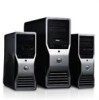
optical-drive bay 3. USB 3.0 connectors (2) 6. Front and Back View 1. headphone connector 4. USB 2.0 connectors (2) 7. optical drive Regulatory Model: D09M Regulatory Type: D09M004 2012 - 04 power button, power light 2. microphone connector 5. drive activity light 8. Front And Back View Figure 1. Dell Precision T1650 Setup And Features Information About Warnings WARNING: A WARNING indicates a potential for property damage, personal injury, or death.
optical-drive bay 3. USB 3.0 connectors (2) 6. Front and Back View 1. headphone connector 4. USB 2.0 connectors (2) 7. optical drive Regulatory Model: D09M Regulatory Type: D09M004 2012 - 04 power button, power light 2. microphone connector 5. drive activity light 8. Front And Back View Figure 1. Dell Precision T1650 Setup And Features Information About Warnings WARNING: A WARNING indicates a potential for property damage, personal injury, or death.
User Manual
Page 2
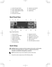
...security-cable slot 16. network link integrity light 3. For additional best practices information, see www.dell.com/regulatory_compliance. network activity light 5. line-in this section, read the safety information that shipped with your computer. power supply diagnostic button 12. USB 3.0 connectors (2) 12. Connect the monitor using only one of the procedures ... not be included if you begin any of the following cables: 2 9. line-out connector 8. USB 2.0 connectors (2) 10. network connector 4. optical-drive eject button 10. back panel connectors Back Panel View 14.
...security-cable slot 16. network link integrity light 3. For additional best practices information, see www.dell.com/regulatory_compliance. network activity light 5. line-in this section, read the safety information that shipped with your computer. power supply diagnostic button 12. USB 3.0 connectors (2) 12. Connect the monitor using only one of the procedures ... not be included if you begin any of the following cables: 2 9. line-out connector 8. USB 2.0 connectors (2) 10. network connector 4. optical-drive eject button 10. back panel connectors Back Panel View 14.

User Manual
Page 4
Press the power buttons on the monitor and the computer. The following specifications are only those required by using the power supply wattage rating. 4 4. Figure 8. Connecting Power 5. Power Voltage Wattage Input Current Coin-cell battery Maximum heat dissipation 100 VAC to 240 VAC 275 W/320 W...lithium coin cell 4774.00 BTU/hr NOTE: Heat dissipation is calculated by law to view information about your computer. Turning On Power Specifications NOTE: Offerings may vary by region. For more information regarding the configuration of your computer, click Start → Help and...
Press the power buttons on the monitor and the computer. The following specifications are only those required by using the power supply wattage rating. 4 4. Figure 8. Connecting Power 5. Power Voltage Wattage Input Current Coin-cell battery Maximum heat dissipation 100 VAC to 240 VAC 275 W/320 W...lithium coin cell 4774.00 BTU/hr NOTE: Heat dissipation is calculated by law to view information about your computer. Turning On Power Specifications NOTE: Offerings may vary by region. For more information regarding the configuration of your computer, click Start → Help and...

Owner's manual
Page 5
.... Hold a card by its pull-tab, not on a card. Disconnect your computer (see the Regulatory Compliance Homepage at www.dell.com/ regulatory_compliance CAUTION: Many repairs may appear differently than shown in your warranty. You should only perform troubleshooting and simple repairs as...1. CAUTION: To disconnect a network cable, first unplug the cable from being scratched. 2. Remove the cover. 5 Press and hold the power button while the computer is flat and clean to ensure your computer and then unplug the cable from the computer. 4. Unless otherwise noted, each ...
.... Hold a card by its pull-tab, not on a card. Disconnect your computer (see the Regulatory Compliance Homepage at www.dell.com/ regulatory_compliance CAUTION: Many repairs may appear differently than shown in your warranty. You should only perform troubleshooting and simple repairs as...1. CAUTION: To disconnect a network cable, first unplug the cable from being scratched. 2. Remove the cover. 5 Press and hold the power button while the computer is flat and clean to ensure your computer and then unplug the cable from the computer. 4. Unless otherwise noted, each ...
Owner's manual
Page 6
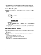
Shut down your operating system, press and hold the power button for about 6 seconds to dissipate static electricity, which could harm internal components. The computer turns off your computer. 1. If required, verify that the computer and ... programs before you connect any telephone or network cables to their electrical outlets. 4. CAUTION: Before touching anything inside your computer, ground yourself by running the Dell Diagnostics. 6 Turning Off Your Computer CAUTION: To avoid losing data, save and close all open files and exit all attached devices to your computer. 3. In...
Shut down your operating system, press and hold the power button for about 6 seconds to dissipate static electricity, which could harm internal components. The computer turns off your computer. 1. If required, verify that the computer and ... programs before you connect any telephone or network cables to their electrical outlets. 4. CAUTION: Before touching anything inside your computer, ground yourself by running the Dell Diagnostics. 6 Turning Off Your Computer CAUTION: To avoid losing data, save and close all open files and exit all attached devices to your computer. 3. In...
Owner's manual
Page 45
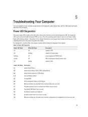
... your computer using indicators like Diagnostic Lights, Beep Codes, and Error Messages during the POST process. Amber LED blinking scheme - Power LED Diagnostics Amber LED State White LED State Description off off system is OFF off blinking system is in the middle. The diagnostic LED...Memory modules are detected, but failed to load, it is only active and visible during the operation of blinks up to 7. Power LED Diagnostics The power button LED located on the front of the chassis also functions as a bicolored diagnostic LED. Once the operating system starts to fetch code...
... your computer using indicators like Diagnostic Lights, Beep Codes, and Error Messages during the POST process. Amber LED blinking scheme - Power LED Diagnostics Amber LED State White LED State Description off off system is OFF off blinking system is in the middle. The diagnostic LED...Memory modules are detected, but failed to load, it is only active and visible during the operation of blinks up to 7. Power LED Diagnostics The power button LED located on the front of the chassis also functions as a bicolored diagnostic LED. Once the operating system starts to fetch code...

Owner's manual
Page 46
... is removed. Alert! Alert! The MFG_MODE jumper has been set of beeps, the BIOS should detect if the user presses the power button. Decreasing available memory One or more memory modules may be loose or the computer configuration information may not match the hardware configuration. ... attempts at checkpoint the same error. Bad command or file name Ensure that you have failed at booting this checkpoint and contact Dell Technical Support. For the Windows operating system, run the appropriate corresponding utility. Attachment failed to respond The floppy or hard drive ...
... is removed. Alert! Alert! The MFG_MODE jumper has been set of beeps, the BIOS should detect if the user presses the power button. Decreasing available memory One or more memory modules may be loose or the computer configuration information may not match the hardware configuration. ... attempts at checkpoint the same error. Bad command or file name Ensure that you have failed at booting this checkpoint and contact Dell Technical Support. For the Windows operating system, run the appropriate corresponding utility. Attachment failed to respond The floppy or hard drive ...

Owner's manual
Page 52
... Fan Front panel control Thermal Sensor Processor Processor Fan Service mode jumper Password clear jumper RTC reset jumper Internal speaker Intruder connector Power connector: Specification one 164-pin connector four 7-pin connectors four 240-pin connectors one 10-pin connector one 5-pin connector one... connector one 3-pin connector one 24-pin and one 4-pin connector Table 24. Controls and Lights Feature Front of the computer: Power button light Drive activity light Back of the computer. blinking white light indicates sleep state of the computer: Link integrity light on integrated ...
... Fan Front panel control Thermal Sensor Processor Processor Fan Service mode jumper Password clear jumper RTC reset jumper Internal speaker Intruder connector Power connector: Specification one 164-pin connector four 7-pin connectors four 240-pin connectors one 10-pin connector one 5-pin connector one... connector one 3-pin connector one 24-pin and one 4-pin connector Table 24. Controls and Lights Feature Front of the computer: Power button light Drive activity light Back of the computer. blinking white light indicates sleep state of the computer: Link integrity light on integrated ...

Owner's manual
Page 53
When the system power supply voltage is calculated by pressing the test button. Table 25. Environmental Feature Temperature range: Operating Storage Relative humidity (maximum): Operating Storage Maximum vibration: Operating Specification 360 mm (14.17 inches) 175... °C to 65 °C (-40 °F to 149 °F) 20% to 80% (non-condensing) 5% to the power connector (at the back of the power system by using the power supply wattage rating. Power Feature Coin-cell battery Voltage Wattage Maximum heat dissipation Specification 3 V CR2032 lithium coin cell 100 VAC to 240 VAC...
When the system power supply voltage is calculated by pressing the test button. Table 25. Environmental Feature Temperature range: Operating Storage Relative humidity (maximum): Operating Storage Maximum vibration: Operating Specification 360 mm (14.17 inches) 175... °C to 65 °C (-40 °F to 149 °F) 20% to 80% (non-condensing) 5% to the power connector (at the back of the power system by using the power supply wattage rating. Power Feature Coin-cell battery Voltage Wattage Maximum heat dissipation Specification 3 V CR2032 lithium coin cell 100 VAC to 240 VAC...

