
Connecting to PCoIP Remote Access Host Cards in Precision Host Workstations Quick Reference Guide
Page 8
... recommended) option by disregarding the message. 4. Although the Quad Display PCoIP Zero Client could be connected over the LAN to a dual display remote access host card (used in VMware environments. 4. Periodically Dell posts new versions of Teradici firmware for the remote access host cards and Wyse Zero Clients (as of December 1, 2017 comes with our workstations and will offer base level Firmware updates for bug fixes. The default password for...
... recommended) option by disregarding the message. 4. Although the Quad Display PCoIP Zero Client could be connected over the LAN to a dual display remote access host card (used in VMware environments. 4. Periodically Dell posts new versions of Teradici firmware for the remote access host cards and Wyse Zero Clients (as of December 1, 2017 comes with our workstations and will offer base level Firmware updates for bug fixes. The default password for...
Tower Owners Manual
Page 4
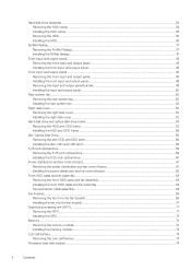
... optical drive...59 Removing the 5.25-inch optical drive...59 Installing the 5.25-inch optical drive...60 Power distribution and fan control board...61 Removing the power distribution and fan control board 61 Installing the power distribution and fan control board 62 Front HDD cable and fan assembly...63 Removing the front HDD cable and fan assembly...63 Installing the front HDD cable and fan assembly...64 Fan and sensor cable assembly...64 Fan bracket...69 Removing the fan from the fan bracket...69 Installing the fan into the fan bracket...70 Graphical...
... optical drive...59 Removing the 5.25-inch optical drive...59 Installing the 5.25-inch optical drive...60 Power distribution and fan control board...61 Removing the power distribution and fan control board 61 Installing the power distribution and fan control board 62 Front HDD cable and fan assembly...63 Removing the front HDD cable and fan assembly...63 Installing the front HDD cable and fan assembly...64 Fan and sensor cable assembly...64 Fan bracket...69 Removing the fan from the fan bracket...69 Installing the fan into the fan bracket...70 Graphical...
Tower Owners Manual
Page 5
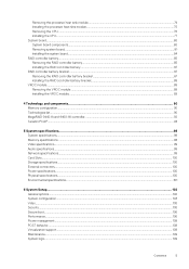
...-16i controller...92 Teradici PCoIP...94 5 System specifications...98 System specifications...98 Memory specifications ...98 Video specifications...99 Audio specifications...99 Network specifications...99 Card Slots...100 Storage specifications...100 External connectors...100 Power specifications...100 Physical specifications...100 Environmental specifications...101 6 System Setup...102 General options...102 System configuration...103 Video...105 Security...105 Secure boot...106 Performance...106 Power management...108 POST behavior...108 Virtualization support...109 Maintenance...109 System...
...-16i controller...92 Teradici PCoIP...94 5 System specifications...98 System specifications...98 Memory specifications ...98 Video specifications...99 Audio specifications...99 Network specifications...99 Card Slots...100 Storage specifications...100 External connectors...100 Power specifications...100 Physical specifications...100 Environmental specifications...101 6 System Setup...102 General options...102 System configuration...103 Video...105 Security...105 Secure boot...106 Performance...106 Power management...108 POST behavior...108 Virtualization support...109 Maintenance...109 System...

Tower Owners Manual
Page 6
...ePSA Diagnostic 3.0 121 Running the ePSA Diagnostics...121 Testing memory using a USB flash drive 110 Updating the Dell BIOS in Windows ...110 Updating BIOS on systems with BitLocker enabled 110 Updating your system BIOS using ePSA...121 Preboot blinking power button codes...122 Hard drive indicator codes...125 9 Contacting Dell...127 6 Contents Engineering configurations...109 Updating the BIOS in Linux and Ubuntu environments 111 Flashing the BIOS from the F12 One-Time boot menu 111 MegaRAID controller options...114 System and setup password...115 Assigning a system setup password...
...ePSA Diagnostic 3.0 121 Running the ePSA Diagnostics...121 Testing memory using a USB flash drive 110 Updating the Dell BIOS in Windows ...110 Updating BIOS on systems with BitLocker enabled 110 Updating your system BIOS using ePSA...121 Preboot blinking power button codes...122 Hard drive indicator codes...125 9 Contacting Dell...127 6 Contents Engineering configurations...109 Updating the BIOS in Linux and Ubuntu environments 111 Flashing the BIOS from the F12 One-Time boot menu 111 MegaRAID controller options...114 System and setup password...115 Assigning a system setup password...
Tower Owners Manual
Page 14
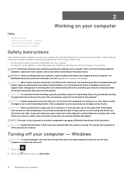
.... if you finish working inside the computer, replace all power sources before opening the computer cover or panels. Also, before connecting to ensure your warranty. NOTE: The color of your computer. After you are removed while the system is running. You should only perform troubleshooting and simple repairs as a processor by its edges, not by the online or telephone service and support team. Hold a component...
.... if you finish working inside the computer, replace all power sources before opening the computer cover or panels. Also, before connecting to ensure your warranty. NOTE: The color of your computer. After you are removed while the system is running. You should only perform troubleshooting and simple repairs as a processor by its edges, not by the online or telephone service and support team. Hold a component...
Tower Owners Manual
Page 15
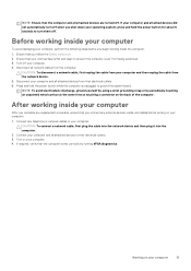
... working inside your computer To avoid damaging your computer 15 Turn off when you shut down your computer After you complete any replacement procedure, ensure that you follow the Safety Instruction. 2. Connect any external devices, cards, and cables before you begin working inside the computer. 1. NOTE: Ensure that the computer and all network cables from the computer. After working inside your operating system, press and hold the power button...
... working inside your computer To avoid damaging your computer 15 Turn off when you shut down your computer After you complete any replacement procedure, ensure that you follow the Safety Instruction. 2. Connect any external devices, cards, and cables before you begin working inside the computer. 1. NOTE: Ensure that the computer and all network cables from the computer. After working inside your operating system, press and hold the power button...

Tower Owners Manual
Page 16
... bezel • Front input and output panel • Rear system fan • Right side cover • Hard disk drive and optical disk drive frame • Slim Optical Disk Drive • 5.25-inch optical drive • Power distribution and fan control board • Front HDD cable and fan assembly • Fan bracket • Graphical processing unit(GPU) • Memory • Coin cell battery • Processor heat sink module • System board • RAID controller battery • RAID controller battery bracket • VROC module Screw size...
... bezel • Front input and output panel • Rear system fan • Right side cover • Hard disk drive and optical disk drive frame • Slim Optical Disk Drive • 5.25-inch optical drive • Power distribution and fan control board • Front HDD cable and fan assembly • Fan bracket • Graphical processing unit(GPU) • Memory • Coin cell battery • Processor heat sink module • System board • RAID controller battery • RAID controller battery bracket • VROC module Screw size...

Tower Owners Manual
Page 69
... HDD# FAN is installed, the HDD fans can be verified in Before working . Fan bracket Removing the fan from the fan chassis [1]. To remove the fan from the fan bracket: a) Slide out the four rubber grommets for each fan from the fan bracket 1. Remove the: a) side cover b) system fan 3. b) Lift the fan and remove it needs to verify if all the fans are encouraged to run ePSA after the service is completed to manually unchecked...
... HDD# FAN is installed, the HDD fans can be verified in Before working . Fan bracket Removing the fan from the fan chassis [1]. To remove the fan from the fan bracket: a) Slide out the four rubber grommets for each fan from the fan bracket 1. Remove the: a) side cover b) system fan 3. b) Lift the fan and remove it needs to verify if all the fans are encouraged to run ePSA after the service is completed to manually unchecked...

Tower Owners Manual
Page 92
... Adapter is a 12Gb/s SAS/SATA/PCIe (NVMe) controller card that addresses these controllers provide bandwidth and IOPS performance increases and are only supported when using Intel Xeon W Series CPUs. Tri-Mode support provides a non-disruptive way to seamlessly work with any of the three types of storage devices. By upgrading to a tri-mode controller, users can be operated by providing connectivity and data protection for high-end servers utilizing internal storage or connecting...
... Adapter is a 12Gb/s SAS/SATA/PCIe (NVMe) controller card that addresses these controllers provide bandwidth and IOPS performance increases and are only supported when using Intel Xeon W Series CPUs. Tri-Mode support provides a non-disruptive way to seamlessly work with any of the three types of storage devices. By upgrading to a tri-mode controller, users can be operated by providing connectivity and data protection for high-end servers utilizing internal storage or connecting...

Tower Owners Manual
Page 95
... and Host Card, make sure the power management cable on the Teradici card is connected properly on the host PC. To keep this step. The power management cable from Teradici Corporation. 10. If prompted, restart the operating system; Click Install to continue. 11. Refer the below image for the operating system installed on the system board. 5. Power management cable configuration for Teradici PCoIP Portal and Host Card If the Dell Precision Workstation comes...
... and Host Card, make sure the power management cable on the Teradici card is connected properly on the host PC. To keep this step. The power management cable from Teradici Corporation. 10. If prompted, restart the operating system; Click Install to continue. 11. Refer the below image for the operating system installed on the system board. 5. Power management cable configuration for Teradici PCoIP Portal and Host Card If the Dell Precision Workstation comes...

Tower Owners Manual
Page 100
...SATA/SAS Drives with optional controller External connectors Features Audio Network Serial port USB PS2 Specifications • Rear-1 x Audio Line out • Rear-1 x Audio Line in/Microphone • Front-1 x Universal Audio Jack Rear-2 x RJ45 Network ports Rear-1 x Serial port • Front-2 x USB 3.1 Gen 1 and 2 x USB 3.1 Gen 1 Type-C (1 with 2nd CPU) • one PCIE Gen 3 x8 (open ended connector) • one PCIE Gen 3 x16 (wired as x4) • one PCIE Gen 3 x16 (wired as x1) Storage specifications Features Externally Accessible Internally Accessible Specifications DVD-ROM; DVD...
...SATA/SAS Drives with optional controller External connectors Features Audio Network Serial port USB PS2 Specifications • Rear-1 x Audio Line out • Rear-1 x Audio Line in/Microphone • Front-1 x Universal Audio Jack Rear-2 x RJ45 Network ports Rear-1 x Serial port • Front-2 x USB 3.1 Gen 1 and 2 x USB 3.1 Gen 1 Type-C (1 with 2nd CPU) • one PCIE Gen 3 x8 (open ended connector) • one PCIE Gen 3 x16 (wired as x4) • one PCIE Gen 3 x16 (wired as x1) Storage specifications Features Externally Accessible Internally Accessible Specifications DVD-ROM; DVD...
Tower Owners Manual
Page 103
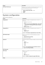
... HDD-Default • Always • Never Description Allows you to use the Disabled option, only if Active Management Technology (AMT) option is disabled. • Enabled • Enabled w/PXE (Default) Allows you to support RAID mode. The options are : • Disabled • AHCI • RAID-On (Default) NOTE: SATA is set the serial port to configure the internal SATA hard-drive controller. Identifies and defines the serial port settings. Allows pre-OS and early OS networking features to configure the integrated network controller. System Setup 103 Option UEFI Boot...
... HDD-Default • Always • Never Description Allows you to use the Disabled option, only if Active Management Technology (AMT) option is disabled. • Enabled • Enabled w/PXE (Default) Allows you to support RAID mode. The options are : • Disabled • AHCI • RAID-On (Default) NOTE: SATA is set the serial port to configure the internal SATA hard-drive controller. Identifies and defines the serial port settings. Allows pre-OS and early OS networking features to configure the integrated network controller. System Setup 103 Option UEFI Boot...

Tower Owners Manual
Page 104
... (SD) Card Boot Allows you to enable or disable Thunderbolt device support capability. • Enabled • Disabled (Default) Allows you to enable or disable the internal USB configuration. NOTE: If the hard drives are : • Enable Boot Support • Enable Front USB Ports • Enable internal USB ports • Enable rear USB Ports Allows you to a RAID controller card, the hard drives will display {none} in the RAID controller card BIOS. Option 7920 Tower PCIe Drives SMART Reporting USB Configuration HDD Fans Audio Memory Map IO above 4GB - The hard drives can be...
... (SD) Card Boot Allows you to enable or disable Thunderbolt device support capability. • Enabled • Disabled (Default) Allows you to enable or disable the internal USB configuration. NOTE: If the hard drives are : • Enable Boot Support • Enable Front USB Ports • Enable internal USB ports • Enable rear USB Ports Allows you to a RAID controller card, the hard drives will display {none} in the RAID controller card BIOS. Option 7920 Tower PCIe Drives SMART Reporting USB Configuration HDD Fans Audio Memory Map IO above 4GB - The hard drives can be...

Tower Owners Manual
Page 110
... your computer model and the Product Support page of your BIOS (System Setup), when you reboot the system it to install the updated BIOS settings on your computer. 12. Click Run to a bootable USB Flash Drive. Updating BIOS on screen. 3. Please refer to Dell.com/support. • Enter the Service Tag or Express Service Code and click Submit. • Click Detect Product and follow the instructions on systems with BitLocker enabled CAUTION: If BitLocker...
... your computer model and the Product Support page of your BIOS (System Setup), when you reboot the system it to install the updated BIOS settings on your computer. 12. Click Run to a bootable USB Flash Drive. Updating BIOS on screen. 3. Please refer to Dell.com/support. • Enter the Service Tag or Express Service Code and click Submit. • Click Detect Product and follow the instructions on systems with BitLocker enabled CAUTION: If BitLocker...
Tower Owners Manual
Page 114
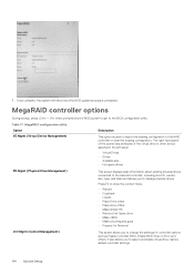
... the BIOS update process is used to import the existing configuration to the RAID controller or clear the existing configuration. MegaRAID configuration utility Option VD Mgmt (Virtual Device Management) Description This option is completed. Table 17. 7. It also allows you to select a bootable virtual drive, restore default controller settings. 114 System Setup MegaRAID controller options During bootup, press + when prompted by the BIOS screen to get to manage physical drives. Press F2 to show the context menu...
... the BIOS update process is used to import the existing configuration to the RAID controller or clear the existing configuration. MegaRAID configuration utility Option VD Mgmt (Virtual Device Management) Description This option is completed. Table 17. 7. It also allows you to select a bootable virtual drive, restore default controller settings. 114 System Setup MegaRAID controller options During bootup, press + when prompted by the BIOS screen to get to manage physical drives. Press F2 to show the context menu...

Tower Owners Manual
Page 117
... driver file. 9. Click Download File to install. 7. Turn on the computer. 2. After the download is complete, navigate to the folder where you do not have the Service Tag, use the auto detect feature or manually browse for your system, and then click Submit. Topics: • Supported operating systems • Downloading drivers • Chipset driver • Graphics controller driver • USB drivers • Network drivers • Audio drivers • Ports • Storage controller drivers • Other drivers Supported operating...
... driver file. 9. Click Download File to install. 7. Turn on the computer. 2. After the download is complete, navigate to the folder where you do not have the Service Tag, use the auto detect feature or manually browse for your system, and then click Submit. Topics: • Supported operating systems • Downloading drivers • Chipset driver • Graphics controller driver • USB drivers • Network drivers • Audio drivers • Ports • Storage controller drivers • Other drivers Supported operating...

Tower Owners Manual
Page 122
... troubleshoot, narrow down the issue by ensuring CPU 0 is installed, CPU0 and CPU1 is an idendical matching pair and swapping a known good CPUs if available. • If nothing works, contact Tech Support 2-1 2 amber blinks followed by a Bad Processor • CPU configuration activity is short pause, 1 white blink, long in Recovery short pause, 2 white blinks, long Mode. Preboot blinking power button codes Table 20. Power button LED state Power Button LED State Off Blinking Amber Blinking...
... troubleshoot, narrow down the issue by ensuring CPU 0 is installed, CPU0 and CPU1 is an idendical matching pair and swapping a known good CPUs if available. • If nothing works, contact Tech Support 2-1 2 amber blinks followed by a Bad Processor • CPU configuration activity is short pause, 1 white blink, long in Recovery short pause, 2 white blinks, long Mode. Preboot blinking power button codes Table 20. Power button LED state Power Button LED State Off Blinking Amber Blinking...

Tower Owners Manual
Page 123
... can assist to troubleshoot, narrow down the issue by removing the memory module one by one to troubleshoot, narrow down the issue by a PCI Device or Video short pause, 2 white blinks, long pause, then repeats Suggested Resolution • Flash latest BIOS version. If problem persists, contact Tech Support • If customer can assist to troubleshoot, narrow down the issue by removing the memory module one...
... can assist to troubleshoot, narrow down the issue by removing the memory module one by one to troubleshoot, narrow down the issue by a PCI Device or Video short pause, 2 white blinks, long pause, then repeats Suggested Resolution • Flash latest BIOS version. If problem persists, contact Tech Support • If customer can assist to troubleshoot, narrow down the issue by removing the memory module one...

Tower VGA dongle Installation Guide
Page 4
... computer. WARNING: Before working inside the computer, replace all network cables from their electrical outlets. 5 Open the display. 6 Press and hold the power button for few seconds, to ensure your computer and certain components may only be replaced or, if purchased separately, installed by a certified service technician. Hold a card by its edges or by its pins. Hold a component such as touching a connector on the back...
... computer. WARNING: Before working inside the computer, replace all network cables from their electrical outlets. 5 Open the display. 6 Press and hold the power button for few seconds, to ensure your computer and certain components may only be replaced or, if purchased separately, installed by a certified service technician. Hold a card by its edges or by its pins. Hold a component such as touching a connector on the back...
Tower VGA dongle Installation Guide
Page 5
... or "walking wounded") failure. An example of semiconductors used in previous Dell products. When connecting a bonding wire, ensure that has received a static shock and immediately generates a "No POST/No Video" symptom with standby power must be taken before performing any installed ExpressCards or Smart Cards from the system. • Use an ESD field service kit when working inside any desktop to bonding yourself and...
... or "walking wounded") failure. An example of semiconductors used in previous Dell products. When connecting a bonding wire, ensure that has received a static shock and immediately generates a "No POST/No Video" symptom with standby power must be taken before performing any installed ExpressCards or Smart Cards from the system. • Use an ESD field service kit when working inside any desktop to bonding yourself and...


