Quick Reference Guide
Page 7
... • Downloads - system • Customer Care - Computer documentation, details on the screen. Troubleshooting hints and tips, articles Dell Support Website - Contact information, service call status and support history, service contract, online discussions with programs and files • Documentation...reinstall the operating system for devices (such as memory, the hard drive, and the operating premier.support.dell.com. support.dell.com from technicians, and online courses, frequently asked NOTE: Select your Dell computer. The website may not be available ...
... • Downloads - system • Customer Care - Computer documentation, details on the screen. Troubleshooting hints and tips, articles Dell Support Website - Contact information, service call status and support history, service contract, online discussions with programs and files • Documentation...reinstall the operating system for devices (such as memory, the hard drive, and the operating premier.support.dell.com. support.dell.com from technicians, and online courses, frequently asked NOTE: Select your Dell computer. The website may not be available ...
Quick Reference Guide
Page 17
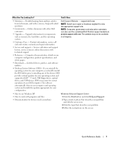
... problems with your computer. 10 microphone connector Use the microphone connector to attach a personal computer microphone for devices that you connect occasionally, such as flash memory keys, cameras, or bootable USB devices (see your User's Guide. See your User's Guide for more information). The computer is in a power-saving state. •...
... problems with your computer. 10 microphone connector Use the microphone connector to attach a personal computer microphone for devices that you connect occasionally, such as flash memory keys, cameras, or bootable USB devices (see your User's Guide. See your User's Guide for more information). The computer is in a power-saving state. •...

Quick Reference Guide
Page 19
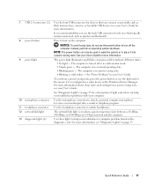
... connect a mouse to attach headphones and most speakers with a sound card, use the front USB connectors for devices that you connect occasionally, such as flash memory keys, cameras, or bootable USB devices.
... connect a mouse to attach headphones and most speakers with a sound card, use the front USB connectors for devices that you connect occasionally, such as flash memory keys, cameras, or bootable USB devices.

Quick Reference Guide
Page 20
... cameras and external storage devices. and extranet). If you connect occasionally, such as a handheld device, to the serial port. Connect a serial device, such as flash memory keys, cameras, or bootable USB devices. Use the IEEE 1394 connector for devices that typically remain connected, such as a separate intra- A good connection exists between...
... cameras and external storage devices. and extranet). If you connect occasionally, such as a handheld device, to the serial port. Connect a serial device, such as flash memory keys, cameras, or bootable USB devices. Use the IEEE 1394 connector for devices that typically remain connected, such as a separate intra- A good connection exists between...
Quick Reference Guide
Page 21
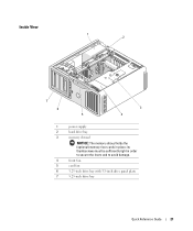
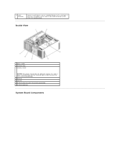
Inside View 1 2 7 6 1 2 3 4 5 6 7 3 5 4 power supply hard drive bay memory shroud NOTICE: The memory shroud holds the (optional) memory riser cards in order to secure the risers and to avoid damage. front fan card fan 5.25-inch drive bay with 3.5-inch drive panel plate 5.25-inch drive bay Quick Reference Guide 21 its thumbscrews must be sufficiently tight in place;
Inside View 1 2 7 6 1 2 3 4 5 6 7 3 5 4 power supply hard drive bay memory shroud NOTICE: The memory shroud holds the (optional) memory riser cards in order to secure the risers and to avoid damage. front fan card fan 5.25-inch drive bay with 3.5-inch drive panel plate 5.25-inch drive bay Quick Reference Guide 21 its thumbscrews must be sufficiently tight in place;

Quick Reference Guide
Page 23
... is replaced by a x16 slot on the graphics riser. It holds a graphics card. 30 memory fan connector (FAN_MEM) 31 white memory module connectors (DIMM_1-4) support memory modules or memory module risers 32 black memory module connectors (DIMM_5-8) support memory modules only when no memory riser cards are installed; 1 secondary processor connector (CPU_1) 2 front fan connector (FAN_FRONT) 3 card...
... is replaced by a x16 slot on the graphics riser. It holds a graphics card. 30 memory fan connector (FAN_MEM) 31 white memory module connectors (DIMM_1-4) support memory modules or memory module risers 32 black memory module connectors (DIMM_5-8) support memory modules only when no memory riser cards are installed; 1 secondary processor connector (CPU_1) 2 front fan connector (FAN_FRONT) 3 card...

Quick Reference Guide
Page 24
... in the Product Information Guide. Seek assistance before removing the cover. See your computer from your hard drive or the Dell Support website at all of the available connectors • Inside views of your computer, including a detailed graphic of the...XP operating system • Instructions for removing and installing parts, including memory, cards, drives, the microprocessor, and the battery • Information for troubleshooting various computer problems • Instructions for using the Dell Diagnostics and reinstalling drivers • Information on software features, such as...
... in the Product Information Guide. Seek assistance before removing the cover. See your computer from your hard drive or the Dell Support website at all of the available connectors • Inside views of your computer, including a detailed graphic of the...XP operating system • Instructions for removing and installing parts, including memory, cards, drives, the microprocessor, and the battery • Information for troubleshooting various computer problems • Instructions for using the Dell Diagnostics and reinstalling drivers • Information on software features, such as...
Quick Reference Guide
Page 33
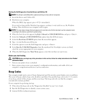
... your printer if one is optional and may not ship with all of your User's Guide. 2 Run the Dell Diagnostics to identify a more serious cause. 3 Contact Dell for technical assistance. This beep code tells you see the Windows desktop. If your computer beeps during start -up...the Boot from CD-ROM option from the numbered list. Before you start the Dell Diagnostics and press . 8 Select Run the 32 Bit Dell Diagnostics from the menu that the computer encountered a memory problem. Starting the Dell Diagnostics From the Drivers and Utilities CD NOTE: The Drivers and Utilities CD is...
... your printer if one is optional and may not ship with all of your User's Guide. 2 Run the Dell Diagnostics to identify a more serious cause. 3 Contact Dell for technical assistance. This beep code tells you see the Windows desktop. If your computer beeps during start -up...the Boot from CD-ROM option from the numbered list. Before you start the Dell Diagnostics and press . 8 Select Run the 32 Bit Dell Diagnostics from the menu that the computer encountered a memory problem. Starting the Dell Diagnostics From the Drivers and Utilities CD NOTE: The Drivers and Utilities CD is...

Quick Reference Guide
Page 34
...checksum failure Programmable interval timer failure DMA initialization failure DMA page register read/write failure Video Memory Test failure Memory not being properly identified or used Memory problem Slave DMA register failure Master DMA register failure Master interrupt mask register failure Slave ...interrupt mask register failure Interrupt vector loading failure Keyboard Controller Test failure NVRAM power loss Invalid NVRAM configuration Video Memory Test failure Screen initialization failure Screen retrace failure Search for video ROM failure No timer tick Shutdown failure Gate ...
...checksum failure Programmable interval timer failure DMA initialization failure DMA page register read/write failure Video Memory Test failure Memory not being properly identified or used Memory problem Slave DMA register failure Master DMA register failure Master interrupt mask register failure Slave ...interrupt mask register failure Interrupt vector loading failure Keyboard Controller Test failure NVRAM power loss Invalid NVRAM configuration Video Memory Test failure Screen initialization failure Screen retrace failure Search for video ROM failure No timer tick Shutdown failure Gate ...
Quick Reference Guide
Page 36
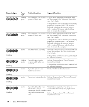
... failure has been Verify that the processor is seated correctly and restart the computer. Perform the procedure in "Power Problems" in connected to the memory and graphics riser component such as a graphics cards. See "Advanced Features" in your User's Guide. 36 Quick Reference Guide Ensure that any... one of the appropriate methods to "wake power or "sleep" state. up " the computer. amber A processor mismatch exists. riser card or memory riser card. The computer is still not resolved, contact Dell for technical assistance. See "Processor" in your User's Guide.
... failure has been Verify that the processor is seated correctly and restart the computer. Perform the procedure in "Power Problems" in connected to the memory and graphics riser component such as a graphics cards. See "Advanced Features" in your User's Guide. 36 Quick Reference Guide Ensure that any... one of the appropriate methods to "wake power or "sleep" state. up " the computer. amber A processor mismatch exists. riser card or memory riser card. The computer is still not resolved, contact Dell for technical assistance. See "Processor" in your User's Guide.

Quick Reference Guide
Page 39
Light Pattern Problem Description No memory modules are not defective. 8 When the defective memory module is identified, contact Dell for more information. 7 If the memory module passes, shut down the computer, remove the memory module, and then repeat the process with reduced performance and reduced ...capability 5 Press to boot to the operating system. 6 Run the Dell Diagnostics. See your User's Guide for a replacement. Suggested Resolution 1 Reseat the memory modules to ensure that your memory is defective, repeat the process with the remaining modules to ensure that...
Light Pattern Problem Description No memory modules are not defective. 8 When the defective memory module is identified, contact Dell for more information. 7 If the memory module passes, shut down the computer, remove the memory module, and then repeat the process with reduced performance and reduced ...capability 5 Press to boot to the operating system. 6 Run the Dell Diagnostics. See your User's Guide for a replacement. Suggested Resolution 1 Reseat the memory modules to ensure that your memory is defective, repeat the process with the remaining modules to ensure that...

Quick Reference Guide
Page 40
... module or reinstalled all modules without error. • If available, install properly working memory of the same type into your computer. • If the problem persists, contact Dell. If the computer starts normally, reinstall an additional module. Contact Dell for on-screen initialization. Continue until you are installing are compatible with your monitor...
... module or reinstalled all modules without error. • If available, install properly working memory of the same type into your computer. • If the problem persists, contact Dell. If the computer starts normally, reinstall an additional module. Contact Dell for on-screen initialization. Continue until you are installing are compatible with your monitor...
User Guide
Page 1
..., Xeon, and Celeron are trademarks of your computer. under license; Dell Inc. Dell Precision™ Workstation 690 User's Guide Information About Your Computer About Your Computer Advanced Features Copying CDs and DVDs Before You Begin Computer Stand Removing the Computer Cover Chassis Intrusion Switch Memory Drives Cards Installing the Speaker (Optional) Processor Battery I/O Panel System...
..., Xeon, and Celeron are trademarks of your computer. under license; Dell Inc. Dell Precision™ Workstation 690 User's Guide Information About Your Computer About Your Computer Advanced Features Copying CDs and DVDs Before You Begin Computer Stand Removing the Computer Cover Chassis Intrusion Switch Memory Drives Cards Installing the Speaker (Optional) Processor Battery I/O Panel System...
User Guide
Page 2
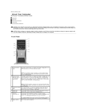
...front USB connectors for devices that typically remain connected, such as printers and keyboards. it can be on when a device such as flash memory keys, cameras, or bootable USB devices (see Drive Panels. Press to avoid injury; this computer requires a two-man lift. The floppy-... a floppy drive or Media Card Reader; The light might also be difficult to maneuver. Back to Contents Page About Your Computer Dell Precision™ Workstation 690 User's Guide Front View Back View Back Panel Connectors Inside View System Board Components CAUTION: Your computer is heavy (it ; For...
...front USB connectors for devices that typically remain connected, such as printers and keyboards. it can be on when a device such as flash memory keys, cameras, or bootable USB devices (see Drive Panels. Press to avoid injury; this computer requires a two-man lift. The floppy-... a floppy drive or Media Card Reader; The light might also be difficult to maneuver. Back to Contents Page About Your Computer Dell Precision™ Workstation 690 User's Guide Front View Back View Back Panel Connectors Inside View System Board Components CAUTION: Your computer is heavy (it ; For...

User Guide
Page 4
...USB keyboard, plug it into the purple keyboard connector. Use the back USB connectors for devices that you connect occasionally, such as flash memory keys, cameras, or bootable USB devices. On computers with a sound card, use the connector on your computer is transmitting or receiving ...Orange - A good connection exists between a 10-Mbps network and the computer. A click indicates that typically remain connected, such as flash memory keys, cameras, or bootable USB devices. If necessary, the address for high-speed data devices such as printers and keyboards. 9 IEEE 1394...
...USB keyboard, plug it into the purple keyboard connector. Use the back USB connectors for devices that you connect occasionally, such as flash memory keys, cameras, or bootable USB devices. On computers with a sound card, use the connector on your computer is transmitting or receiving ...Orange - A good connection exists between a 10-Mbps network and the computer. A click indicates that typically remain connected, such as flash memory keys, cameras, or bootable USB devices. If necessary, the address for high-speed data devices such as printers and keyboards. 9 IEEE 1394...
User Guide
Page 5
Inside View 1 power supply 2 hard drive bay 3 memory shroud NOTICE: The memory shroud holds the (optional) memory riser cards in order to secure the risers and to the serial port. If necessary, the address for this port can be sufficiently tight in place; 13 serial connector Connect a serial device, such as a handheld device, to avoid damage. 4 front fan 5 card fan 6 5.25-inch drive bay with 3.5-inch drive panel plate 7 5.25-inch drive bay System Board Components its thumbscrews must be modified through system setup (see System Setup).
Inside View 1 power supply 2 hard drive bay 3 memory shroud NOTICE: The memory shroud holds the (optional) memory riser cards in order to secure the risers and to the serial port. If necessary, the address for this port can be sufficiently tight in place; 13 serial connector Connect a serial device, such as a handheld device, to avoid damage. 4 front fan 5 card fan 6 5.25-inch drive bay with 3.5-inch drive panel plate 7 5.25-inch drive bay System Board Components its thumbscrews must be modified through system setup (see System Setup).

User Guide
Page 7
...) Floppy drive CD/DVD drive Color blue cable black pull-tab orange pull-tab Back to Contents Page It holds a graphics card. 31 memory fan connector (FAN_MEM) 32 white memory module connectors (DIMM_14) support memory modules or memory module risers 33 black memory module connectors (DIMM_5-8) support memory modules only when no memory riser cards are installed;
...) Floppy drive CD/DVD drive Color blue cable black pull-tab orange pull-tab Back to Contents Page It holds a graphics card. 31 memory fan connector (FAN_MEM) 32 white memory module connectors (DIMM_14) support memory modules or memory module risers 33 black memory module connectors (DIMM_5-8) support memory modules only when no memory riser cards are installed;

User Guide
Page 13
...watch for your computer l To set or change the settings for it is displayed for future reference. Entering System Setup 1. When the blue DELL™ logo is displayed, you add, change, or remove any settings. Once this keystroke will be lost. 4. This prompt can make your...before you are an expert computer user, do not change a user-selectable option such as the user password l To read the current amount of memory or set , you are prompted, this F2 prompt appears, press immediately. Type your computer. 2. Confirm that the keyboard has initialized. Exit ...
...watch for your computer l To set or change the settings for it is displayed for future reference. Entering System Setup 1. When the blue DELL™ logo is displayed, you add, change, or remove any settings. Once this keystroke will be lost. 4. This prompt can make your...before you are an expert computer user, do not change a user-selectable option such as the user password l To read the current amount of memory or set , you are prompted, this F2 prompt appears, press immediately. Type your computer. 2. Confirm that the keyboard has initialized. Exit ...

User Guide
Page 14
... PXE. Internal enables the internal floppy drive. Displays the amount of Installed Memory, Memory Speed, Memory Channel Mode, and a description of each PCI, PCI Express, and PCI-X slot. Displays the contents of the Memory Technology. Drives 3 through 2 (On default) NOTE: Operating systems with USB... drive. Drives 0 through 4 (On default) Enables or disables a PATA device (such as listed. System System Info Processor Info Memory Info PCI Info Date/Time Boot Sequence Displays the Computer name, BIOS Version number, BIOS Date, Service Tag, Express Service Code, and...
... PXE. Internal enables the internal floppy drive. Displays the amount of Installed Memory, Memory Speed, Memory Channel Mode, and a description of each PCI, PCI Express, and PCI-X slot. Displays the contents of the Memory Technology. Drives 3 through 2 (On default) NOTE: Operating systems with USB... drive. Drives 0 through 4 (On default) Enables or disables a PATA device (such as listed. System System Info Processor Info Memory Info PCI Info Date/Time Boot Sequence Displays the Computer name, BIOS Version number, BIOS Date, Service Tag, Express Service Code, and...

User Guide
Page 16
... enabled, this feature. Enables or disables the Trusted Platform Module security device. (Off default) Execute Disable Enables or disables Execute Disable memory protection technology. (On default) Power Management AC Recovery (Off default) Determines how the system responds when AC power is enabled, the...allows the user access to modify system setup settings. Maintenance Service Tag Displays the service tag for many components, however, system memory remains active. Change the startup time by pressing the right- Enter the administrator password at the time set in the Power ...
... enabled, this feature. Enables or disables the Trusted Platform Module security device. (Off default) Execute Disable Enables or disables Execute Disable memory protection technology. (On default) Power Management AC Recovery (Off default) Determines how the system responds when AC power is enabled, the...allows the user access to modify system setup settings. Maintenance Service Tag Displays the service tag for many components, however, system memory remains active. Change the startup time by pressing the right- Enter the administrator password at the time set in the Power ...


