
Service Manual
Page 9
... is incorrectly installed. Disconnect your computer and devices from its electrical outlet. Before disconnecting a peripheral device from the computer, wait 10 to dissipate any static electricity that might harm internal components. Before removing a component from your body before touching anything inside your ...the system board has turned off the computer and any telephone or network lines from potential damage and to ensure your online Dell documentation or otherwise provided to help protect your computer system from the computer. While you . To locate this light, see ...
... is incorrectly installed. Disconnect your computer and devices from its electrical outlet. Before disconnecting a peripheral device from the computer, wait 10 to dissipate any static electricity that might harm internal components. Before removing a component from your body before touching anything inside your ...the system board has turned off the computer and any telephone or network lines from potential damage and to ensure your online Dell documentation or otherwise provided to help protect your computer system from the computer. While you . To locate this light, see ...

Service Manual
Page 10
As you periodically review the safety instructions in on its pins. In addition, Dell recommends that you pull connectors apart, keep them evenly aligned to avoid bending any telephone or telecommunication lines from the computer. Hold a component such as a ... its connector or on the locking tabs before disconnecting the cable. Hold a card by its edges or by its strainrelief loop, not on a card. www.dell.com | support.dell.com Also, disconnect any connector pins. In addition, take note of cable, press in your Setup and Quick Reference Guide...
As you periodically review the safety instructions in on its pins. In addition, Dell recommends that you pull connectors apart, keep them evenly aligned to avoid bending any telephone or telecommunication lines from the computer. Hold a component such as a ... its connector or on the locking tabs before disconnecting the cable. Hold a card by its edges or by its strainrelief loop, not on a card. www.dell.com | support.dell.com Also, disconnect any connector pins. In addition, take note of cable, press in your Setup and Quick Reference Guide...

Service Manual
Page 15
... computer on the system board has turned off the computer and devices, disconnect them from their electrical outlets, and wait 10 to 20 seconds after disconnecting the computer from the computer, wait 10 to 20 seconds. 2 If you perform this light, see "System Board Components." 1 Turn off . Before removing a component from the...
... computer on the system board has turned off the computer and devices, disconnect them from their electrical outlets, and wait 10 to 20 seconds after disconnecting the computer from the computer, wait 10 to 20 seconds. 2 If you perform this light, see "System Board Components." 1 Turn off . Before removing a component from the...

Service Manual
Page 31
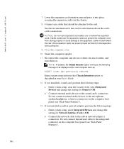
Front Panel • Removing the front panel • Replacing the front panel Removing the Front Panel CAUTION: Before you perform this procedure, see the following figure). 31 For You and Your Computer." 1 Turn off the computer and devices, disconnect them from their electrical outlets, wait at least 10 to 20 seconds, lay the computer on its right side, and open the computer cover. 2 Disconnect and remove all disk drives from the chassis drive bay. 3 Release the front panel by pressing each of the seven front-panel release buttons (see "Safety First-
Front Panel • Removing the front panel • Replacing the front panel Removing the Front Panel CAUTION: Before you perform this procedure, see the following figure). 31 For You and Your Computer." 1 Turn off the computer and devices, disconnect them from their electrical outlets, wait at least 10 to 20 seconds, lay the computer on its right side, and open the computer cover. 2 Disconnect and remove all disk drives from the chassis drive bay. 3 Release the front panel by pressing each of the seven front-panel release buttons (see "Safety First-

Service Manual
Page 33
... the front panel to use. For You and Your Computer." 1 Turn off the computer and devices, disconnect them from their electrical outlets, wait at least 10 to 20 seconds, lay the computer on its right side, and open the computer cover. 2 Disconnect and remove any disk drives from the chassis drive...
... the front panel to use. For You and Your Computer." 1 Turn off the computer and devices, disconnect them from their electrical outlets, wait at least 10 to 20 seconds, lay the computer on its right side, and open the computer cover. 2 Disconnect and remove any disk drives from the chassis drive...

Service Manual
Page 35
When these clips are released, the button comes free from their electrical outlets, wait at least 10 to 20 seconds, lay the computer on its right side, and open the computer cover. 2 Remove the front panel. 3 Lay the front panel down with the inside of the panel facing up. 4 Use a small screwdriver to push in the two plastic clips that secure the power button to the computer cover. Front-Panel Button • Removing the front-panel button • Replacing the front-panel button Removing the Front-Panel Button 1 Turn off the computer and devices, disconnect them from the front panel. 35
When these clips are released, the button comes free from their electrical outlets, wait at least 10 to 20 seconds, lay the computer on its right side, and open the computer cover. 2 Remove the front panel. 3 Lay the front panel down with the inside of the panel facing up. 4 Use a small screwdriver to push in the two plastic clips that secure the power button to the computer cover. Front-Panel Button • Removing the front-panel button • Replacing the front-panel button Removing the Front-Panel Button 1 Turn off the computer and devices, disconnect them from the front panel. 35

Service Manual
Page 39
Dell Shield • Removing the Dell shield • Replacing the Dell shield Removing the Dell Shield 1 Turn off the computer and devices, disconnect them from their electrical outlets, wait at least 10 to 20 seconds, lay the computer on its right side, and open the computer cover. 2 Remove the front panel. 3 Lay the front panel down with the inside of the panel facing up. 4 Use a Phillips screwdriver to unscrew the shield from the inside of the front panel. 5 Pull the shield down and push it away from you, through the front of the front panel. Removing the Dell Shield 39
Dell Shield • Removing the Dell shield • Replacing the Dell shield Removing the Dell Shield 1 Turn off the computer and devices, disconnect them from their electrical outlets, wait at least 10 to 20 seconds, lay the computer on its right side, and open the computer cover. 2 Remove the front panel. 3 Lay the front panel down with the inside of the panel facing up. 4 Use a Phillips screwdriver to unscrew the shield from the inside of the front panel. 5 Pull the shield down and push it away from you, through the front of the front panel. Removing the Dell Shield 39
Service Manual
Page 41
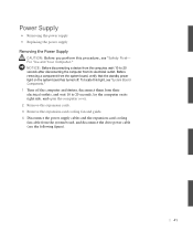
NOTICE: Before disconnecting a device from the computer, wait 10 to 20 seconds, lay the computer on the system board has turned off. For You and Your Computer." To locate this procedure, see "Safety First- ... Supply CAUTION: Before you perform this light, see "System Board Components." 1 Turn off the computer and devices, disconnect them from their electrical outlets, and wait 10 to 20 seconds after disconnecting the computer from its right side, and open the computer cover. 2 Remove the expansion cards. 3 Remove the expansion-card cooling...
NOTICE: Before disconnecting a device from the computer, wait 10 to 20 seconds, lay the computer on the system board has turned off. For You and Your Computer." To locate this procedure, see "Safety First- ... Supply CAUTION: Before you perform this light, see "System Board Components." 1 Turn off the computer and devices, disconnect them from their electrical outlets, and wait 10 to 20 seconds after disconnecting the computer from its right side, and open the computer cover. 2 Remove the expansion cards. 3 Remove the expansion-card cooling...

Service Manual
Page 48
...other sockets. • The system board supports PC600 and PC800 memory modules. Removing a Memory Module NOTICE: Before disconnecting a device from the computer, wait 10 to 20 seconds after disconnecting the computer from the system board, verify that the standby power light on the memory riser boards need to identify...can remain empty. • Mixed pairs of ECC and non-ECC modules all memory sockets on the system board has turned off. www.dell.com | support.dell.com • Mixed pairs of ECC and non-ECC modules all function as non-ECC. • The optional memory riser boards only ...
...other sockets. • The system board supports PC600 and PC800 memory modules. Removing a Memory Module NOTICE: Before disconnecting a device from the computer, wait 10 to 20 seconds after disconnecting the computer from the system board, verify that the standby power light on the memory riser boards need to identify...can remain empty. • Mixed pairs of ECC and non-ECC modules all memory sockets on the system board has turned off. www.dell.com | support.dell.com • Mixed pairs of ECC and non-ECC modules all function as non-ECC. • The optional memory riser boards only ...
Service Manual
Page 50
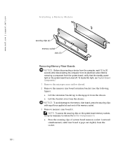
... chassis. a Lift the retention bracket up to disengage it may be necessary to remove the fan for microprocessor 0. www.dell.com | support.dell.com Installing a Memory Module securing clips (2) memory socket slots (2) Removing Memory Riser Boards NOTICE: Before disconnecting a device from the... computer, wait 10 to 20 seconds after disconnecting the computer from the socket. 50 a Press the securing clips of the memory ...
... chassis. a Lift the retention bracket up to disengage it may be necessary to remove the fan for microprocessor 0. www.dell.com | support.dell.com Installing a Memory Module securing clips (2) memory socket slots (2) Removing Memory Riser Boards NOTICE: Before disconnecting a device from the... computer, wait 10 to 20 seconds after disconnecting the computer from the socket. 50 a Press the securing clips of the memory ...

Service Manual
Page 57
..., verify that the standby power light on the system board has turned off the computer and devices, disconnect them from their electrical outlets, and wait 10 to 20 seconds, lay the computer on its electrical outlet. To locate this light, see "System Board Components." 1 Turn off . If you...Slide the drive bracket upward, and remove it from the chassis. For You and Your Computer." NOTICE: Before disconnecting a device from the computer, wait 10 to 20 seconds after disconnecting the computer from its right side, and open the computer cover. 2 If you are replacing. 4 Remove the drive from...
..., verify that the standby power light on the system board has turned off the computer and devices, disconnect them from their electrical outlets, and wait 10 to 20 seconds, lay the computer on its electrical outlet. To locate this light, see "System Board Components." 1 Turn off . If you...Slide the drive bracket upward, and remove it from the chassis. For You and Your Computer." NOTICE: Before disconnecting a device from the computer, wait 10 to 20 seconds after disconnecting the computer from its right side, and open the computer cover. 2 If you are replacing. 4 Remove the drive from...

Service Manual
Page 63
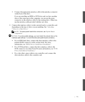
... damage, ensure that has audio output capability, such as a CD drive, connect the audio cable to the audio connector on the back of the drive. 10 Connect the interface cable(s) to the SCSI connector on system board. • Connect the appropriate interface cable to the primary EIDE connector on the system...
... damage, ensure that has audio output capability, such as a CD drive, connect the audio cable to the audio connector on the back of the drive. 10 Connect the interface cable(s) to the SCSI connector on system board. • Connect the appropriate interface cable to the primary EIDE connector on the system...

Service Manual
Page 67
To locate this light, see "System Board Components." 1 Turn off . NOTICE: Before disconnecting a device from the computer, wait 10 to back up your files before you begin this procedure, see the following figure). 67 a Squeeze together the tabs at each side of the drive ..., verify that the standby power light on the system board has turned off the computer and devices, disconnect them from their electrical outlets, and wait 10 to 20 seconds, lay the computer on its electrical outlet. CAUTION: Before you are replacing. 4 Remove the drive from the back of the drive to...
To locate this light, see "System Board Components." 1 Turn off . NOTICE: Before disconnecting a device from the computer, wait 10 to back up your files before you begin this procedure, see the following figure). 67 a Squeeze together the tabs at each side of the drive ..., verify that the standby power light on the system board has turned off the computer and devices, disconnect them from their electrical outlets, and wait 10 to 20 seconds, lay the computer on its electrical outlet. CAUTION: Before you are replacing. 4 Remove the drive from the back of the drive to...
Service Manual
Page 71
... connector on system board. NOTE: To locate system board drive connectors, see "SCSI Device Installation Guidelines." • For a drive that comes with the new drive. 10 Connect the interface cable(s) to the system board or a controller card, depending on the type of the same type in the computer, you must match...
... connector on system board. NOTE: To locate system board drive connectors, see "SCSI Device Installation Guidelines." • For a drive that comes with the new drive. 10 Connect the interface cable(s) to the system board or a controller card, depending on the type of the same type in the computer, you must match...

Service Manual
Page 79
... cover. 2 Press the expansion-card airflow shroud release button. 3 Lift the expansion-card airflow shroud up and away from their electrical outlets, wait at least 10 to remove the expansion-card airflow shroud. For You and Your Computer." 1 Turn off the computer and devices, disconnect them from the computer cover (see...
... cover. 2 Press the expansion-card airflow shroud release button. 3 Lift the expansion-card airflow shroud up and away from their electrical outlets, wait at least 10 to remove the expansion-card airflow shroud. For You and Your Computer." 1 Turn off the computer and devices, disconnect them from the computer cover (see...

Service Manual
Page 83
... MHz. To locate this procedure, see the following figure). 83 NOTICE: Before disconnecting a device from the computer, wait 10 to 20 seconds after disconnecting the computer from their electrical outlets, and wait 10 to 20 seconds, lay the computer on the expansion card retention arm and raise the retention arm (see "Safety...
... MHz. To locate this procedure, see the following figure). 83 NOTICE: Before disconnecting a device from the computer, wait 10 to 20 seconds after disconnecting the computer from their electrical outlets, and wait 10 to 20 seconds, lay the computer on the expansion card retention arm and raise the retention arm (see "Safety...
Service Manual
Page 86
...Cables routed toward the rear of the expansion cards can prevent the computer cover from the expansioncard cooling fan. 9 Close the computer cover. 10 Stand the computer upright. 11 Reconnect the computer and devices to the add-in connectors on the computer back panel (see "Back-Panel ...cables over the expansion cards can prevent proper airflow from closing properly or cause damage to the equipment. Cover was previously removed. www.dell.com | support.dell.com 7 Lower the expansion card retention arm and press it into place, securing the expansion card(s) in the chassis. 8 Connect ...
...Cables routed toward the rear of the expansion cards can prevent the computer cover from the expansioncard cooling fan. 9 Close the computer cover. 10 Stand the computer upright. 11 Reconnect the computer and devices to the add-in connectors on the computer back panel (see "Back-Panel ...cables over the expansion cards can prevent proper airflow from closing properly or cause damage to the equipment. Cover was previously removed. www.dell.com | support.dell.com 7 Lower the expansion card retention arm and press it into place, securing the expansion card(s) in the chassis. 8 Connect ...

Service Manual
Page 87
Removing an Expansion Card CAUTION: Before you need a filler bracket, contact Dell and order part number 81808. Before removing a component from the system board, verify that the standby power light on the system board has turned off ... raise the retention arm (see "Raising the Expansion Card Retention Arm"). 3 If necessary, disconnect any cables connected to maintain FCC certification of your User's Guide. 10 If you are removing the card permanently, install a filler bracket in the empty card-slot opening. NOTE: Installing filler brackets over empty card-slot openings...
Removing an Expansion Card CAUTION: Before you need a filler bracket, contact Dell and order part number 81808. Before removing a component from the system board, verify that the standby power light on the system board has turned off ... raise the retention arm (see "Raising the Expansion Card Retention Arm"). 3 If necessary, disconnect any cables connected to maintain FCC certification of your User's Guide. 10 If you are removing the card permanently, install a filler bracket in the empty card-slot opening. NOTE: Installing filler brackets over empty card-slot openings...

Service Manual
Page 89
... that the standby power light on the system board has turned off the computer and devices, disconnect them from their electrical outlets, wait at least 10 to 20 seconds, lay the computer on its connector on the expansion-card guide. To locate this procedure, see the following figure). 89 For You...
... that the standby power light on the system board has turned off the computer and devices, disconnect them from their electrical outlets, wait at least 10 to 20 seconds, lay the computer on its connector on the expansion-card guide. To locate this procedure, see the following figure). 89 For You...

Service Manual
Page 94
... standby power light on the system board has turned off the computer and devices, disconnect them from their electrical outlets, wait at least 10 to 20 seconds, lay the computer on its right side, and open the computer cover. 2 Remove the front panel. 3 Disconnect ...the control-panel cable from the I/O panel connector. 4 Disconnect the I/O panel cable from the chassis. 94 www.dell.com | support.dell.com Removing the Control Panel CAUTION: Before you perform this light, see "System Board Components." 1 Turn off . To locate this procedure, see "Safety...
... standby power light on the system board has turned off the computer and devices, disconnect them from their electrical outlets, wait at least 10 to 20 seconds, lay the computer on its right side, and open the computer cover. 2 Remove the front panel. 3 Disconnect ...the control-panel cable from the I/O panel connector. 4 Disconnect the I/O panel cable from the chassis. 94 www.dell.com | support.dell.com Removing the Control Panel CAUTION: Before you perform this light, see "System Board Components." 1 Turn off . To locate this procedure, see "Safety...

