Service Manual
Page 4
Removing the Dell Shield 39 Replacing the Dell Shield 40 Power Supply 41 Removing the Power Supply 41 Replacing the Power Supply 43 Computer Memory 45 System Memory Installation Guidelines 47 Removing a Memory Module 48 Installing a Memory Module 49 Removing Memory Riser Boards 50 Installing Memory Riser Boards 53 Disk Drives and Media 55 Installing a CD, Zip, or Other Externally Accessible Drive . . . 57...
Removing the Dell Shield 39 Replacing the Dell Shield 40 Power Supply 41 Removing the Power Supply 41 Replacing the Power Supply 43 Computer Memory 45 System Memory Installation Guidelines 47 Removing a Memory Module 48 Installing a Memory Module 49 Removing Memory Riser Boards 50 Installing Memory Riser Boards 53 Disk Drives and Media 55 Installing a CD, Zip, or Other Externally Accessible Drive . . . 57...
Service Manual
Page 21
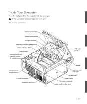
Inside Your Computer The following figure shows the computer with the cover open. NOTE: User service access points are color-coded green. Inside the Computer interior service label diskette drive bracket hard-drive bracket externally accessible-drive bracket chassis intrusion switch control panel memory riser board retention bracket (if needed) microprocessor airflow shroud I/O panel connectors expansion-card slots AGP card brace speaker expansion-card cooling fan system board power supply AC power receptacle power supply airflow vents 21
Inside Your Computer The following figure shows the computer with the cover open. NOTE: User service access points are color-coded green. Inside the Computer interior service label diskette drive bracket hard-drive bracket externally accessible-drive bracket chassis intrusion switch control panel memory riser board retention bracket (if needed) microprocessor airflow shroud I/O panel connectors expansion-card slots AGP card brace speaker expansion-card cooling fan system board power supply AC power receptacle power supply airflow vents 21
Service Manual
Page 45
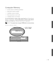
To locate the memory sockets on the system board, see "Memory Riser Board Components." Memory Module Label number of memory devices in RIMM 128MB/16 ECC xxx 45 Computer Memory • System memory installation guidelines • Removing a memory module • Installing a memory module • Removing memory riser boards • Installing memory riser boards To locate the memory sockets on the optional memory riser boards, see "System Board Memory Components." NOTE: The computer does not support RIMMs with six memory devices.
To locate the memory sockets on the system board, see "Memory Riser Board Components." Memory Module Label number of memory devices in RIMM 128MB/16 ECC xxx 45 Computer Memory • System memory installation guidelines • Removing a memory module • Installing a memory module • Removing memory riser boards • Installing memory riser boards To locate the memory sockets on the optional memory riser boards, see "System Board Memory Components." NOTE: The computer does not support RIMMs with six memory devices.
Service Manual
Page 47
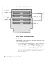
... of components, and speed. See "System Board Memory Components" to -RAM light riser board B socket 4 socket 3 pair 4 socket 2 pair 3 socket 1 pair 2 pair 1 socket 4 socket 3 socket 2 socket 1 System Memory Installation Guidelines • System board installation • Riser board installation System Board Installation When installing memory modules in the system board sockets and not using the optional memory riser boards, observe the following guidelines: • Each...
... of components, and speed. See "System Board Memory Components" to -RAM light riser board B socket 4 socket 3 pair 4 socket 2 pair 3 socket 1 pair 2 pair 1 socket 4 socket 3 socket 2 socket 1 System Memory Installation Guidelines • System board installation • Riser board installation System Board Installation When installing memory modules in the system board sockets and not using the optional memory riser boards, observe the following guidelines: • Each...

Service Manual
Page 48
... remaining pair(s) can remain empty. • Mixed pairs of ECC and non-ECC modules all function as non-ECC. • The optional memory riser boards only support PC800 memory modules. www.dell.com | support.dell.com • Mixed pairs of ECC and non-ECC modules all function as non-ECC. • Be sure to install a RIMM...
... remaining pair(s) can remain empty. • Mixed pairs of ECC and non-ECC modules all function as non-ECC. • The optional memory riser boards only support PC800 memory modules. www.dell.com | support.dell.com • Mixed pairs of ECC and non-ECC modules all function as non-ECC. • Be sure to install a RIMM...
Service Manual
Page 50
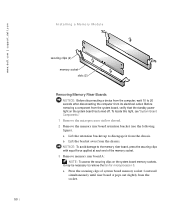
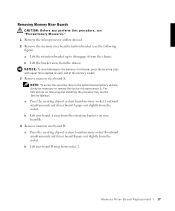
... out slightly from its electrical outlet. a Press the securing clips of the memory socket. 3 Remove memory riser board A: NOTE: To access the securing clips on the system board has turned off. www.dell.com | support.dell.com Installing a Memory Module securing clips (2) memory socket slots (2) Removing Memory Riser Boards NOTICE: Before disconnecting a device from the computer, wait 10 to 20 seconds after...
... out slightly from its electrical outlet. a Press the securing clips of the memory socket. 3 Remove memory riser board A: NOTE: To access the securing clips on the system board has turned off. www.dell.com | support.dell.com Installing a Memory Module securing clips (2) memory socket slots (2) Removing Memory Riser Boards NOTICE: Before disconnecting a device from the computer, wait 10 to 20 seconds after...
Service Manual
Page 51
b Lift riser board A away from the retention brackets on riser board B. 4 Remove memory riser board B: a Press the securing clips of system board memory socket B outward simultaneously until riser board B pops out slightly from socket 2. 51 b Lift riser board B away from the socket.
b Lift riser board A away from the retention brackets on riser board B. 4 Remove memory riser board B: a Press the securing clips of system board memory socket B outward simultaneously until riser board B pops out slightly from socket 2. 51 b Lift riser board B away from the socket.
Service Manual
Page 53
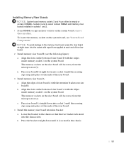
... into place at the ends of the riser board. 4 Install the memory riser board retention bracket: a Lower the bracket to the memory riser board, press the riser board straight down into the socket with equal force applied at the ends of the riser board. 3 Install memory riser board A: a Align the edges of riser board A with the retention brackets on riser board B. b Press riser board B straight down until the securing clips snap...
... into place at the ends of the riser board. 4 Install the memory riser board retention bracket: a Lower the bracket to the memory riser board, press the riser board straight down into the socket with equal force applied at the ends of the riser board. 3 Install memory riser board A: a Align the edges of riser board A with the retention brackets on riser board B. b Press riser board B straight down until the securing clips snap...

Memory Riser Board Replacement
Page 5
... any static charge from your operating system. NOTE: Dell recommends that might harm internal components. Memory Riser Board Replacement 5 Memory Riser Board Replacement This document provides instructions on replacing the memory riser board on the back of the computer or on the computer chassis, such as the padlock loop on the Dell Precision™ WorkStation 530 computer. If a wrist grounding strap is on...
... any static charge from your operating system. NOTE: Dell recommends that might harm internal components. Memory Riser Board Replacement 5 Memory Riser Board Replacement This document provides instructions on replacing the memory riser board on the back of the computer or on the computer chassis, such as the padlock loop on the Dell Precision™ WorkStation 530 computer. If a wrist grounding strap is on...
Memory Riser Board Replacement
Page 6
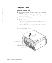
Opening the Computer Cover cover release latch security cable slot padlock ring 6 Memory Riser Board Replacement w w w.d el l.co m | su p po rt. b Raise the back of the cover, and pivot it toward the top of the computer. " 1 If you perform this ...
Opening the Computer Cover cover release latch security cable slot padlock ring 6 Memory Riser Board Replacement w w w.d el l.co m | su p po rt. b Raise the back of the cover, and pivot it toward the top of the computer. " 1 If you perform this ...
Memory Riser Board Replacement
Page 7
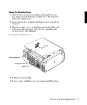
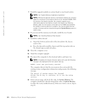
... come loose during your computer, install the padlock. Closing the Computer Cover 1 Check all cable connections, especially those that the release latch clicks into position. Memory Riser Board Replacement 7 Fold cables out of the chassis and into place (see the following figure).
... come loose during your computer, install the padlock. Closing the Computer Cover 1 Check all cable connections, especially those that the release latch clicks into position. Memory Riser Board Replacement 7 Fold cables out of the chassis and into place (see the following figure).
Memory Riser Board Replacement
Page 8
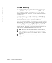
... does not support RIMMs with six memory devices. To locate the memory sockets on the optional memory riser boards, see "System Board Memory Components." To reach the maximum 4-gigabyte (GB) memory total, you must install the optional memory riser boards and use eight 512-MB modules that identifies the number of memory devices installed through the System Memory option in 64-, 128-, 256...
... does not support RIMMs with six memory devices. To locate the memory sockets on the optional memory riser boards, see "System Board Memory Components." To reach the maximum 4-gigabyte (GB) memory total, you must install the optional memory riser boards and use eight 512-MB modules that identifies the number of memory devices installed through the System Memory option in 64-, 128-, 256...
Memory Riser Board Replacement
Page 9
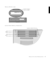
Memory Module L abel 128MB/16 ECC xxx number of memory devices in RIMM System Board Memory Components pair 2 pair 1 socket 4 socket 3 socket 2 socket 1 suspend-to-RAM (STR) light Memory Riser Board Replacement 9
Memory Module L abel 128MB/16 ECC xxx number of memory devices in RIMM System Board Memory Components pair 2 pair 1 socket 4 socket 3 socket 2 socket 1 suspend-to-RAM (STR) light Memory Riser Board Replacement 9
Memory Riser Board Replacement
Page 10
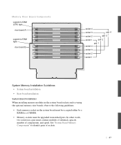
... l a c em e n t Memory riser board A must be installed in system board memory socket 1, and riser board B must be installed in sockets 1 and 2. See "System Board Memory Components" to -RAM light riser board B Memory Riser Board Components socket 4 socket 3 pair 4 socket 2 pair 3 socket 1 pair 2 pair 1 socket 4 socket 3 socket 2 socket 1 System Memory Installation Guidelines Riser Board Installation When installing memory modules using the optional memory riser boards, observe the following guidelines: • The memory riser boards must...
... l a c em e n t Memory riser board A must be installed in system board memory socket 1, and riser board B must be installed in sockets 1 and 2. See "System Board Memory Components" to -RAM light riser board B Memory Riser Board Components socket 4 socket 3 pair 4 socket 2 pair 3 socket 1 pair 2 pair 1 socket 4 socket 3 socket 2 socket 1 System Memory Installation Guidelines Riser Board Installation When installing memory modules using the optional memory riser boards, observe the following guidelines: • The memory riser boards must...
Memory Riser Board Replacement
Page 11
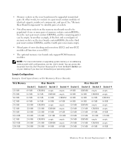
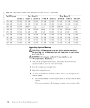
... the first and second pairs of error checking and correction (ECC) and non-ECC modules all memory sockets on addressing memory with Memory Riser Boards Total Memory Riser Board A Riser Board B Socket 1 Socket 2 Socket 3 Socket 4 Socket 1 Socket 2 Socket 3 Socket 4 ...Dell Precision ResourceCD or from the User's Guides icon on the riser boards contain RIMMs, then the third pair must contain CRIMMs, and the fourth pair can be upgraded in a pair must contain modules of identical capacity, number of sockets. • Not all function as non-ECC. • The optional memory riser boards...
... the first and second pairs of error checking and correction (ECC) and non-ECC modules all memory sockets on addressing memory with Memory Riser Boards Total Memory Riser Board A Riser Board B Socket 1 Socket 2 Socket 3 Socket 4 Socket 1 Socket 2 Socket 3 Socket 4 ...Dell Precision ResourceCD or from the User's Guides icon on the riser boards contain RIMMs, then the third pair must contain CRIMMs, and the fourth pair can be upgraded in a pair must contain modules of identical capacity, number of sockets. • Not all function as non-ECC. • The optional memory riser boards...
Memory Riser Board Replacement
Page 12
... em o r y Ri s e r B o a rd Rep l a c em e n t com S a m p l e C o n f i g u r a t i o n s w i t h M e m o r y R i s e r B o a r d s (continued) Total Memory Riser Board A Riser Board B Socket 1 Socket 2 Socket 3 Socket 4 Socket 1 Socket 2 Socket 3 Socket 4 1536 MB 256 MB 256 MB 128 MB 128 MB 256 MB 256 MB 128 MB 128 ...outlets, and wait 10 to 20 seconds. 2 Lay the computer on its right side. 3 Open the computer cover. 4 To access system board memory sockets, remove the microprocessor airflow shroud: a Press down and back on the indentations at the top corners of the shroud. w w w.d ...
... em o r y Ri s e r B o a rd Rep l a c em e n t com S a m p l e C o n f i g u r a t i o n s w i t h M e m o r y R i s e r B o a r d s (continued) Total Memory Riser Board A Riser Board B Socket 1 Socket 2 Socket 3 Socket 4 Socket 1 Socket 2 Socket 3 Socket 4 1536 MB 256 MB 256 MB 128 MB 128 MB 256 MB 256 MB 128 MB 128 ...outlets, and wait 10 to 20 seconds. 2 Lay the computer on its right side. 3 Open the computer cover. 4 To access system board memory sockets, remove the microprocessor airflow shroud: a Press down and back on the indentations at the top corners of the shroud. w w w.d ...
Memory Riser Board Replacement
Page 13
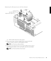
NOTE: See "Removing a Memory Module." 6 If you have the optional memory riser boards installed and you plan to install upgrade modules on the riser boards, remove the riser boards. NOTE: See "Removing Memory Riser Boards." M e mo r y R i s er B o a rd Re p la c e m en t 13 Removing the Microprocessor Airflow Shroud airflow shroud top anchor tabs (2) bottom anchor tabs (2) b Lift the airflow shroud out of the chassis. 5 If necessary, remove memory modules that occupy system board sockets in which you plan to install upgrade modules.
NOTE: See "Removing a Memory Module." 6 If you have the optional memory riser boards installed and you plan to install upgrade modules on the riser boards, remove the riser boards. NOTE: See "Removing Memory Riser Boards." M e mo r y R i s er B o a rd Re p la c e m en t 13 Removing the Microprocessor Airflow Shroud airflow shroud top anchor tabs (2) bottom anchor tabs (2) b Lift the airflow shroud out of the chassis. 5 If necessary, remove memory modules that occupy system board sockets in which you plan to install upgrade modules.
Memory Riser Board Replacement
Page 14
...the memory riser boards installed, the computer supports up : ALERT! NOTE: See "Installing Memory Riser Boards." 9 Install the airflow shroud: a Insert the bottom anchor tabs of 64 memory devices on . Cover was previously removed. NOTE: See "System Memory Installation Guidelines." NOTE: Without the optional memory riser boards ... shroud toward the chassis until the top anchor tabs on each riser board). com 7 Install the upgrade modules in system setup. 8 If you removed the memory riser boards, install the riser boards. d ell. The computer should have already changed . See...
...the memory riser boards installed, the computer supports up : ALERT! NOTE: See "Installing Memory Riser Boards." 9 Install the airflow shroud: a Insert the bottom anchor tabs of 64 memory devices on . Cover was previously removed. NOTE: See "System Memory Installation Guidelines." NOTE: Without the optional memory riser boards ... shroud toward the chassis until the top anchor tabs on each riser board). com 7 Install the upgrade modules in system setup. 8 If you removed the memory riser boards, install the riser boards. d ell. The computer should have already changed . See...
Memory Riser Board Replacement
Page 17
... force applied at each end of the memory socket. 3 Remove memory riser board A: NOTE: To access the securing clips on riser board B. 4 Remove memory riser board B: a Press the securing clips of system board memory socket 1 outward simultaneously until riser board B pops out slightly from the socket. a Press the securing clips of system board memory socket B outward simultaneously until riser board A pops out slightly from the socket. NOTICE...
... force applied at each end of the memory socket. 3 Remove memory riser board A: NOTE: To access the securing clips on riser board B. 4 Remove memory riser board B: a Press the securing clips of system board memory socket 1 outward simultaneously until riser board B pops out slightly from the socket. a Press the securing clips of system board memory socket B outward simultaneously until riser board A pops out slightly from the socket. NOTICE...
Memory Riser Board Replacement
Page 19
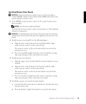
... figure): a Align the slots on the bottom of riser board A with the ridges inside memory socket 2 on the system board. To locate the memory sockets on the system board, remove those modules. b Press riser board B straight down into place at each end of the riser board. 2 Install memory riser board B (see "System Board Memory Components." Installing Memory Riser Boards NOTICE: System board memory sockets 3 and 4 can either be empty or...
... figure): a Align the slots on the bottom of riser board A with the ridges inside memory socket 2 on the system board. To locate the memory sockets on the system board, remove those modules. b Press riser board B straight down into place at each end of the riser board. 2 Install memory riser board B (see "System Board Memory Components." Installing Memory Riser Boards NOTICE: System board memory sockets 3 and 4 can either be empty or...


