
Service Manual
Page 9
...contacts on a card and avoid touching pins on the system board has turned off the computer and any static electricity that the standby power light on a chip. 3 Disconnect your computer and peripherals from its electrical outlet. CAUTION: There is a danger of the chassis. Before ...board, verify that might harm internal components. Also, disconnect any static charge from your body before touching anything inside your online Dell documentation or otherwise provided to 20 seconds after disconnecting the computer from their power sources. NOTICE: Do not attempt to service ...
...contacts on a card and avoid touching pins on the system board has turned off the computer and any static electricity that the standby power light on a chip. 3 Disconnect your computer and peripherals from its electrical outlet. CAUTION: There is a danger of the chassis. Before ...board, verify that might harm internal components. Also, disconnect any static charge from your body before touching anything inside your online Dell documentation or otherwise provided to 20 seconds after disconnecting the computer from their power sources. NOTICE: Do not attempt to service ...

Service Manual
Page 15
... disconnect them from their electrical outlets, and wait 10 to 20 seconds after disconnecting the computer from the system board, verify that the standby power light on its electrical outlet. For You and Your Computer." NOTICE: Before disconnecting a device from the computer, wait 10 to 20 seconds. 2 If... you perform this light, see "System Board Components." 1 Turn off . b Raise the back of the cover, and pivot it toward the top of the computer. 15 ...
... disconnect them from their electrical outlets, and wait 10 to 20 seconds after disconnecting the computer from the system board, verify that the standby power light on its electrical outlet. For You and Your Computer." NOTICE: Before disconnecting a device from the computer, wait 10 to 20 seconds. 2 If... you perform this light, see "System Board Components." 1 Turn off . b Raise the back of the cover, and pivot it toward the top of the computer. 15 ...
Service Manual
Page 24
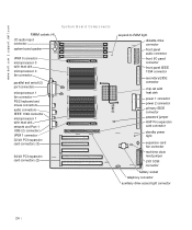
www.dell.com | support.dell.com RIMM sockets (4) CD audio input connector system board speaker System Board Components VRM 0 connector microprocessor 0 with heat sink microprocessor 0 fan connector parallel and serial (2) ... 1 with heat sink network and Port 1 USB (2) connectors VRM 1 connector 32-bit PCI expansion card connectors (3) 64-bit PCI expansion card connectors (2) suspend-to-RAM light diskette-drive connector front panel audio connector front I/O panel connector front panel IEEE 1394 connector secondary EIDE connector chip set with heat sink power 1 connector...
www.dell.com | support.dell.com RIMM sockets (4) CD audio input connector system board speaker System Board Components VRM 0 connector microprocessor 0 with heat sink microprocessor 0 fan connector parallel and serial (2) ... 1 with heat sink network and Port 1 USB (2) connectors VRM 1 connector 32-bit PCI expansion card connectors (3) 64-bit PCI expansion card connectors (2) suspend-to-RAM light diskette-drive connector front panel audio connector front I/O panel connector front panel IEEE 1394 connector secondary EIDE connector chip set with heat sink power 1 connector...

Service Manual
Page 25
... FRONT1394 IDE1 IDE2 KYBD_MOUSE PANEL PARALLEL_SERIAL PCIn POWER1 POWER2 PSWD RIMM_n RTCRST Label IEEE 1394 connector AGP Pro card connector Audio connectors Auxiliary drive access light connector Battery socket CD audio input connector Microprocessor 0 with heat sink Microprocessor 1 with heat sink Diskette-drive connector Expansion card fan connector Microprocessor 0 fan connector...
... FRONT1394 IDE1 IDE2 KYBD_MOUSE PANEL PARALLEL_SERIAL PCIn POWER1 POWER2 PSWD RIMM_n RTCRST Label IEEE 1394 connector AGP Pro card connector Audio connectors Auxiliary drive access light connector Battery socket CD audio input connector Microprocessor 0 with heat sink Microprocessor 1 with heat sink Diskette-drive connector Expansion card fan connector Microprocessor 0 fan connector...

Service Manual
Page 26
... its pin(s) and carefully fit it down onto the pin(s) indicated. 26 www.dell.com | support.dell.com S y s t e m B o a r d L a b e l s (continued) Connector or Component SCSI SPKR STANDBY_LED STR_LED TAPI/MODEM USB_NIC VRM_0 VRM_1 Label LVD SCSI connector System board speaker Standby power light Suspend-to your computer or unpredictable results may occur. To change a jumper...
... its pin(s) and carefully fit it down onto the pin(s) indicated. 26 www.dell.com | support.dell.com S y s t e m B o a r d L a b e l s (continued) Connector or Component SCSI SPKR STANDBY_LED STR_LED TAPI/MODEM USB_NIC VRM_0 VRM_1 Label LVD SCSI connector System board speaker Standby power light Suspend-to your computer or unpredictable results may occur. To change a jumper...
Service Manual
Page 41
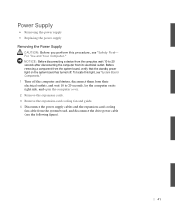
Before removing a component from the system board, verify that the standby power light on its right side, and open the computer cover. 2 Remove the expansion cards. 3 Remove the expansion-card cooling fan and guide. 4 Disconnect the power supply ... cable (see "Safety First- Power Supply • Removing the power supply • Replacing the power supply Removing the Power Supply CAUTION: Before you perform this light, see "System Board Components." 1 Turn off . To locate this procedure, see the following figure). 41 For You and Your Computer."
Before removing a component from the system board, verify that the standby power light on its right side, and open the computer cover. 2 Remove the expansion cards. 3 Remove the expansion-card cooling fan and guide. 4 Disconnect the power supply ... cable (see "Safety First- Power Supply • Removing the power supply • Replacing the power supply Removing the Power Supply CAUTION: Before you perform this light, see "System Board Components." 1 Turn off . To locate this procedure, see the following figure). 41 For You and Your Computer."
Service Manual
Page 47
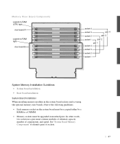
See "System Board Memory Components" to -RAM light riser board B socket 4 socket 3 pair 4 socket 2 pair 3 socket 1 pair 2 pair 1 socket 4 socket 3 socket 2 socket 1 System Memory Installation Guidelines • System board installation • Riser board ... by a RIMM or a CRIMM. • Memory sockets must contain modules of identical capacity, number of sockets. 47 Memory Riser Board Components suspend-to-RAM (STR) light riser board A suspend-to identify pairs of components, and speed.
See "System Board Memory Components" to -RAM light riser board B socket 4 socket 3 pair 4 socket 2 pair 3 socket 1 pair 2 pair 1 socket 4 socket 3 socket 2 socket 1 System Memory Installation Guidelines • System board installation • Riser board ... by a RIMM or a CRIMM. • Memory sockets must contain modules of identical capacity, number of sockets. 47 Memory Riser Board Components suspend-to-RAM (STR) light riser board A suspend-to identify pairs of components, and speed.

Service Manual
Page 48
...Memory Module NOTICE: Before disconnecting a device from its electrical outlet. Before removing a component from the system board, verify that the standby power light on the memory riser boards need to 20 seconds after disconnecting the computer from the computer, wait 10 to be populated: if one or ... sockets contain RIMMs, then the next pair must contain CRIMMs, and the remaining pair(s) can be empty. To locate this light, see "System Board Components." 48 www.dell.com | support.dell.com • Mixed pairs of ECC and non-ECC modules all function as non-ECC. • Be sure to install...
...Memory Module NOTICE: Before disconnecting a device from its electrical outlet. Before removing a component from the system board, verify that the standby power light on the memory riser boards need to 20 seconds after disconnecting the computer from the computer, wait 10 to be populated: if one or ... sockets contain RIMMs, then the next pair must contain CRIMMs, and the remaining pair(s) can be empty. To locate this light, see "System Board Components." 48 www.dell.com | support.dell.com • Mixed pairs of ECC and non-ECC modules all function as non-ECC. • Be sure to install...
Service Manual
Page 50
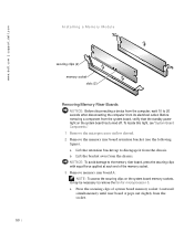
.... NOTICE: To avoid damage to 20 seconds after disconnecting the computer from its electrical outlet. To locate this light, see "System Board Components." 1 Remove the microprocessor airflow shroud. 2 Remove the memory riser board retention bracket (see the following ...figure). www.dell.com | support.dell.com Installing a Memory Module securing clips (2) memory socket slots (2) Removing Memory Riser Boards NOTICE: Before disconnecting a device from ...
.... NOTICE: To avoid damage to 20 seconds after disconnecting the computer from its electrical outlet. To locate this light, see "System Board Components." 1 Remove the microprocessor airflow shroud. 2 Remove the memory riser board retention bracket (see the following ...figure). www.dell.com | support.dell.com Installing a Memory Module securing clips (2) memory socket slots (2) Removing Memory Riser Boards NOTICE: Before disconnecting a device from ...

Service Manual
Page 57
Before removing a component from the system board, verify that the standby power light on its electrical outlet. b Slide the drive bracket upward, and remove it from its right side, and open the computer cover. 2 If you are replacing a ... devices, disconnect them from their electrical outlets, and wait 10 to back up your files before you begin this procedure. CAUTION: Before you perform this light, see "System Board Components." 1 Turn off . For You and Your Computer." NOTICE: Before disconnecting a device from the computer, wait 10 to 20 seconds after disconnecting...
Before removing a component from the system board, verify that the standby power light on its electrical outlet. b Slide the drive bracket upward, and remove it from its right side, and open the computer cover. 2 If you are replacing a ... devices, disconnect them from their electrical outlets, and wait 10 to back up your files before you begin this procedure. CAUTION: Before you perform this light, see "System Board Components." 1 Turn off . For You and Your Computer." NOTICE: Before disconnecting a device from the computer, wait 10 to 20 seconds after disconnecting...

Service Manual
Page 67
..., and remove it from the chassis. For You and Your Computer." To locate this procedure, see the following figure). 67 CAUTION: Before you perform this light, see "System Board Components." 1 Turn off the computer and devices, disconnect them from the system board, verify that contains data you want to keep, be... the system board has turned off. a Squeeze together the tabs at each side of the drive you are replacing a hard drive that the standby power light on its electrical outlet.
..., and remove it from the chassis. For You and Your Computer." To locate this procedure, see the following figure). 67 CAUTION: Before you perform this light, see "System Board Components." 1 Turn off the computer and devices, disconnect them from the system board, verify that contains data you want to keep, be... the system board has turned off. a Squeeze together the tabs at each side of the drive you are replacing a hard drive that the standby power light on its electrical outlet.

Service Manual
Page 83
To locate this procedure, see the following figure). 83 Installing an Expansion Card CAUTION: Before you perform this light, see "System Board Components." 1 Turn off . For You and Your Computer." NOTICE: Before disconnecting a device from the computer, wait 10 to 20 ...disconnect them from their electrical outlets, and wait 10 to 20 seconds after disconnecting the computer from the system board, verify that the standby power light on the expansion card retention arm and raise the retention arm (see "Safety First- Before removing a component from its electrical outlet. You can...
To locate this procedure, see the following figure). 83 Installing an Expansion Card CAUTION: Before you perform this light, see "System Board Components." 1 Turn off . For You and Your Computer." NOTICE: Before disconnecting a device from the computer, wait 10 to 20 ...disconnect them from their electrical outlets, and wait 10 to 20 seconds after disconnecting the computer from the system board, verify that the standby power light on the expansion card retention arm and raise the retention arm (see "Safety First- Before removing a component from its electrical outlet. You can...

Service Manual
Page 85
Insert the card firmly into the expansion-card connector. To guard against electrical shock, be sure to a network. To locate this light, see the following figure). If the expansion card is full-length, insert the end of the card into the expansion-card guide bracket as ...you lower the card toward its electrical outlet before installing any expansion cards and verify that the standby power light on the system board (see "System Board Components." 6 Insert the expansion card into the expansion-card connector on the system board has turned off....
Insert the card firmly into the expansion-card connector. To guard against electrical shock, be sure to a network. To locate this light, see the following figure). If the expansion card is full-length, insert the end of the card into the expansion-card guide bracket as ...you lower the card toward its electrical outlet before installing any expansion cards and verify that the standby power light on the system board (see "System Board Components." 6 Insert the expansion card into the expansion-card connector on the system board has turned off....

Service Manual
Page 87
... NOTE: If enabled, the Chassis Intrusion option will cause the following steps: 87 Removing an Expansion Card CAUTION: Before you perform this light, see "System Board Components." 1 Turn off . NOTE: Installing filler brackets over empty card-slot openings is necessary to 20 seconds ...after disconnecting the computer from its connector. 5 If you need a filler bracket, contact Dell and order part number 81808. Before removing a component from the computer, wait 10 to maintain FCC certification of its electrical outlet. ...
... NOTE: If enabled, the Chassis Intrusion option will cause the following steps: 87 Removing an Expansion Card CAUTION: Before you perform this light, see "System Board Components." 1 Turn off . NOTE: Installing filler brackets over empty card-slot openings is necessary to 20 seconds ...after disconnecting the computer from its connector. 5 If you need a filler bracket, contact Dell and order part number 81808. Before removing a component from the computer, wait 10 to maintain FCC certification of its electrical outlet. ...

Service Manual
Page 89
... Components." 1 Turn off . NOTE: There may not be any full-length expansion cards. To locate this light, see "System Board Components." 4 Press the release tabs outward from the system board, verify that the standby power light on the system board (FAN_CCAG). Expansion-Card Cooling Fan and Guide • Removing an expansion-card...
... Components." 1 Turn off . NOTE: There may not be any full-length expansion cards. To locate this light, see "System Board Components." 4 Press the release tabs outward from the system board, verify that the standby power light on the system board (FAN_CCAG). Expansion-Card Cooling Fan and Guide • Removing an expansion-card...

Service Manual
Page 93
Control Panel Components alignment hole control-panel connector hard-drive access light power button screw hole 93 Control Panel • Components • Removing the control panel • Replacing the control panel Components The following figure shows the control panel and the location of its principal connectors and components.
Control Panel Components alignment hole control-panel connector hard-drive access light power button screw hole 93 Control Panel • Components • Removing the control panel • Replacing the control panel Components The following figure shows the control panel and the location of its principal connectors and components.

Service Manual
Page 94
www.dell.com | support.dell.com Removing the Control Panel CAUTION: Before you perform this light, see "System Board Components." 1 Turn off . To locate this procedure, see "System Board Components." 5 Remove the mounting screw from the control panel. 6 Lift the control ... system board connector, see "Safety First- NOTICE: Before disconnecting a device from the computer or removing a component from the system board, verify that the standby power light on the system board. For You and Your Computer."
www.dell.com | support.dell.com Removing the Control Panel CAUTION: Before you perform this light, see "System Board Components." 1 Turn off . To locate this procedure, see "System Board Components." 5 Remove the mounting screw from the control panel. 6 Lift the control ... system board connector, see "Safety First- NOTICE: Before disconnecting a device from the computer or removing a component from the system board, verify that the standby power light on the system board. For You and Your Computer."

Service Manual
Page 97
... and components. I/O Panel Components front panel audio connector control panel connector speaker/headphone jack chassis intrusion switch connector Port 2 USB connectors (2) IEEE 1394 connector diagnostic lights system board connector front panel IEEE 1394 connector chassis speaker connector Removing the I /O panel and the location of its right side, and remove the computer...
... and components. I/O Panel Components front panel audio connector control panel connector speaker/headphone jack chassis intrusion switch connector Port 2 USB connectors (2) IEEE 1394 connector diagnostic lights system board connector front panel IEEE 1394 connector chassis speaker connector Removing the I /O panel and the location of its right side, and remove the computer...

Service Manual
Page 99
NOTICE: Before disconnecting a device from the computer or removing a component from the system board, verify that the standby power light on its slot on the left side of the chassis. 6 Lift the chassis intrusion switch and switch cable away from the chassis. 99 To locate ...). Chassis Intrusion Switch • Removing the chassis intrusion switch • Replacing the chassis intrusion switch Removing the Chassis Intrusion Switch CAUTION: Before you perform this light, see "Safety First-
NOTICE: Before disconnecting a device from the computer or removing a component from the system board, verify that the standby power light on its slot on the left side of the chassis. 6 Lift the chassis intrusion switch and switch cable away from the chassis. 99 To locate ...). Chassis Intrusion Switch • Removing the chassis intrusion switch • Replacing the chassis intrusion switch Removing the Chassis Intrusion Switch CAUTION: Before you perform this light, see "Safety First-

Service Manual
Page 101
NOTICE: Before disconnecting a device from the computer or removing a component from the system board, verify that the standby power light on its right side, and open the computer cover. 2 Disconnect the speaker cable from the I/O connector. 3 Disconnect the speaker cable from their electrical outlets, wait ... this procedure, see "System Board Components." 1 Turn off . Speaker • Removing the speaker • Replacing the speaker Removing the Speaker CAUTION: Before you perform this light, see "Safety First- For You and Your Computer."
NOTICE: Before disconnecting a device from the computer or removing a component from the system board, verify that the standby power light on its right side, and open the computer cover. 2 Disconnect the speaker cable from the I/O connector. 3 Disconnect the speaker cable from their electrical outlets, wait ... this procedure, see "System Board Components." 1 Turn off . Speaker • Removing the speaker • Replacing the speaker Removing the Speaker CAUTION: Before you perform this light, see "Safety First- For You and Your Computer."


