
Service Manual
Page 7
SECTION 1 Before You Begin Safety First-For You and Your Computer Protecting Against Electrostatic Discharge www.dell.com | support.dell.com
SECTION 1 Before You Begin Safety First-For You and Your Computer Protecting Against Electrostatic Discharge www.dell.com | support.dell.com

Service Manual
Page 10
...the locking tabs before you are correctly oriented and aligned. • Handle components and cards with locking tabs; In addition, Dell recommends that you pull connectors apart, keep them evenly aligned to avoid bending any telephone or telecommunication lines from the computer. Also...Also see "Protecting Against Electrostatic Discharge." Hold a component such as a microprocessor chip by its edges, not by its pins. www.dell.com | support.dell.com Also, disconnect any connector pins. Some cables have a connector with care. Do not touch the components or contacts on the cable...
...the locking tabs before you are correctly oriented and aligned. • Handle components and cards with locking tabs; In addition, Dell recommends that you pull connectors apart, keep them evenly aligned to avoid bending any telephone or telecommunication lines from the computer. Also...Also see "Protecting Against Electrostatic Discharge." Hold a component such as a microprocessor chip by its edges, not by its pins. www.dell.com | support.dell.com Also, disconnect any connector pins. Some cables have a connector with care. Do not touch the components or contacts on the cable...

Service Manual
Page 13
SECTION 2 Removing and Installing Parts Computer Cover Interior Service Label Inside Your Computer System Board Components Drive Door Front Panel Front-Panel Inserts Front-Panel Button Dell Shield Power Supply Computer Memory Disk Drives and Media Expansion-Card Airflow Shroud Expansion Cards Expansion-Card Cooling Fan and Guide Control Panel I/O Panel Chassis Intrusion Switch www.dell.com | support.dell.com
SECTION 2 Removing and Installing Parts Computer Cover Interior Service Label Inside Your Computer System Board Components Drive Door Front Panel Front-Panel Inserts Front-Panel Button Dell Shield Power Supply Computer Memory Disk Drives and Media Expansion-Card Airflow Shroud Expansion Cards Expansion-Card Cooling Fan and Guide Control Panel I/O Panel Chassis Intrusion Switch www.dell.com | support.dell.com

Service Manual
Page 16
Fold cables out of the chassis and into position (see the following figure). www.dell.com | support.dell.com Opening the Computer Cover cover release latch padlock ring Closing the Computer Cover 1 Check all cable connections, especially those that no tools or extra ...
Fold cables out of the chassis and into position (see the following figure). www.dell.com | support.dell.com Opening the Computer Cover cover release latch padlock ring Closing the Computer Cover 1 Check all cable connections, especially those that no tools or extra ...
Service Manual
Page 24
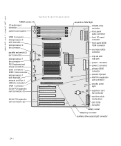
www.dell.com | support.dell.com RIMM sockets (4) CD audio input connector system board speaker System Board Components VRM 0 connector microprocessor 0 with heat sink microprocessor 0 fan connector parallel and serial (2) ...
www.dell.com | support.dell.com RIMM sockets (4) CD audio input connector system board speaker System Board Components VRM 0 connector microprocessor 0 with heat sink microprocessor 0 fan connector parallel and serial (2) ...

Service Manual
Page 26
... fit it down onto the pin(s) indicated. 26 To locate this light, see "System Board Components." To change a jumper setting, pull the plug off . www.dell.com | support.dell.com S y s t e m B o a r d L a b e l s (continued) Connector or Component SCSI SPKR STANDBY_LED STR_LED TAPI/MODEM USB_NIC VRM_0 VRM_1 Label LVD SCSI connector System board speaker Standby power light...
... fit it down onto the pin(s) indicated. 26 To locate this light, see "System Board Components." To change a jumper setting, pull the plug off . www.dell.com | support.dell.com S y s t e m B o a r d L a b e l s (continued) Connector or Component SCSI SPKR STANDBY_LED STR_LED TAPI/MODEM USB_NIC VRM_0 VRM_1 Label LVD SCSI connector System board speaker Standby power light...

Service Manual
Page 30
Replacing the Drive Door To replace the drive door, perform the removal procedures in reverse. 30 www.dell.com | support.dell.com Removing the Drive Door top hinge bottom hinge 3 Lift the bottom hinge off of the chassis.
Replacing the Drive Door To replace the drive door, perform the removal procedures in reverse. 30 www.dell.com | support.dell.com Removing the Drive Door top hinge bottom hinge 3 Lift the bottom hinge off of the chassis.

Service Manual
Page 32
Replacing the Front Panel Fit the seven front-panel retaining hooks into the recessed slots at the bottom of the panel outward, away from the chassis. 5 Pull the panel downward, away from the chassis. Perform the removal procedures in reverse. 32 www.dell.com | support.dell.com Removing the Front Panel front-panel release buttons (7) 4 Close the computer cover halfway and rotate the top of the chassis.
Replacing the Front Panel Fit the seven front-panel retaining hooks into the recessed slots at the bottom of the panel outward, away from the chassis. 5 Pull the panel downward, away from the chassis. Perform the removal procedures in reverse. 32 www.dell.com | support.dell.com Removing the Front Panel front-panel release buttons (7) 4 Close the computer cover halfway and rotate the top of the chassis.

Service Manual
Page 34
www.dell.com | support.dell.com Removing Front-Panel Inserts front panel securing tab front-panel insert securing tab Replacing Front-Panel Inserts 1 Connect and replace any disk drives you removed from the chassis drive bay. 2 Close the computer cover and stand the computer upright. 3 Replace the front-panel insert. b Insert the left securing tab into place. 34 c Press the right securing tab into the drive bay until the panel snaps into the drive bay. a Facing the front panel, open the drive door.
www.dell.com | support.dell.com Removing Front-Panel Inserts front panel securing tab front-panel insert securing tab Replacing Front-Panel Inserts 1 Connect and replace any disk drives you removed from the chassis drive bay. 2 Close the computer cover and stand the computer upright. 3 Replace the front-panel insert. b Insert the left securing tab into place. 34 c Press the right securing tab into the drive bay until the panel snaps into the drive bay. a Facing the front panel, open the drive door.

Service Manual
Page 40
www.dell.com | support.dell.com Replacing the Dell Shield To replace the Dell shield, perform the removal procedure in reverse. 40
www.dell.com | support.dell.com Replacing the Dell Shield To replace the Dell shield, perform the removal procedure in reverse. 40

Service Manual
Page 42
b Slide the cable retainer to the right. c Lift the cable retainer out of the four securing slots in the chassis. 42 a Pull up on the cable retainer release button. www.dell.com | support.dell.com Removing the Plastic Cable Retainer drive power cable cable retainer release button expansion-card cooling fan cable power supply cables 5 Remove the cable retainer.
b Slide the cable retainer to the right. c Lift the cable retainer out of the four securing slots in the chassis. 42 a Pull up on the cable retainer release button. www.dell.com | support.dell.com Removing the Plastic Cable Retainer drive power cable cable retainer release button expansion-card cooling fan cable power supply cables 5 Remove the cable retainer.

Service Manual
Page 44
b Slide the cable retainer to the left until it locks into the four securing slots in the chassis. www.dell.com | support.dell.com a Place the cable retainer into place. 5 Connect the power supply cables and the expansion-card cooling fan cable to the system board, and connect the drive power cable. 6 Replace the expansion-card cooling fan and guide. 7 Install the expansion cards. 8 Close the computer cover and restart the computer. 44
b Slide the cable retainer to the left until it locks into the four securing slots in the chassis. www.dell.com | support.dell.com a Place the cable retainer into place. 5 Connect the power supply cables and the expansion-card cooling fan cable to the system board, and connect the drive power cable. 6 Replace the expansion-card cooling fan and guide. 7 Install the expansion cards. 8 Close the computer cover and restart the computer. 44
Service Manual
Page 45
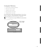
Memory Module Label number of memory devices in RIMM 128MB/16 ECC xxx 45 NOTE: The computer does not support RIMMs with six memory devices. To locate the memory sockets on the system board, see "Memory Riser Board Components." Computer Memory • System memory installation guidelines • Removing a memory module • Installing a memory module • Removing memory riser boards • Installing memory riser boards To locate the memory sockets on the optional memory riser boards, see "System Board Memory Components."
Memory Module Label number of memory devices in RIMM 128MB/16 ECC xxx 45 NOTE: The computer does not support RIMMs with six memory devices. To locate the memory sockets on the system board, see "Memory Riser Board Components." Computer Memory • System memory installation guidelines • Removing a memory module • Installing a memory module • Removing memory riser boards • Installing memory riser boards To locate the memory sockets on the optional memory riser boards, see "System Board Memory Components."

Service Manual
Page 48
www.dell.com | support.dell.com • Mixed pairs of ECC and non-ECC modules all function as non-ECC. • The optional memory riser boards only support PC800 memory modules. System board memory sockets 3 and 4 can remain empty. • Mixed pairs of ECC and non-ECC ...of components, and speed. Before removing a component from the computer, wait 10 to be empty. In other sockets. • The system board supports PC600 and PC800 memory modules. Removing a Memory Module NOTICE: Before disconnecting a device from the system board, verify that the standby power light ...
www.dell.com | support.dell.com • Mixed pairs of ECC and non-ECC modules all function as non-ECC. • The optional memory riser boards only support PC800 memory modules. System board memory sockets 3 and 4 can remain empty. • Mixed pairs of ECC and non-ECC ...of components, and speed. Before removing a component from the computer, wait 10 to be empty. In other sockets. • The system board supports PC600 and PC800 memory modules. Removing a Memory Module NOTICE: Before disconnecting a device from the system board, verify that the standby power light ...
Service Manual
Page 50
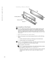
... clips with equal force applied at each end of system board memory socket 1 outward simultaneously until riser board A pops out slightly from the chassis. www.dell.com | support.dell.com Installing a Memory Module securing clips (2) memory socket slots (2) Removing Memory Riser Boards NOTICE: Before disconnecting a device from the computer, wait 10 to 20...
... clips with equal force applied at each end of system board memory socket 1 outward simultaneously until riser board A pops out slightly from the chassis. www.dell.com | support.dell.com Installing a Memory Module securing clips (2) memory socket slots (2) Removing Memory Riser Boards NOTICE: Before disconnecting a device from the computer, wait 10 to 20...

Service Manual
Page 60
Attaching Bracket Rails for an Externally Accessible Drive drive bracket rails (2) screws (4) 7 Slide the drive/bracket assembly into the drive bay until both drive bracket tabs snap securely into place (see the following figure). 60 www.dell.com | support.dell.com NOTE: If you are not replacing an existing drive and the new drive does not have bracket rails attached, install the extra rail set that is located inside your computer in an empty drive bay.
Attaching Bracket Rails for an Externally Accessible Drive drive bracket rails (2) screws (4) 7 Slide the drive/bracket assembly into the drive bay until both drive bracket tabs snap securely into place (see the following figure). 60 www.dell.com | support.dell.com NOTE: If you are not replacing an existing drive and the new drive does not have bracket rails attached, install the extra rail set that is located inside your computer in an empty drive bay.

Service Manual
Page 62
www.dell.com | support.dell.com Installing the Diskette Drive 8 If you are installing a drive that the configuration is correct for correct configuration. 9 Connect the cables to the power input connector on the back of the drive. 62 See the documentation that accompanied the drive and controller card to verify that has its own controller card, install the controller card in an expansion slot. Change any settings necessary for your computer. See "Attaching Cables for an Externally Accessible Drive." • Connect a DC power cable to the drive.
www.dell.com | support.dell.com Installing the Diskette Drive 8 If you are installing a drive that the configuration is correct for correct configuration. 9 Connect the cables to the power input connector on the back of the drive. 62 See the documentation that accompanied the drive and controller card to verify that has its own controller card, install the controller card in an expansion slot. Change any settings necessary for your computer. See "Attaching Cables for an Externally Accessible Drive." • Connect a DC power cable to the drive.
Service Manual
Page 64
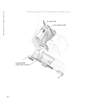
www.dell.com | support.dell.com Attaching Cables for an Externally Accessible Drive DC power cable drive interface cable secondary EIDE system board connector 64
www.dell.com | support.dell.com Attaching Cables for an Externally Accessible Drive DC power cable drive interface cable secondary EIDE system board connector 64
Service Manual
Page 66
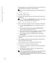
... system's documentation for instructions. 18 Test the drive to verify that came with the drive for information on testing the drive. www.dell.com | support.dell.com From inside the cover, press the ends of the insert outward with your new diskette drive. • If you installed an...enabled, the Chassis Intrusion option will cause the following message to the next step. NOTE: If you installed is a hard drive, run the Dell Diagnostics to their own operating software and documentation. After you install a tape drive, refer to the documentation that it is operating properly. •...
... system's documentation for instructions. 18 Test the drive to verify that came with the drive for information on testing the drive. www.dell.com | support.dell.com From inside the cover, press the ends of the insert outward with your new diskette drive. • If you installed an...enabled, the Chassis Intrusion option will cause the following message to the next step. NOTE: If you installed is a hard drive, run the Dell Diagnostics to their own operating software and documentation. After you install a tape drive, refer to the documentation that it is operating properly. •...

Service Manual
Page 68
... not have bracket rails attached, remove the rails from the old drive by touching an unpainted metal surface on the back of the computer. www.dell.com | support.dell.com Removing a Hard Drive 5 Unpack the replacement drive and prepare it for your computer. Change any settings necessary for installation.
... not have bracket rails attached, remove the rails from the old drive by touching an unpainted metal surface on the back of the computer. www.dell.com | support.dell.com Removing a Hard Drive 5 Unpack the replacement drive and prepare it for your computer. Change any settings necessary for installation.


