
Getting Started Guide
Page 5
...information about other documents you may need when setting up to power the RAID controller system memory (cache) for a minimum of 72 hours in case of a power outage • Redundant hot-plug power supply and cooling modules that are combined for easy serviceability Getting Started ... capability; For more information, refer to the Dell PowerVault MD Systems Support Matrix at support.dell.com. • Support for a wide range of servers. (For additional support information, refer to the Dell PowerVault MD Systems Support Matrix at support.dell.com). • Support for both simplex (...
...information about other documents you may need when setting up to power the RAID controller system memory (cache) for a minimum of 72 hours in case of a power outage • Redundant hot-plug power supply and cooling modules that are combined for easy serviceability Getting Started ... capability; For more information, refer to the Dell PowerVault MD Systems Support Matrix at support.dell.com. • Support for a wide range of servers. (For additional support information, refer to the Dell PowerVault MD Systems Support Matrix at support.dell.com). • Support for both simplex (...

Getting Started Guide
Page 9
Attach the system power cable to the power supply/cooling fan modules. Getting Started With Your System 7 Connect the Power Cables and Power Cord Retention Bracket Connect both power cables to the bracket's cable clasp. Repeat the procedure for the second power supply. Attach the power cord retention bracket to the power supply loop by affixing the back clasp of the bracket to the top of the loop and the middle clasp to the vertical middle of the loop.
Attach the system power cable to the power supply/cooling fan modules. Getting Started With Your System 7 Connect the Power Cables and Power Cord Retention Bracket Connect both power cables to the bracket's cable clasp. Repeat the procedure for the second power supply. Attach the power cord retention bracket to the power supply loop by affixing the back clasp of the bracket to the top of the loop and the middle clasp to the vertical middle of the loop.

Getting Started Guide
Page 10
Plug the other end of the power cables into a grounded electrical outlet or a separate power source such as an uninterruptible power supply (UPS) or a power distribution unit (PDU). Cable the RAID controller modules according to the instructions provided in the Hardware Owner's Manual. 8 Getting Started With Your System
Plug the other end of the power cables into a grounded electrical outlet or a separate power source such as an uninterruptible power supply (UPS) or a power distribution unit (PDU). Cable the RAID controller modules according to the instructions provided in the Hardware Owner's Manual. 8 Getting Started With Your System

Getting Started Guide
Page 11
Insert the right edge of the bezel to the system until the bezel snaps into the right front loop on both power supply/cooling fan modules. Getting Started With Your System 9 Turn on the System Turn on the system by turning on the system, and then press the left edge of the bezel into place. If you have purchased the optional system bezel, install it after turning on the system.
Insert the right edge of the bezel to the system until the bezel snaps into the right front loop on both power supply/cooling fan modules. Getting Started With Your System 9 Turn on the System Turn on the system by turning on the system, and then press the left edge of the bezel into place. If you have purchased the optional system bezel, install it after turning on the system.
Getting Started Guide
Page 13
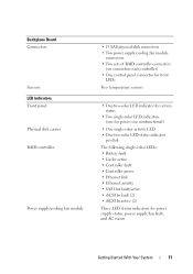
...Your System 11 Backplane Board Connectors Sensors LED Indicators Front panel Physical disk carrier RAID controller Power supply/cooling fan module • 15 SAS physical-disk connectors • Two power supply/cooling fan module connectors • Two sets of RAID controller connectors (six connectors each ...LED status indicator per disk The following single-color LEDs: • Battery fault • Cache active • Controller fault • Controller power • Ethernet link • Ethernet activity • SAS Out fault/active • iSCSI In fault (2) • iSCSI In active (2)...
...Your System 11 Backplane Board Connectors Sensors LED Indicators Front panel Physical disk carrier RAID controller Power supply/cooling fan module • 15 SAS physical-disk connectors • Two power supply/cooling fan module connectors • Two sets of RAID controller connectors (six connectors each ...LED status indicator per disk The following single-color LEDs: • Battery fault • Cache active • Controller fault • Controller power • Ethernet link • Ethernet activity • SAS Out fault/active • iSCSI In fault (2) • iSCSI In active (2)...
Getting Started Guide
Page 14
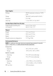
Power Supplies Wattage Voltage Frequency Amperage 488 W maximum continuous; 550 W peak 100-240 V rated (actual 90-264 V) 47-63 Hz 7.2 A at 100 V, 3.6 A at 200 V Available Physical Disk Power (Per Slot) Supported physical-disk power consumption up to 1.3 A at +12 ...V up to 1.5 A at +5 V Physical Height Width Depth Weight (maximum configuration) 13.11 cm (5.16 in) 44.63 cm (17.57 in) 48.01 cm (18.9 in) 35.37 kg (78 lb) Environmental (Enclosure) NOTE: For additional information about environmental measurements for specific system configurations, see dell...
Power Supplies Wattage Voltage Frequency Amperage 488 W maximum continuous; 550 W peak 100-240 V rated (actual 90-264 V) 47-63 Hz 7.2 A at 100 V, 3.6 A at 200 V Available Physical Disk Power (Per Slot) Supported physical-disk power consumption up to 1.3 A at +12 ...V up to 1.5 A at +5 V Physical Height Width Depth Weight (maximum configuration) 13.11 cm (5.16 in) 44.63 cm (17.57 in) 48.01 cm (18.9 in) 35.37 kg (78 lb) Environmental (Enclosure) NOTE: For additional information about environmental measurements for specific system configurations, see dell...
Hardware Owner's Manual
Page 3
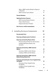
... the Enclosure Bezel 13 Front-Panel Indicators and Features 14 Back-Panel Indicators and Features 18 RAID Controller Modules 18 Cache Functions and Features 24 Power Supply and Cooling Fan Features . . . . . 24 2 Using Your RAID Enclosure 27 Physical Disks, Virtual Disks, and Disk Groups . . . . 27 Physical Disks 28 Physical Disk States 28...
... the Enclosure Bezel 13 Front-Panel Indicators and Features 14 Back-Panel Indicators and Features 18 RAID Controller Modules 18 Cache Functions and Features 24 Power Supply and Cooling Fan Features . . . . . 24 2 Using Your RAID Enclosure 27 Physical Disks, Virtual Disks, and Disk Groups . . . . 27 Physical Disks 28 Physical Disk States 28...
Hardware Owner's Manual
Page 5
... 60 Removing a RAID Controller Module 60 Installing a RAID Controller Module 61 Removing and Installing a RAID Controller Module Backup Battery Unit 62 Removing and Installing the Power Supply/Cooling Fan Module 64 Removing a Power Supply/Cooling Fan Module 64 Installing a Power Supply/Cooling Fan Module 65 Contents 5
... 60 Removing a RAID Controller Module 60 Installing a RAID Controller Module 61 Removing and Installing a RAID Controller Module Backup Battery Unit 62 Removing and Installing the Power Supply/Cooling Fan Module 64 Removing a Power Supply/Cooling Fan Module 64 Installing a Power Supply/Cooling Fan Module 65 Contents 5

Hardware Owner's Manual
Page 6
... Safety First-For You and Your Enclosure 71 Start-Up Routine 71 Troubleshooting External Connections 72 Troubleshooting a Wet Enclosure 72 Troubleshooting a Damaged Enclosure 73 Troubleshooting Power Supplies 73 Troubleshooting Enclosure Cooling Problems . . . . . 75 Troubleshooting a Fan 75 Troubleshooting SAS Physical Disks 76 Troubleshooting Enclosure Connections 77 Hard Controller Failures and Lockdown Conditions 78...
... Safety First-For You and Your Enclosure 71 Start-Up Routine 71 Troubleshooting External Connections 72 Troubleshooting a Wet Enclosure 72 Troubleshooting a Damaged Enclosure 73 Troubleshooting Power Supplies 73 Troubleshooting Enclosure Cooling Problems . . . . . 75 Troubleshooting a Fan 75 Troubleshooting SAS Physical Disks 76 Troubleshooting Enclosure Connections 77 Hard Controller Failures and Lockdown Conditions 78...
Hardware Owner's Manual
Page 9
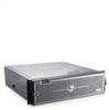
... System 9 Enclosure Features Features include: • Support for up to 16 host servers. The MD3000i storage array provides dual active/active RAID controller modules, redundant power supplies, and redundant fans. Dual-controller configurations for both single RAID controller configuration and dual RAID controller ... the RAID controller modules. Storage management can be daisy-chained with up to data storage. About Your System The Dell™ PowerVault™ MD3000i is a 3U rack-mounted external Redundant Array of Independent Disks (RAID) storage array capable of 45 disks in the...
... System 9 Enclosure Features Features include: • Support for up to 16 host servers. The MD3000i storage array provides dual active/active RAID controller modules, redundant power supplies, and redundant fans. Dual-controller configurations for both single RAID controller configuration and dual RAID controller ... the RAID controller modules. Storage management can be daisy-chained with up to data storage. About Your System The Dell™ PowerVault™ MD3000i is a 3U rack-mounted external Redundant Array of Independent Disks (RAID) storage array capable of 45 disks in the...
Hardware Owner's Manual
Page 10
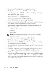
NVSRAM - Physical disk NOTE: Dell recommends stopping all I /O activity from a failed, offline, or removed RAID controller module to its alternate RAID controller module (or from a failed iSCSI connection). • Two redundant, hot-pluggable power supply/fan modules • 512 MB of mirrored ...cache on each RAID controller module • Battery backup unit in each RAID controller module that protects against cache data loss for up to 72 hours • Support for up to 45 3.5" SAS physical disks • Support for up to two PowerVault...
NVSRAM - Physical disk NOTE: Dell recommends stopping all I /O activity from a failed, offline, or removed RAID controller module to its alternate RAID controller module (or from a failed iSCSI connection). • Two redundant, hot-pluggable power supply/fan modules • 512 MB of mirrored ...cache on each RAID controller module • Battery backup unit in each RAID controller module that protects against cache data loss for up to 72 hours • Support for up to 45 3.5" SAS physical disks • Support for up to two PowerVault...

Hardware Owner's Manual
Page 13
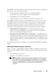
...enclosure, including: • Indicators on the enclosure bezel • Front-panel and back-panel indicators and features • Redundant power supply and cooling fan modules Indicators on the Enclosure Bezel An optional locking bezel can be installed on the front of how to ...the Front Bezel" on the Front Bezel 1 2 3 About Your System 13 Figure 1-1. LEDs on page 55. Each MD3000i RAID controller module also contains a SAS Out port connector. Refer to the PowerVault MD3000i Installation Guide for details and illustrated examples of the enclosure to an expansion enclosure.
...enclosure, including: • Indicators on the enclosure bezel • Front-panel and back-panel indicators and features • Redundant power supply and cooling fan modules Indicators on the Enclosure Bezel An optional locking bezel can be installed on the front of how to ...the Front Bezel" on the Front Bezel 1 2 3 About Your System 13 Figure 1-1. LEDs on page 55. Each MD3000i RAID controller module also contains a SAS Out port connector. Refer to the PowerVault MD3000i Installation Guide for details and illustrated examples of the enclosure to an expansion enclosure.

Hardware Owner's Manual
Page 14
...in reset state. Flashing amber: Enclosure is unused in fault state. Table 1-1. Front-Bezel Indicators Item LED Indicator 1 Split mode (green) 2 Power (green) LED Icon Condition Because this mode is in the system, this LED should always be unlit. NOTE: This LED comes on if ... on and enclosure status is being blinked by each. 14 About Your System When lit, at least one power supply is supplying power to the enclosure. 3 Enclosure status (blue/amber) Steady amber: Power is on the enclosure's front panel (optional locking bezel not shown). Flashing blue: Enclosure LED is OK....
...in reset state. Flashing amber: Enclosure is unused in fault state. Table 1-1. Front-Bezel Indicators Item LED Indicator 1 Split mode (green) 2 Power (green) LED Icon Condition Because this mode is in the system, this LED should always be unlit. NOTE: This LED comes on if ... on and enclosure status is being blinked by each. 14 About Your System When lit, at least one power supply is supplying power to the enclosure. 3 Enclosure status (blue/amber) Steady amber: Power is on the enclosure's front panel (optional locking bezel not shown). Flashing blue: Enclosure LED is OK....
Hardware Owner's Manual
Page 16
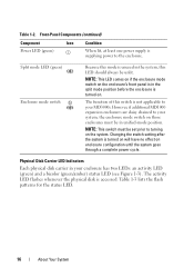
... switch on the enclosure's front panel is in your MD3000i. NOTE: This switch must be unlit. Front-Panel Components (continued) Component Icon Condition Power LED (green) When lit, at least one power supply is supplying power to turning on enclosure configuration until the system goes through a complete power cycle. Physical Disk Carrier LED Indicators Each physical disk...
... switch on the enclosure's front panel is in your MD3000i. NOTE: This switch must be unlit. Front-Panel Components (continued) Component Icon Condition Power LED (green) When lit, at least one power supply is supplying power to turning on enclosure configuration until the system goes through a complete power cycle. Physical Disk Carrier LED Indicators Each physical disk...

Hardware Owner's Manual
Page 18
...contains 512 MB of the enclosure. Figure 1-4. Back-Panel Features 1 2 3 1 RAID controller module 0 2 RAID controller module 1 3 power supply/cooling fan modules (2) RAID Controller Modules The RAID controller modules provide high-performance, advanced virtual disk configuration, and fault-tolerant disk subsystem management....Features Figure 1-4 shows the back-panel features of cache that is mirrored with dual RAID controllers and two power supply/cooling fan modules is shown. For more information, see "Power Supply and Cooling Fan Features" on one power supply/cooling fan module.
...contains 512 MB of the enclosure. Figure 1-4. Back-Panel Features 1 2 3 1 RAID controller module 0 2 RAID controller module 1 3 power supply/cooling fan modules (2) RAID Controller Modules The RAID controller modules provide high-performance, advanced virtual disk configuration, and fault-tolerant disk subsystem management....Features Figure 1-4 shows the back-panel features of cache that is mirrored with dual RAID controllers and two power supply/cooling fan modules is shown. For more information, see "Power Supply and Cooling Fan Features" on one power supply/cooling fan module.
Hardware Owner's Manual
Page 19
...provides data path and enclosure management functions for your enclosure, including: • Monitoring and controlling enclosure environment elements (temperature, fans, power supplies, and enclosure LEDs) • Controlling access to the physical disks • Communicating enclosure attributes and states to the host server Each..., in both single controller and dual controller mode, to connect the storage enclosure to hosts depending on cabling, see the PowerVault MD3000i Installation Guide. If a DHCP server is not available (time-out is 10 seconds) then the RAID controller modules uses the...
...provides data path and enclosure management functions for your enclosure, including: • Monitoring and controlling enclosure environment elements (temperature, fans, power supplies, and enclosure LEDs) • Controlling access to the physical disks • Communicating enclosure attributes and states to the host server Each..., in both single controller and dual controller mode, to connect the storage enclosure to hosts depending on cabling, see the PowerVault MD3000i Installation Guide. If a DHCP server is not available (time-out is 10 seconds) then the RAID controller modules uses the...

Hardware Owner's Manual
Page 23
...RAID Controller Module Backup Battery Unit" on the physical disks from corruption in the cache is not necessary to shut down the enclosure power supplies within specified ranges, or if the battery is reenabled. RAID Enclosure Thermal Shutdown Enclosure management provides a feature that automatically shuts down ... the battery backup unit protects against cache data loss for all data in the event of the enclosure power supplies occurs within the storage enclosure exceeds a safe threshold. It is saved. Temperature threshold values are default settings and cannot be changed.
...RAID Controller Module Backup Battery Unit" on the physical disks from corruption in the cache is not necessary to shut down the enclosure power supplies within specified ranges, or if the battery is reenabled. RAID Enclosure Thermal Shutdown Enclosure management provides a feature that automatically shuts down ... the battery backup unit protects against cache data loss for all data in the event of the enclosure power supplies occurs within the storage enclosure exceeds a safe threshold. It is saved. Temperature threshold values are default settings and cannot be changed.

Hardware Owner's Manual
Page 24
...must be written. Cache mirroring is enabled by default. The enclosure requires at a more secure than write-back cache, since a power failure is returned to ensure proper cooling. Write-through if cache mirroring is disabled or if the battery is a caching strategy whereby ... initiator. The target physical disk will receive the data at least three of data. Power Supply and Cooling Fan Features Your RAID enclosure supports two integrated, hot-pluggable power supply/cooling fan modules. Cache Functions and Features Cache Mirroring The cache mirroring function copies accepted...
...must be written. Cache mirroring is enabled by default. The enclosure requires at a more secure than write-back cache, since a power failure is returned to ensure proper cooling. Write-through if cache mirroring is disabled or if the battery is a caching strategy whereby ... initiator. The target physical disk will receive the data at least three of data. Power Supply and Cooling Fan Features Your RAID enclosure supports two integrated, hot-pluggable power supply/cooling fan modules. Cache Functions and Features Cache Mirroring The cache mirroring function copies accepted...

Hardware Owner's Manual
Page 25
... "Removing and Installing the Power Supply/Cooling Fan Module" on /off switch 3 AC power LED 6 AC power connector About Your System 25 Figure 1-7 shows the power supply/cooling fan module features and LED indicators. Table 1-5 lists the LED indicator descriptions. Power Supply and Cooling Fan Module LED Features and Indicators 1 2 3 4 6 1 DC power LED 4 cooling fans (2) 5 2 Power supply/cooling fan fault LED...
... "Removing and Installing the Power Supply/Cooling Fan Module" on /off switch 3 AC power LED 6 AC power connector About Your System 25 Figure 1-7 shows the power supply/cooling fan module features and LED indicators. Table 1-5 lists the LED indicator descriptions. Power Supply and Cooling Fan Module LED Features and Indicators 1 2 3 4 6 1 DC power LED 4 cooling fans (2) 5 2 Power supply/cooling fan fault LED...

Hardware Owner's Manual
Page 26
Off: No power or voltages not within specifications. 26 About Your System Off: No power or voltages not within specifications. Off: No fault condition is within specifications. AC power Green On: AC input voltage is present. On: DC output voltages are not within specifications or one (or both) fans are within specifications. Table 1-5. Power Supply/Cooling Fan Module LED Indicators Type DC power Color Icon Green Power Amber supply/cooling fan fault Function On: DC output voltages are in fault.
Off: No power or voltages not within specifications. 26 About Your System Off: No power or voltages not within specifications. Off: No fault condition is within specifications. AC power Green On: AC input voltage is present. On: DC output voltages are not within specifications or one (or both) fans are within specifications. Table 1-5. Power Supply/Cooling Fan Module LED Indicators Type DC power Color Icon Green Power Amber supply/cooling fan fault Function On: DC output voltages are in fault.


