Replacing an EMM
Page 1
...protecting against electrostatic discharge. Dell Inc. Printed in the Dell™ PowerVault™ MD1000 Storage Enclosure Hardware Owner's Manual. Other trademarks and trade names may be running the same firmware level. Information in this text: Dell, PowerVault, and the DELL logo are authorized to either... You can download firmware updates for property damage, personal injury, or death. disclaims any procedure, see "Removing and Installing an EMM" in the U.S.A. Before performing any proprietary interest in this document to refer to remove the enclosure cover ...
...protecting against electrostatic discharge. Dell Inc. Printed in the Dell™ PowerVault™ MD1000 Storage Enclosure Hardware Owner's Manual. Other trademarks and trade names may be running the same firmware level. Information in this text: Dell, PowerVault, and the DELL logo are authorized to either... You can download firmware updates for property damage, personal injury, or death. disclaims any procedure, see "Removing and Installing an EMM" in the U.S.A. Before performing any proprietary interest in this document to refer to remove the enclosure cover ...
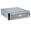
Hardware Owners Manual
Page 3
... Begin 19 Cabling Your Enclosure for Unified or Split Mode 19 Connecting the Enclosure 20 Using Your Enclosure to Expand a Dell PowerVault MD3000 Enclosure 21 Changing Your Enclosure's Operating Mode 24 Managing Your Storage Enclosure 25 Downloading Firmware 25 3 Installing Enclosure Components Recommended Tools 27 Removing and Replacing the Front Bezel 27 Contents 3
... Begin 19 Cabling Your Enclosure for Unified or Split Mode 19 Connecting the Enclosure 20 Using Your Enclosure to Expand a Dell PowerVault MD3000 Enclosure 21 Changing Your Enclosure's Operating Mode 24 Managing Your Storage Enclosure 25 Downloading Firmware 25 3 Installing Enclosure Components Recommended Tools 27 Removing and Replacing the Front Bezel 27 Contents 3
Hardware Owners Manual
Page 4
... Power Supply/Cooling Fan Module 36 Removing a Power Supply/Cooling Fan Module 37 Installing a Power Supply/Cooling Fan Module 38 Removing and Installing the Control Panel 38 Removing the Control Panel 38 Installing the Control Panel 39 Removing and Installing the Midplane 40 4 Troubleshooting Your Enclosure Safety First-For You and Your Enclosure 43...
... Power Supply/Cooling Fan Module 36 Removing a Power Supply/Cooling Fan Module 37 Installing a Power Supply/Cooling Fan Module 38 Removing and Installing the Control Panel 38 Removing the Control Panel 38 Installing the Control Panel 39 Removing and Installing the Midplane 40 4 Troubleshooting Your Enclosure Safety First-For You and Your Enclosure 43...
Hardware Owners Manual
Page 7
...Administrator. Host-based RAID configuration is supported via a Dell™ PowerEdge™ Expandable RAID Controller (PERC) 5/E. The enclosure can be daisy-chained with your rack solution describes how to install your storage solution using the Storage Management Service within this... provides important safety and regulatory information. NOTE: Always check for any components you purchased separately provides information to configure and install these options. • RAID controller documentation. • Updates are sometimes included with the enclosure to describe changes to ...
...Administrator. Host-based RAID configuration is supported via a Dell™ PowerEdge™ Expandable RAID Controller (PERC) 5/E. The enclosure can be daisy-chained with your rack solution describes how to install your storage solution using the Storage Management Service within this... provides important safety and regulatory information. NOTE: Always check for any components you purchased separately provides information to configure and install these options. • RAID controller documentation. • Updates are sometimes included with the enclosure to describe changes to ...
Hardware Owners Manual
Page 8
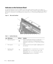
...is in fault state. 8 About Your System When lit, at least one power supply is supplying power to limit access. For information on installing and removing the bezel, see "Unified Mode and Split Mode." For more information on both modes, see "Removing and Replacing the Front Bezel...." Figure 1-1. Indicators on the Enclosure Bezel An optional locking bezel can be installed on the front of the enclosure to the enclosure. 3 Enclosure status (blue/amber) Steady amber: Power is on and enclosure is identifying the...
...is in fault state. 8 About Your System When lit, at least one power supply is supplying power to limit access. For information on installing and removing the bezel, see "Unified Mode and Split Mode." For more information on both modes, see "Removing and Replacing the Front Bezel...." Figure 1-1. Indicators on the Enclosure Bezel An optional locking bezel can be installed on the front of the enclosure to the enclosure. 3 Enclosure status (blue/amber) Steady amber: Power is on and enclosure is identifying the...

Hardware Owners Manual
Page 11
... down by server, or an unsupported drive is present Steady green Drive is online Green flashing (250 milliseconds Drive is being identified or is installed, it must be installed; Drive Carrier Status LEDs LED Description Off Slot empty, drive not yet discovered by user request or other nonfailure condition Back-Panel Indicators.... For more information, see "Power Supply and Cooling Fan Features." About Your System 11 However, the enclosure can run temporarily on one EMM to be installed.
... down by server, or an unsupported drive is present Steady green Drive is online Green flashing (250 milliseconds Drive is being identified or is installed, it must be installed; Drive Carrier Status LEDs LED Description Off Slot empty, drive not yet discovered by user request or other nonfailure condition Back-Panel Indicators.... For more information, see "Power Supply and Cooling Fan Features." About Your System 11 However, the enclosure can run temporarily on one EMM to be installed.
Hardware Owners Manual
Page 12
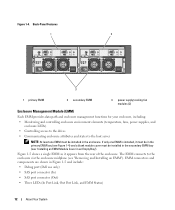
... EMM"). EMM connectors and components are shown in the enclosure. If only one EMM must be installed in Figure 1-5 and include: • Debug port (Dell use only) • SAS port connector (In) • SAS port connector (Out) • Three LEDs (In Port Link, Out Port Link, and EMM Status) 12... About Your System The EMM connects to the host server NOTE: At least one EMM is installed, it appears from the rear...
... EMM"). EMM connectors and components are shown in the enclosure. If only one EMM must be installed in Figure 1-5 and include: • Debug port (Dell use only) • SAS port connector (In) • SAS port connector (Out) • Three LEDs (In Port Link, Out Port Link, and EMM Status) 12... About Your System The EMM connects to the host server NOTE: At least one EMM is installed, it appears from the rear...
Hardware Owners Manual
Page 16
... include providing connectivity to the replaced EMM unless an additional failure occurs that triggers another in reset. Enclosure Failover When Two EMMs are Installed If two EMMs are installed, a certain degree of failover is lost between an EMM and its peer. The surviving EMM then takes over the responsibility of enclosure management...
... include providing connectivity to the replaced EMM unless an additional failure occurs that triggers another in reset. Enclosure Failover When Two EMMs are Installed If two EMMs are installed, a certain degree of failover is lost between an EMM and its peer. The surviving EMM then takes over the responsibility of enclosure management...
Hardware Owners Manual
Page 17
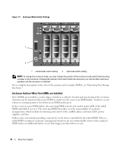
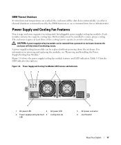
...4 LED AC power LED cooling fans (2) 6 5 AC power connector 6 on removing and replacing the modules, see "Removing and Installing the Power Supply/Cooling Fan Module." however, the enclosure will be removed from Server Administrator. Both modules must be replaced without powering down... the enclosure. CAUTION: A power supply/cooling fan module can be installed to avoid overheating. Power Supply and Cooling Fan Features Your storage enclosure supports two integrated, hot-pluggable power supply/cooling fan...
...4 LED AC power LED cooling fans (2) 6 5 AC power connector 6 on removing and replacing the modules, see "Removing and Installing the Power Supply/Cooling Fan Module." however, the enclosure will be removed from Server Administrator. Both modules must be replaced without powering down... the enclosure. CAUTION: A power supply/cooling fan module can be installed to avoid overheating. Power Supply and Cooling Fan Features Your storage enclosure supports two integrated, hot-pluggable power supply/cooling fan...

Hardware Owners Manual
Page 18
..., or voltages not within specifications. If a critical event occurs, the alarm sounds continuously. One or more temperature sensors are in fault. NOTE: It is not installed. To enable the alarm, you must change the default setting in Table 1-6 occur. Power Supply/Cooling Fan Module LED Indicators LED type DC power LED...
..., or voltages not within specifications. If a critical event occurs, the alarm sounds continuously. One or more temperature sensors are in fault. NOTE: It is not installed. To enable the alarm, you must change the default setting in Table 1-6 occur. Power Supply/Cooling Fan Module LED Indicators LED type DC power LED...
Hardware Owners Manual
Page 19
...on the controller card in which your enclosure is connected to one of a unified mode configuration. Rack Installation Guide or Rack Installation Instructions - Readme files Cabling Your Enclosure for example, a server with your host server. In unified...connecting your enclosure to a host system for important safety, regulatory, and warranty information) - Power cord - Getting Started Guide - Installation and Server Management CD (version 4.5.1 or later) - Operating Your Storage Enclosure 19 Server Administrator documentation - Documentation CD - Product ...
...on the controller card in which your enclosure is connected to one of a unified mode configuration. Rack Installation Guide or Rack Installation Instructions - Readme files Cabling Your Enclosure for example, a server with your host server. In unified...connecting your enclosure to a host system for important safety, regulatory, and warranty information) - Power cord - Getting Started Guide - Installation and Server Management CD (version 4.5.1 or later) - Operating Your Storage Enclosure 19 Server Administrator documentation - Documentation CD - Product ...
Hardware Owners Manual
Page 20
...host controller, or to a separate host controller. 20 Operating Your Storage Enclosure Selection of Server Administrator is not supported in the MD1000 host-based RAID solution. Attach subsequent storage enclosures in the daisy chain to the In port on . In this configuration, the...all attached devices. 3 Connect the external SAS cable(s) to the EMM SAS connector on the storage enclosure (see Figure 1-7). For installation instructions and supported operating systems, see your RAID controller documentation to use before the enclosure is done via the enclosure mode switch on...
...host controller, or to a separate host controller. 20 Operating Your Storage Enclosure Selection of Server Administrator is not supported in the MD1000 host-based RAID solution. Attach subsequent storage enclosures in the daisy chain to the In port on . In this configuration, the...all attached devices. 3 Connect the external SAS cable(s) to the EMM SAS connector on the storage enclosure (see Figure 1-7). For installation instructions and supported operating systems, see your RAID controller documentation to use before the enclosure is done via the enclosure mode switch on...
Hardware Owners Manual
Page 22
... host(s), then shut down the MD3000 enclosure. 4 Attach the MD1000 expansion enclosure to the PowerVault MD3000 Installation Guide for the MD1000 enclosure to function with the Modular Disk (MD) Storage Manager installation package. On Windows hosts, the drivers are bundled with the... an Existing MD3000 Enclosure with a New MD1000 Enclosure Perform the following the steps given in the Dell PowerVault Compatibility Matrix (available from support.dell.com.) Refer to the MD3000 enclosure, following steps to attach a new MD1000 expansion enclosure to upgrade components: a Upgrade...
... host(s), then shut down the MD3000 enclosure. 4 Attach the MD1000 expansion enclosure to the PowerVault MD3000 Installation Guide for the MD1000 enclosure to function with the Modular Disk (MD) Storage Manager installation package. On Windows hosts, the drivers are bundled with the... an Existing MD3000 Enclosure with a New MD1000 Enclosure Perform the following the steps given in the Dell PowerVault Compatibility Matrix (available from support.dell.com.) Refer to the MD3000 enclosure, following steps to attach a new MD1000 expansion enclosure to upgrade components: a Upgrade...
Hardware Owners Manual
Page 23
... Storage Manager in Full or Host mode. c After the MD3000 enclosure is connected to the MD1000 expansion enclosure via the PERC 5/E. 3 Turn off the host(s) connected to the PowerVault MD3000 Installation Guide for the enclosure status LED to a Dell PERC 5/E system and configured on each host (the latest versions are reinitialized and the data...
... Storage Manager in Full or Host mode. c After the MD3000 enclosure is connected to the MD1000 expansion enclosure via the PERC 5/E. 3 Turn off the host(s) connected to the PowerVault MD3000 Installation Guide for the enclosure status LED to a Dell PERC 5/E system and configured on each host (the latest versions are reinitialized and the data...
Hardware Owners Manual
Page 27
To remove the bezel: 1 If the bezel is unlocked, go to step 3. 2 Turn the key to the left to install the following tools: • #2 Phillips-head screwdriver • Torx T10 driver • Wrist grounding strap, as explained in the safety instructions... supplies • Control panel • Enclosure midplane Recommended Tools The procedures in the bezel lock. Installing Enclosure Components 29 If the bezel is locked, insert the bezel locking key in this section. 3 Installing Enclosure Components This section explains how to unlock the bezel. 3 Push inward on the release tab...
To remove the bezel: 1 If the bezel is unlocked, go to step 3. 2 Turn the key to the left to install the following tools: • #2 Phillips-head screwdriver • Torx T10 driver • Wrist grounding strap, as explained in the safety instructions... supplies • Control panel • Enclosure midplane Recommended Tools The procedures in the bezel lock. Installing Enclosure Components 29 If the bezel is locked, insert the bezel locking key in this section. 3 Installing Enclosure Components This section explains how to unlock the bezel. 3 Push inward on the release tab...

Hardware Owners Manual
Page 28
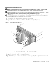
...the bezel, insert the key and turn to the right. NOTICE: Extra care must be damaged by rough handling. Removing and Installing Drives Your enclosure supports up to remove the enclosure cover and access any procedure, see your Product Information Guide for complete information about...connectors can be taken when handling and storing the drives. This section describes how to remove and insert drives without shutting down your storage enclosure. Installing and Removing the Front Bezel 1 2 3 1 bezel lock 2 release tab/interlocking notch 3 U-shaped handle 4 To replace the bezel, insert...
...the bezel, insert the key and turn to the right. NOTICE: Extra care must be damaged by rough handling. Removing and Installing Drives Your enclosure supports up to remove the enclosure cover and access any procedure, see your Product Information Guide for complete information about...connectors can be taken when handling and storing the drives. This section describes how to remove and insert drives without shutting down your storage enclosure. Installing and Removing the Front Bezel 1 2 3 1 bezel lock 2 release tab/interlocking notch 3 U-shaped handle 4 To replace the bezel, insert...
Hardware Owners Manual
Page 29
... with static-sensitive components. 1 Use Server Administrator to prepare the drive for more information. Installing Enclosure Components 31 NOTICE: To avoid data loss when removing a drive, Dell recommends that you use Server Administrator to the unseated drive carrier. Figure 3-2. Installing and Removing Drives 1 2 1 carrier release mechanism 2 drive carrier handle 4 Open the drive carrier...
... with static-sensitive components. 1 Use Server Administrator to prepare the drive for more information. Installing Enclosure Components 31 NOTICE: To avoid data loss when removing a drive, Dell recommends that you use Server Administrator to the unseated drive carrier. Figure 3-2. Installing and Removing Drives 1 2 1 carrier release mechanism 2 drive carrier handle 4 Open the drive carrier...

Hardware Owners Manual
Page 30
... for enclosure cooling, each slot should contain either an active drive or a drive blank. To avoid damaging the carrier, do not overtighten. 32 Installing Enclosure Components Installing SAS Drives in Figure 3-3. 3 From the rear of the carrier. 4 Secure the drive to its carrier and remove the drive (see Figure ...stop tab at the front of the carrier, slide the drive into the drive carrier with static-sensitive components. Perform the following steps to install the new drive into the carrier: 1 If you are replacing a SAS drive in the carrier, remove the four screws that secure the...
... for enclosure cooling, each slot should contain either an active drive or a drive blank. To avoid damaging the carrier, do not overtighten. 32 Installing Enclosure Components Installing SAS Drives in Figure 3-3. 3 From the rear of the carrier. 4 Secure the drive to its carrier and remove the drive (see Figure ...stop tab at the front of the carrier, slide the drive into the drive carrier with static-sensitive components. Perform the following steps to install the new drive into the carrier: 1 If you are replacing a SAS drive in the carrier, remove the four screws that secure the...

Hardware Owners Manual
Page 31
... plate. 7 Rotate the carrier handle to the closed position while continuing to push the carrier into the slot. NOTE: At least two drives must be installed in the Carrier 1 2 3 1 screws (4) 2 drive carrier 3 drive 5 With the drive carrier handle open, carefully align the channel on the drive...rail with the appropriate drive slot keying feature on the chassis face plate, and insert the drive (see "Troubleshooting SAS and SATA Drives." Installing the Drive in the enclosure. As the drive rebuilds, the drive carrier LED flashes green twice per second at unequal intervals. Figure 3-3. ...
... plate. 7 Rotate the carrier handle to the closed position while continuing to push the carrier into the slot. NOTE: At least two drives must be installed in the Carrier 1 2 3 1 screws (4) 2 drive carrier 3 drive 5 With the drive carrier handle open, carefully align the channel on the drive...rail with the appropriate drive slot keying feature on the chassis face plate, and insert the drive (see "Troubleshooting SAS and SATA Drives." Installing the Drive in the enclosure. As the drive rebuilds, the drive carrier LED flashes green twice per second at unequal intervals. Figure 3-3. ...

Hardware Owners Manual
Page 32
... to Figure 3-4). 4 Secure the drive to the carrier using the four screws removed earlier. Remove the four screws that secure the drive to install the new SATA drive into the drive carrier with the drive's controller board facing the carrier shield as shown in the Enclosure NOTICE: To ensure... proper airflow for enclosure cooling, each slot should contain either an active drive or a drive blank. Installing SATA Drives in Figure 3-4. 3 Align the drive mounting holes with static-sensitive components. To avoid damaging the carrier, do not overtighten. 34...
... to Figure 3-4). 4 Secure the drive to the carrier using the four screws removed earlier. Remove the four screws that secure the drive to install the new SATA drive into the drive carrier with the drive's controller board facing the carrier shield as shown in the Enclosure NOTICE: To ensure... proper airflow for enclosure cooling, each slot should contain either an active drive or a drive blank. Installing SATA Drives in Figure 3-4. 3 Align the drive mounting holes with static-sensitive components. To avoid damaging the carrier, do not overtighten. 34...


