Information Update - Processor Installation
Page 3
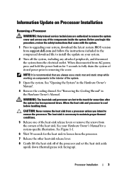
.... 1 Prior to upgrading your system. 2 Turn off of the processor and set the heat sink aside upside down . Before you begin this procedure, review the safety instructions that you intend to remove the system cover and access any attached peripherals, and disconnect the system from support....dell.com and follow the instructions included in the interior of the system. 3 Open the system. When disconnected from AC power, press and hold ...
.... 1 Prior to upgrading your system. 2 Turn off of the processor and set the heat sink aside upside down . Before you begin this procedure, review the safety instructions that you intend to remove the system cover and access any attached peripherals, and disconnect the system from support....dell.com and follow the instructions included in the interior of the system. 3 Open the system. When disconnected from AC power, press and hold ...
Information Update - Processor Installation
Page 6
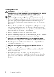
... the vacant processor socket. See Figure 1-4. See Figure 1-4. 7 Install the processor in the processor with your hand beneath the processor when you begin this procedure, review the safety instructions that came with each pin 1 aligned and level. Before you are adding a second processor for the first time, remove the heatsink blank...
... the vacant processor socket. See Figure 1-4. See Figure 1-4. 7 Install the processor in the processor with your hand beneath the processor when you begin this procedure, review the safety instructions that came with each pin 1 aligned and level. Before you are adding a second processor for the first time, remove the heatsink blank...

Getting Started Guide
Page 5
Unpacking the System Unpack your system. Getting Started With Your System 3 Installing the Rails and System in a Rack Assemble the rails and install the system in the rack following procedure, review the safety instructions that came with your system and identify each item. Installation and Configuration WARNING: Before performing the following the safety instructions and the rack installation instructions provided with the system.
Unpacking the System Unpack your system. Getting Started With Your System 3 Installing the Rails and System in a Rack Assemble the rails and install the system in the rack following procedure, review the safety instructions that came with your system and identify each item. Installation and Configuration WARNING: Before performing the following the safety instructions and the rack installation instructions provided with the system.

Hardware Owner's Manual
Page 29
... parity error on a component that Remove and reseat the resides in PCI "Troubleshooting configuration space at bus ##, device ##, function ##. Review & clear SEL. on Slot #. problem persists, the riser card or system board is faulty. LCD Status Messages (continued) Code ...PCI parity error on a component that the problem persists, see "Troubleshooting Expansion Cards." Remove and reseat the PCIe expansion cards. Review & clear SEL. Review & clear SEL. See "Getting Help." If on Slot #. See "Expansion- If the problem persists, see "Getting Help...
... parity error on a component that Remove and reseat the resides in PCI "Troubleshooting configuration space at bus ##, device ##, function ##. Review & clear SEL. on Slot #. problem persists, the riser card or system board is faulty. LCD Status Messages (continued) Code ...PCI parity error on a component that the problem persists, see "Troubleshooting Expansion Cards." Remove and reseat the PCIe expansion cards. Review & clear SEL. Review & clear SEL. See "Getting Help." If on Slot #. See "Expansion- If the problem persists, see "Getting Help...

Hardware Owner's Manual
Page 30
... SEL. Check the SEL for details of the error message and then clear the SEL. Review & clear SEL. If the problem persists, see "Getting Help." Check the SEL for 10 seconds and restart the system. Remove AC power to the system ... an error in bus ##, device ##, function##. E1716 Chipset IERR Bus ## Dev ## Function ##. Remove AC power to the system for 10 seconds and restart the system. Review & clear SEL. See "Troubleshooting the Processors." Remove AC power to determine its origin. Table 1-1. E1717 CPU ## internal error...
... SEL. Check the SEL for details of the error message and then clear the SEL. Review & clear SEL. If the problem persists, see "Getting Help." Check the SEL for 10 seconds and restart the system. Remove AC power to the system ... an error in bus ##, device ##, function##. E1716 Chipset IERR Bus ## Dev ## Function ##. Remove AC power to the system for 10 seconds and restart the system. Review & clear SEL. See "Troubleshooting the Processors." Remove AC power to determine its origin. Table 1-1. E1717 CPU ## internal error...

Hardware Owner's Manual
Page 31
... PCIe fatal error on Bus ## Device ## Function ## The system BIOS has reported a PCIe fatal error on a component that Card Risers." Review & clear SEL. reported a PCIe fatal error card riser. E1812 Hard drive ## The specified hard drive Information only. See "ExpansionCard Risers." ...Getting Help." Some configuration invalid configurations mismatch. See "Replacing an the system from the Check drive. SAS cable A is missing. on . Review has experienced a fault. & clear SEL. removed. powering on a component that resides in the specified slot. One or all of the PCIe...
... PCIe fatal error on Bus ## Device ## Function ## The system BIOS has reported a PCIe fatal error on a component that Card Risers." Review & clear SEL. reported a PCIe fatal error card riser. E1812 Hard drive ## The specified hard drive Information only. See "ExpansionCard Risers." ...Getting Help." Some configuration invalid configurations mismatch. See "Replacing an the system from the Check drive. SAS cable A is missing. on . Review has experienced a fault. & clear SEL. removed. powering on a component that resides in the specified slot. One or all of the PCIe...

Hardware Owner's Manual
Page 34
... SMI System management initializatio interrupt (SMI) n failure. Remove AC power to the system for 10 seconds and restart the system. BIOS shutdown test failure. failure. Review User Guide. If the problem persists, see "Getting Help." E201D Shutdown test failure. Check screen message. Incorrect memory configuration. E2022 General failure during POST. Table...
... SMI System management initializatio interrupt (SMI) n failure. Remove AC power to the system for 10 seconds and restart the system. BIOS shutdown test failure. failure. Review User Guide. If the problem persists, see "Getting Help." E201D Shutdown test failure. Check screen message. Incorrect memory configuration. E2022 General failure during POST. Table...

Hardware Owner's Manual
Page 35
... of events and is rebooted. I1910 Intrusion detected. System cover has been removed. See "Troubleshooting System Memory." "## & ##" represents the DIMM pair implicated by the BIOS. Review & clear log. The SEL is full of the error messages, then clear the SEL. Reseat DIMM. The system BIOS has Remove AC power to log...
... of events and is rebooted. I1910 Intrusion detected. System cover has been removed. See "Troubleshooting System Memory." "## & ##" represents the DIMM pair implicated by the BIOS. Review & clear log. The SEL is full of the error messages, then clear the SEL. Reseat DIMM. The system BIOS has Remove AC power to log...

Hardware Owner's Manual
Page 42
... that the mouse or keyboard is enabled in BIOS. Reseat the mouse or keyboard cable. See "Troubleshooting a USB Device." Run the System Setup program and review the current settings. The OS NIC=DISABLED, Management Shared NIC Management interface is indicated, see "Troubleshooting a NIC." Error 8602 Auxiliary Device Failure. Ensure that mouse...
... that the mouse or keyboard is enabled in BIOS. Reseat the mouse or keyboard cable. See "Troubleshooting a USB Device." Run the System Setup program and review the current settings. The OS NIC=DISABLED, Management Shared NIC Management interface is indicated, see "Troubleshooting a NIC." Error 8602 Auxiliary Device Failure. Ensure that mouse...

